2004 DAEWOO LACETTI Lamp
[x] Cancel search: LampPage 2329 of 2643

9E – 30IINSTRUMENTATION/DRIVER INFORMATION
DAEWOO V–121 BL4
GENERAL DESCRIPTION
AND SYSTEM OPERATION
CIGAR LIGHTER
The cigar lighter is located in the front portion of the floor
console. To use the lighter, push it in completely. When the
lighter is hot, it will release itself from contact with the heat-
ing element. The lighter and the heating element can be
damaged if the lighter is not allowed to release itself fully
from the heating element.
ASHTRAY
The ashtray is located below the audio system. To access
the ashtray, pull it out from the center console. The ashtray
lamp will go on when the parking lamps or the headlamps
are turned on.
INSTRUMENT PANEL VENTS
The center and the side vents in the instrument panel can
be adjusted up and down and from side to side. The side
vents can also be aimed toward the side windows in order
to defog them.
GLOVE BOX
The glove box can be opened by pulling up on the latch
handle. The glove box must be removed in order to gain
access to the passenger’s side airbag module.
DIGTAL CLOCK
The digital clock is located in the instrument panel, above
the audio system. The clock is capable of a 12–hour or a
24–hour display.
INSTRUMENT CLUSTER
The instrument cluster is located above the steering col-
umn and in the instrument cluster trim panel. The instru-
ment cluster contains the instruments that provide the
driver with vehicle performance information. The instru-
ment cluster contains a speedometer, an odometer, a trip
odometer, a temperature gauge, a fuel gauge, and several
indicator lamps. For replacement of the indicator lamp
bulbs contained in the instrument cluster, refer to ”Instru-
ment Cluster Indicator Lamps Specifications” and”Instru-
ment Cluster Indicator Lamps” in this section.
SPEEDOMETER/ODOMETER/TRIP
ODOMETER
The speedometer measures the speed of the vehicle in
km/h (mph in some countries). It consists of an instrument
cluster gauge connected to the vehicle speed sensor
(VSS) on the transaxle output shaft.The odometer measures in kilometers (miles in some
countries) the total distance the vehicle has traveled since
it was manufactured. It consists of an instrument cluster
gauge connected to the VSS on the transaxle output shaft.
The trip odometer measures the distance the vehicle has
traveled since the odometer was last reset. It consists of
an instrument cluster gauge connected to the VSS on the
transaxle output shaft. The trip odometer can be reset to
zero at any time so that the driver can record the distance
traveled from any starting point.
FUEL GAUGE
The fuel gauge consists of an instrument cluster gauge
connected to a sending unit in the fuel tank.
The fuel gauge indicates the quantity of fuel in the tank
only when the ignition switch is turned to ON or ACC.
When the ignition is turned to LOCK or START, the pointer
may come to rest at any position.
TEMPERATURE GAUGE
The temperature gauge consists of an instrument cluster
gauge connected to a temperature sensor that is in con-
tact with the circulating engine coolant.
The temperature gauge indicates the temperature of the
coolant. Prolonged driving or idling in very hot weather
may cause the pointer to move beyond the center of the
gauge. The engine is overheating if the pointer moves into
the red zone at the upper limit of the gauge.
INSTRUMENT CLUSTER INDICATOR
LAMPS
The instrument cluster contains indicator lamps that indi-
cate the functioning of certain systems or the existence of
potential problems with the operation of the vehicle. The
indicator lamps are replaceable. For replacement of the in-
dicator lamps contained in the instrument cluster, refer to
”Instrument Cluster Indicator Lamps Specifications”
and”Instrument Cluster Indicator Lamps” in this section.
CHIME MODULE
The chime module is located above the instrument panel
fuse block and will sound in order to bring attention to one
or more of the following conditions:
S The lamps are on, the door is ajar, and the ignition
switch is not in ACC, ON, or START.
S The seat belt is unbuckled when the ignition switch
is in ON or START.
S The door is open when the ignition switch is in ON
or START.
S The key is left in the ignition switch when the igni-
tion is in LOCK and the door is open.
Page 2413 of 2643

9O – 2IBUMPERS AND FASCIAS
DAEWOO V–121 BL4
MAINTENANCE AND REPAIR
ON–VEHICLE SERVICE
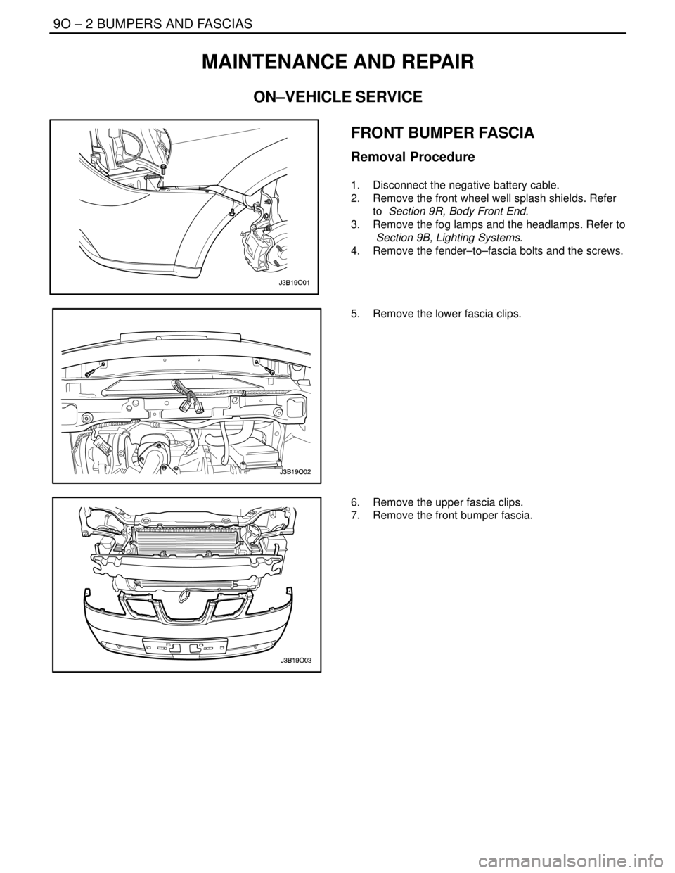
FRONT BUMPER FASCIA
Removal Procedure
1. Disconnect the negative battery cable.
2. Remove the front wheel well splash shields. Refer
to Section 9R, Body Front End.
3. Remove the fog lamps and the headlamps. Refer to
Section 9B, Lighting Systems.
4. Remove the fender–to–fascia bolts and the screws.
5. Remove the lower fascia clips.
6. Remove the upper fascia clips.
7. Remove the front bumper fascia.
Page 2414 of 2643

BUMPERS AND FASCIAS 9O – 3
DAEWOO V–121 BL4
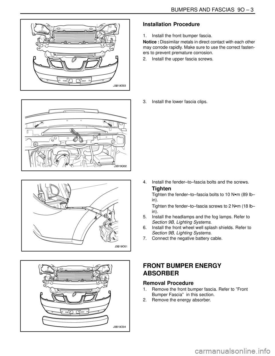
Installation Procedure
1. Install the front bumper fascia.
Notice : Dissimilar metals in direct contact with each other
may corrode rapidly. Make sure to use the correct fasten-
ers to prevent premature corrosion.
2. Install the upper fascia screws.
3. Install the lower fascia clips.
4. Install the fender–to–fascia bolts and the screws.
Tighten
Tighten the fender–to–fascia bolts to 10 NSm (89 lb–
in).
Tighten the fender–to–fascia screws to 2 NSm (18 lb–
in).
5. Install the headlamps and the fog lamps. Refer to
Section 9B, Lighting Systems.
6. Install the front wheel well splash shields. Refer to
Section 9B, Lighting Systems.
7. Connect the negative battery cable.
FRONT BUMPER ENERGY
ABSORBER
Removal Procedure
1. Remove the front bumper fascia. Refer to ”Front
Bumper Fascia” in this section.
2. Remove the energy absorber.
Page 2453 of 2643

9Q – 4IROOF
DAEWOO V–121 BL4
DIAGNOSIS
POWER SUNROOF
Power Sunroof Does Not Work
StepActionValue(s)YesNo
1Check fuse F8.
Is either fuse blown?–Go to Step 2Go to Step 3
21. Check for a short circuit and repair it, if neces-
sary.
2. Replace the blown fuse.
Is the repair complete?–System OK–
31. Turn the ignition on.
2. Check the voltages at fuse F8.
Are both voltages equal to the specified value?11 – 14 vGo to Step 5Go to Step 4
4Repair the power supply to the fuse which did not in-
dicate battery voltage with the ignition on.
Is the repair complete?–System OK–
51. Disconnect the interior courtesy lamp/power
sunroof control switch connector.
2. Turn the ignition on.
3. Check the voltage at terminal 5 of the interior
courtesy lamp/power sunroof control switch
connector.
Is the voltage equal to the specified value?11–14 vGo to Step 7Go to Step 6
6Repair the open circuit between fuse F8 and the inte-
rior courtesy lamp/power sunroof control switch con-
nector.
Is the repair complete?–System OK–
71. Reconnect the interior courtesy lamp/power
sunroof control switch connector.
2. With the sunroof switch in the OPEN position,
check the voltage at terminal 4 of the interior
courtesy lamp/power sunroof control switch
connector.
3. With the sunroof switch in the CLOSE position,
check the voltage at terminal 6 of the interior
courtesy lamp/power sunroof control switch
connector.
Do both voltages equal the specified value?11 – 14 vGo to Step 9Go to Step 8
8Replace the interior courtesy lamp/power sunroof
control switch.
Is the repair complete?–System OK–
91. Disconnect the sunroof module connector.
2. With the sunroof switch in the OPEN position,
check the voltage at terminal 1 of the sunroof
module connector.
3. With the sunroof switch in the CLOSE position,
check the voltage at terminal 6 of the sunroof
module connector.
Are the voltages equal to the specified value?11–14 vGo to Step 11Go to Step 10
Page 2454 of 2643

ROOF 9Q – 5
DAEWOO V–121 BL4
StepNo Yes Value(s) Action
10Repair the open circuit between the interior courtesy
lamp/power sunroof control switch and the sunroof
module connector.
Is the repair complete?–System OK–
111. Reconnect the sunroof module.
2. Remove the sunroof motor, but leave the con-
nectors attached.
3. Turn the ignition on.
4. Use the sunroof switch to attempt to operate
the motor in both directions.
Does the motor operate?–Go to Step 12Go to Step 13
12Repair the jammed sunroof mechanism.
Is the repair complete?–System OK–
131. Disconnect both of the one–wire connectors at
the sunroof motor.
2. Connect a voltmeter between the one–wire
connectors, on the module side of the connec-
tors.
3. Turn the ignition on.
4. Turn the sunroof switch to the OPEN position
and observe the voltmeter reading.
5. Turn the sunroof switch to the CLOSE position
and observe the voltmeter reading.
Does the voltmeter indicate the specified voltage
when the switch is in either the OPEN or the CLOSE
position (one of the switch positions should show re-
verse polarity)?11–14vGo to Step 15Go to Step 14
14Replace the sunroof module.
Is the repair complete?–System OK–
15Replace the sunroof motor.
Does the sunroof operate with the new motor?–System OKGo to Step 14
Page 2460 of 2643

ROOF 9Q – 11
DAEWOO V–121 BL4
POWER SUNROOF CONTROL
SWITCH
Removal Procedure
1. Disconnect the negative battery cable.
2. Pry off the interior courtesy lamp lens.
3. Remove the screws and the switch.
4. Disconnect the electrical connector.
Installation Procedure
1. Connect the electrical connector.
Notice : Dissimilar metals in direct contact with each other
may corrode rapidly. Make sure to use the correct fasten-
ers to prevent premature corrosion.
2. Install the sunroof control switch with the screws.
Tighten
Tighten the power sunroof control switch screws to 2
NSm (18 lb–in).
3. Install the interior courtesy lamp lens.
4. Connect the negative battery cable.
Page 2461 of 2643

9Q – 12IROOF
DAEWOO V–121 BL4
GENERAL DESCRIPTION
AND SYSTEM OPERATION
ROOF
The roof is a one–piece painted metal unit which incorpo-
rates a single solid headliner. There are two moldings, one
per side on the vehicle’s roof, which enclose and hide the
roof rail seams. The roof moldings are serviceable as indi-
vidual units.
The one–piece formed headliner consists of a molded
substrate covered with a foam–backed cloth facing. The
one–piece construction requires that the headliner be ser-
viced as a complete assembly.
POWER SUNROOF/SUNROOF
CONTROL SWITCH
The sunroof has the following characteristics:
S Intended to provide light and air through the roof
the vehicle.
S Built into the roof.
S Made of glass.
S Equipped with a sunshade that opens and closes
manually.
S Powered by an electric motor.
S Controlled by a toggle switch built into the interior
courtesy lamp assembly.
The sunroof control switch is a toggle button located on the
right side of the interior courtesy lamp assembly.
To operate the sunroof, the ignition must be ON.Tilting the Sunroof, Open and Closed
To tilt open the rear end of the sunroof, press and hold the
forward portion of the toggle button until the sunroof tilts
open.
To close the sunroof from a tilted–open position, press and
hold the rear portion of the toggle button until the sunroof
tilts closed.
Sliding the Sunroof, Open and Closed
To slide open the sunroof, press the rear portion of the
toggle button until the sunroof slides. If the sun shade is
closed, the sunroof will pull the sunshade open when the
sunroof slides open.
To close the sunroof from a slid–open position, press the
forward portion of the toggle button until the sunroof slides
closed.
SUN VISORS WITH VANITY MIRROR
The sun visors swing down in order to block out glare.
They also swing to the side when they are released from
the support. To replace the vanity mirror lamp, refer to
Section 9B, Lighting Systems.
PASSENGER ASSIST HANDLES
There is a passenger assist handle for each rear outboard
seat and for the front passenger seat. Passengers can use
these handles to assist in keeping their balance over rough
roads or during sharp turns.
COAT HOOKS
The coat hooks are located on the left and the right rear
passenger assist handles.
Page 2468 of 2643

BODY FRONT END 9R – 7
DAEWOO V–121 BL4
Installation Procedure
1. Install the screws and the front wheel well splash
shield.
Tighten
Tighten the front wheel well splash shield screws to
2 NSm (18 lb–in).
2. Install the front mud guard. Refer to Section 9M,
Exterior Trim.
3. Install the front wheel. Refer to Section 2E, Tires
and Wheels.
4. Lower the vehicle.
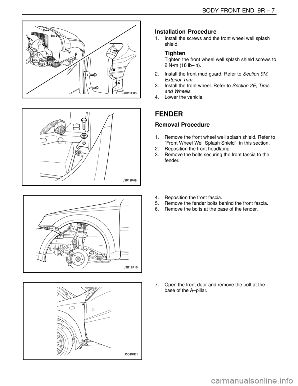
FENDER
Removal Procedure
1. Remove the front wheel well splash shield. Refer to
”Front Wheel Well Splash Shield” in this section.
2. Reposition the front headlamp.
3. Remove the bolts securing the front fascia to the
fender.
4. Reposition the front fascia.
5. Remove the fender bolts behind the front fascia.
6. Remove the bolts at the base of the fender.
7. Open the front door and remove the bolt at the
base of the A–pillar.