Page 1705 of 2643
AISIN AUTOMATIC TRANSAXLE 5A2 – 115
DAEWOO V–121 BL4
5. Install the rear mounting bracket bolts and the
bracket.
Tighten
Tighten the rear mounting bracket bolts to 60 NSm (44
Ib–ft).
6. Install the damping block connection nut and bolt.
Tighten
Tighten the damping block connection nut and bolt to
80 NSm (59 Ib–ft).
7. Install the torque converter bolts.
Tighten
Tighten the torque converter bolts to 45 NSm (33 Ib–
ft).
8. Install the service hall cover.
9. Connect the transaxle electrical connector.
10. Connect the TR switch electrical connector.
11. Connect the OSS sensor electrical connector.
12. Connect the ISS sensor electrical connector.
13. Remove engine support fixture DW110–060.
14. Connect the shift control cable into the transaxle.
Refer to ”Shift Control Cable” in this section.
Page 1708 of 2643
5A2 – 118IAISIN AUTOMATIC TRANSAXLE
DAEWOO V–121 BL4
8. Remove the screw plug from the transaxle case.
9. Remove the O–ring from the screw plug.
10. Remove the bolt and the input shaft speed (ISS)
sensor.
11. Remove the breather plug.
12. Remove the O–ring from the breather plug.
13. Remove the bolt and the output shaft speed (OSS)
sensor.
14. Remove the 18 bolts.
15. Remove the oil pan and gasket.
16. Remove the drain plug from the oil pan.
Page 1709 of 2643
AISIN AUTOMATIC TRANSAXLE 5A2 – 119
DAEWOO V–121 BL4
17. Remove the three bolts and oil strainer.
18. Remove the gasket from the oil strainer.
19. Remove the bolt and transmission fluid temperature
sensor with the clamp.
20. Disconnect the 5 solenoid connectors.
a. Lock–up control solenoid
b. Pressure control solenoid.
c. No.2 shift solenoid.
d. No.1 shift solenoid.
e. Timing solenoid
21. Support the valve body assembly and remove the
14 bolts.
Page 1752 of 2643
5A2 – 162IAISIN AUTOMATIC TRANSAXLE
DAEWOO V–121 BL4
114. Connect the manual valve control rod to the
manual valve lever as shown in the illustration.
115. Install the valve body assembly to the trans-
axle case.
Tighten
Tighten the bolts to 11 NSm (97 lb–in).
Notice : When installing the valve body to the transaxle
case, do not let each of accumulator pistons B1,C1,and
C2 incline. When installing the valve body to the transaxle
case, do not hold the solenoids.
116. Connect the transaxle wire connector and har-
ness to the valve body assembly.
117. Connect the 5 connectors.
a. Lock–up control solenoid
b. Pressure control solenoid.
c. No.2 shift solenoid.
d. No.1 shift solenoid.
e. Timing solenoid
118. Install the TFT sensor with clamp.
Notice : Make sure that the transaxle wire does not come
out from the oil pan installation surface.
119. Install a new gasket to the oil strainer.
Page 1753 of 2643
AISIN AUTOMATIC TRANSAXLE 5A2 – 163
DAEWOO V–121 BL4
120. Install the oil strainer to the valve body with the
3 bolts.
Tighten
Tighten the bolts to 9.8 NSm (87 lb–in).
121. Install the 2 magnets in the oil pan.
122. Install a new gasket to the oil pan and install
them to the transaxle case with the 18 bolts.
Tighten
Tighten the bolts to 7 NSm (62 lb–in).
123. Install the output shaft speed (OSS) sensor.
Tighten
Tighten the bolt to 7.4 NSm (65 lb–in).
Page 1754 of 2643
5A2 – 164IAISIN AUTOMATIC TRANSAXLE
DAEWOO V–121 BL4
124. Install the No.1 breather plug.
125. Install the input shaft speed (ISS) sensor with
the bolt.
Tighten
Tighten the bolts to 5.4 NSm (48 lb–in).
126. Coat a new O–ring with ATF, install it to the
screw plug.
127. Install the screw plug to the transaxle case.
Tighten
Tighten the bolts to 7.4 NSm (65 lb–in).
128. Coat new 2 O–rings with ATF, install them to
the unions.
129. Install the 2 unions to the transaxle case.
Tighten
Tighten the unions to 25 NSm (18 lb–ft).
130. Install the TR switch onto the manual valve
lever shaft and temporarily install the 2 adjusting
bolts.
131. Install a new lock washer and nuts.
Tighten
Tighten the nuts to 12 NSm (106 lb–in).
Page 1808 of 2643

5A2 – 218IAISIN AUTOMATIC TRANSAXLE
DAEWOO V–121 BL4
GENERAL DESCRIPTION
AND SYSTEM OPERATION
TRANSAXLE DESCRIPTION
The new automatic transmission is an electronically con-
trolled 4–speed automatic transmission with Lock–up
mechanism.
The transmission is mainly composed of the torque con-
verter with lock up clutch, newly developed 4–speed plan-
etary gear unit, the hydraulic control system and the elec-
tric control system.
ELECTRONICAL COMPONENTS
Transmission Control Module (TCM)
The TCM primarily controls shift points and lockup en-
gagement. It is located on the driver side under the instru-
ment panel.
The transmission is controlled by an electronic shift sys-
tem. The Transmission Control Module (TCM) processes
input signals. From the information received, the TCM
controls the transmission hydraulic system.
The electronic shift system consists of the following :
S Transmission control module (TCM)
S Shift solenoids (SS1 and SS2)
S Pressure control solenoid (PCS)
S Lockup solenoid
S Input shaft speed (ISS) sensor
S Output shaft speed (OSS) sensor
S Transmission Fluid Temperature (TFT) sensor
S Transmission Range (TR) Switch
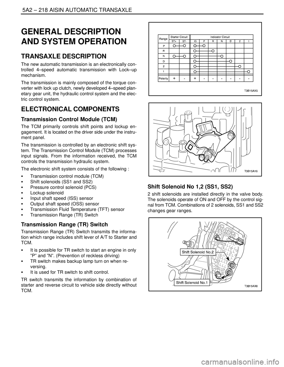
Transmission Range (TR) Switch
Transmission Range (TR) Switch transmits the informa-
tion which range includes shift lever of A/T to Starter and
TCM.
S It is possible for TR switch to start an engine in only
”P” and ”N”. (Prevention of reckless driving)
S TR switch makes backup lamp turn on when re-
versing.
S It is used for TR switch to shift control.
TR switch transmits the information by combination of
starter and reverse circuit to vehicle side directly without
TCM.
Shift Solenoid No 1,2 (SS1, SS2)
2 shift solenoids are installed directly in the valve body.
The solenoids operate of ON and OFF by the control sig-
nal from TCM. Combinations of 2 solenoids, SS1 and SS2
changes gear ranges.
Page 1809 of 2643

AISIN AUTOMATIC TRANSAXLE 5A2 – 219
DAEWOO V–121 BL4
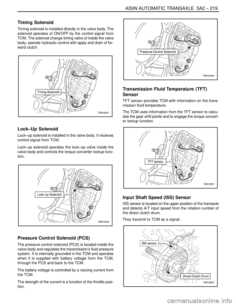
Timing Solenoid
Timing solenoid is installed directly in the valve body. The
solenoid operates of ON/OFF by the control signal from
TCM. The solenoid change timing valve of inside the valve
body, operate hydraulic control with apply and drain of for-
ward clutch.
Lock–Up Solenoid
Lock–up solenoid is installed in the valve body. It recieves
control signal from TCM.
Lock–up solenoid operates the lock–up valve inside the
valve body and controls the torque converter lockup func-
tion.
Pressure Control Solenoid (PCS)
The pressure control solenoid (PCS) is located inside the
valve body and regulates the transmission’s fluid pressure
system. It is internally grounded in the TCM and operates
when it is supplied with battery voltage from the TCM,
through the PCS and back to the TCM.
The battery voltage is controlled by a varying current from
the TCM.
The strength of the current is a function of the throttle posi-
tion.
Transmission Fluid Temperature (TFT)
Sensor
TFT sensor provides TCM with information on the trans-
mission fluid temperature.
The TCM uses information from the TFT sensor to calcu-
late the gear shift points and to engage the torque convert-
er lockup function.
Input Shaft Speed (ISS) Sensor
ISS sensor is located on the upper position of the transaxle
and detects A/T input speed from the rotation number of
the direct clutch drum.
They transmit to TCM as a signal.