Page 2076 of 2643
AUTOMATIC TEMPERATURE CONTROL HEATING, VENTILATION, AND AIR CONDITIONING SYSTEM 7D – 21
DAEWOO V–121 BL4
StepNo Yes Value(s) Action
71. Pull the ATC controller from the instrument
panel, leaving the wiring harness connected.
2. Measure the voltage between terminals A13
and B8 by backprobing the connectors.
Is the voltage equal to the value specified?< 4 vGo to Step 8Go to Step 9
8Replace the ATC Controller.
Is the repair complete?–System OK–
91. Trace the wiring for the ambient air sensor from
the ATC controller, through connectors C209,
C208, C202 and C303 to the ambient air sen-
sor connector on the front bumper harness.
2. Repair any open or high resistance condition in
the wiring or a connector terminal.
Is the repair complete?–System OK–
Page 2077 of 2643

7D – 22IAUTOMATIC TEMPERATURE CONTROL HEATING, VENTILATION, AND AIR CONDITIONING SYSTEM
DAEWOO V–121 BL4
CODE 3 – WATER SENSOR ERROR
This code will set if the output of the coolant sensor indicates a probable short circuit or an open in the sensor or the associ-
ated wiring harness, or a malfunction of the ATC controller.
Code 3 – Water Sensor Error
StepActionValue(s)YesNo
11. Disconnect the coolant temperature sensor
connector from the ATC harness.
2. Examine the wiring from the sensor to the con-
nector and examine the connector for any
signs of damage.
3. Measure the resistance between the coolant
temperature sensor connector terminals.
Is there any sign of damage in the wiring or the con-
nector, or is the resistance outside the specified val-
ue at 20 to 25°C (68 to 77°F)?2600–2100 ΩGo to Step 2Go to Step 3
2Repair the damaged wiring or the connector, or re-
place the coolant temperature sensor as required.
Is the repair complete?–System OK–
31. Turn the ignition to ON.
2. Measure the voltage between the two coolant
temperature sensor connector terminals on the
ATC harness.
Is the voltage equal to the specified value?< 4 vGo to Step 7Go to Step 4
4Check the terminals on the coolant temperature
sensor connector.
Is any problem found with the connector?–Go to Step 5Go to Step 6
5Repair the connector terminals or replace the cool-
ant temperature sensor or ATC controller as re-
quired.
Is the repair complete?–System OK–
Page 2078 of 2643
AUTOMATIC TEMPERATURE CONTROL HEATING, VENTILATION, AND AIR CONDITIONING SYSTEM 7D – 23
DAEWOO V–121 BL4
StepNo Yes Value(s) Action
61. Reconnect the coolant temperature sensor to
the ATC harness.
2. Turn the ignition switch to ON.
3. Observe the temperature display area.
Does this display indicate the continuing presence of
a code 3 condition?–Go to Step 9System OK
71. Pull the ATC controller from the instrument
panel, leaving the wiring harness connected.
2. Measure the voltage between terminals A13
and B9 by backprobing the connectors.
Is the voltage equal to the value specified?< 4 vGo to Step 9Go to Step 8
81. Trace the wiring from controller terminals A13
and B9 to the coolant temperature sensor con-
nector terminals on the ATC harness connec-
tors.
2. Repair any open or high resistance found in the
wiring or connector terminals.
Is the repair complete?–System OK–
9Replace the ATC controller.
Is the repair complete?–System OK–
Page 2079 of 2643

7D – 24IAUTOMATIC TEMPERATURE CONTROL HEATING, VENTILATION, AND AIR CONDITIONING SYSTEM
DAEWOO V–121 BL4
CODE 4 – AIR MIX DOOR ERROR
This code will set if the output of the mix door indicator indicates that the door opening angle is out of range or does not
change value when the door should be moving. This would indicate a short circuit or an open in the sensor or the associated
wiring harness, a door motor that is not operating, or a malfunction of the ATC controller.
Code 4 – Air Mix Door Error
StepActionValue(s)YesNo
11. Disconnect the I/P wiring harness connector
from the air mix door (AMD) motor.
2. Use an ohmmeter to measure the resistance
between terminals 5 and 7 on the AMD motor.
Does the measured resistance indicate an open or
a shorted condition?Open = �,
Short = � 0 ΩGo to Step 4Go to Step 2
2Measure the resistance between terminals 2 and 3
on the AMD motor.
Is the resistance equal to the value specified?� 3000 ΩGo to Step 3Go to Step 4
3Measure the resistance between terminals 6 and 2
and between terminals 6 and 3 on the AMD motor.
Do these resistances add to approximately the value
measured between terminals 2 and 3?� 3000 ΩGo to Step 5Go to Step 4
4Replace the AMD motor.
Is the repair complete?–System OK–
5Check the connector terminals at the AMD motor
and the wiring in the ATC harness.
Is there a problem with any terminal on either the
harness connector or the motor connector or the wir-
ing?–Go to Step 6Go to Step 7
6Repair the problem found with a connector terminal
or the wiring, or replace the motor as required.
Is the repair complete?–System OK–
Page 2082 of 2643

AUTOMATIC TEMPERATURE CONTROL HEATING, VENTILATION, AND AIR CONDITIONING SYSTEM 7D – 27
DAEWOO V–121 BL4
CODE 5 – SUN SENSOR ERROR
This code will set if the output of the sun sensor indicates a probable short circuit or an open in the sensor or the associated
wiring harness, or a malfunction of the ATC controller.
Code 5 – Sun Sensor Error
StepActionValue(s)YesNo
11. Lift the sun sensor from the top of the dash-
board.
2. Secure the ATC harness below the sun sensor
connector so it cannot fall through the opening
in the top of the dashboard.
3. Disconnect the sun sensor connector from the
ATC harness.
4. Examine the wiring from the sensor to the con-
nector, and examine the connector for any
signs of damage.
5. Measure the resistance between the sun sen-
sor connector terminals.
Is there any sign of damage in the wiring or connec-
tor or does the resistance equal the value specified?� 0 WGo to Step 2Go to Step 3
2Repair the damaged wiring or the connector, or re-
place the sun sensor as required.
Is the repair complete?–System OK–
31. Turn the ignition to ON.
2. Measure the voltage between the two sun sen-
sor connector terminals on the ATC harness.
Is the voltage equal to the specified value?< 4 vGo to Step 7Go to Step 4
4Check the terminals on the sun sensor connector.
Is any problem found with the connector?–Go to Step 5Go to Step 6
5Repair the connector terminals or replace the sun
sensor or ATC controller as required.
Is the repair complete?–System OK–
Page 2083 of 2643
7D – 28IAUTOMATIC TEMPERATURE CONTROL HEATING, VENTILATION, AND AIR CONDITIONING SYSTEM
DAEWOO V–121 BL4
StepNo Yes Value(s) Action
61. Reconnect the sun sensor to the ATC harness.
2. Turn the ignition switch to ON.
3. Observe the temperature display area.
Does this display indicate the continuing presence of
a code 5 condition?–Go to Step 9System OK
71. Pull the ATC controller from the instrument
panel, leaving the wiring harness connected.
2. Measure the voltage between terminals A13
and B10 by backprobing the connectors.
Is the voltage equal to the value specified?< 4 vGo to Step 9Go to Step 8
81. Trace the wiring from controller terminals A13
and B10 to the sun sensor connector terminals
on the ATC harness connectors.
2. Repair any open or high resistance found in the
wiring or connector terminals.
Is the repair complete?–System OK–
9Replace the ATC controller.
Is the repair complete?–System OK–
Page 2091 of 2643

7D – 36IAUTOMATIC TEMPERATURE CONTROL HEATING, VENTILATION, AND AIR CONDITIONING SYSTEM
DAEWOO V–121 BL4
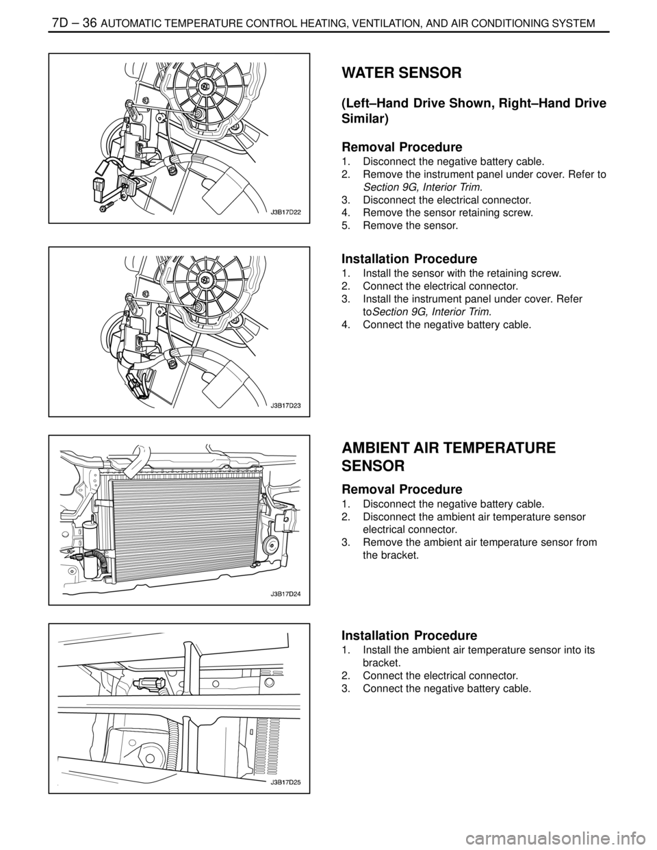
WATER SENSOR
(Left–Hand Drive Shown, Right–Hand Drive
Similar)
Removal Procedure
1. Disconnect the negative battery cable.
2. Remove the instrument panel under cover. Refer to
Section 9G, Interior Trim.
3. Disconnect the electrical connector.
4. Remove the sensor retaining screw.
5. Remove the sensor.
Installation Procedure
1. Install the sensor with the retaining screw.
2. Connect the electrical connector.
3. Install the instrument panel under cover. Refer
toSection 9G, Interior Trim.
4. Connect the negative battery cable.
AMBIENT AIR TEMPERATURE
SENSOR
Removal Procedure
1. Disconnect the negative battery cable.
2. Disconnect the ambient air temperature sensor
electrical connector.
3. Remove the ambient air temperature sensor from
the bracket.
Installation Procedure
1. Install the ambient air temperature sensor into its
bracket.
2. Connect the electrical connector.
3. Connect the negative battery cable.
Page 2092 of 2643

IAUTOMATIC TEMPERATURE CONTROL HEATING, VENTILATION, AND AIR CONDITIONING SYSTEM 7D – 37
DAEWOO V–121 BL4
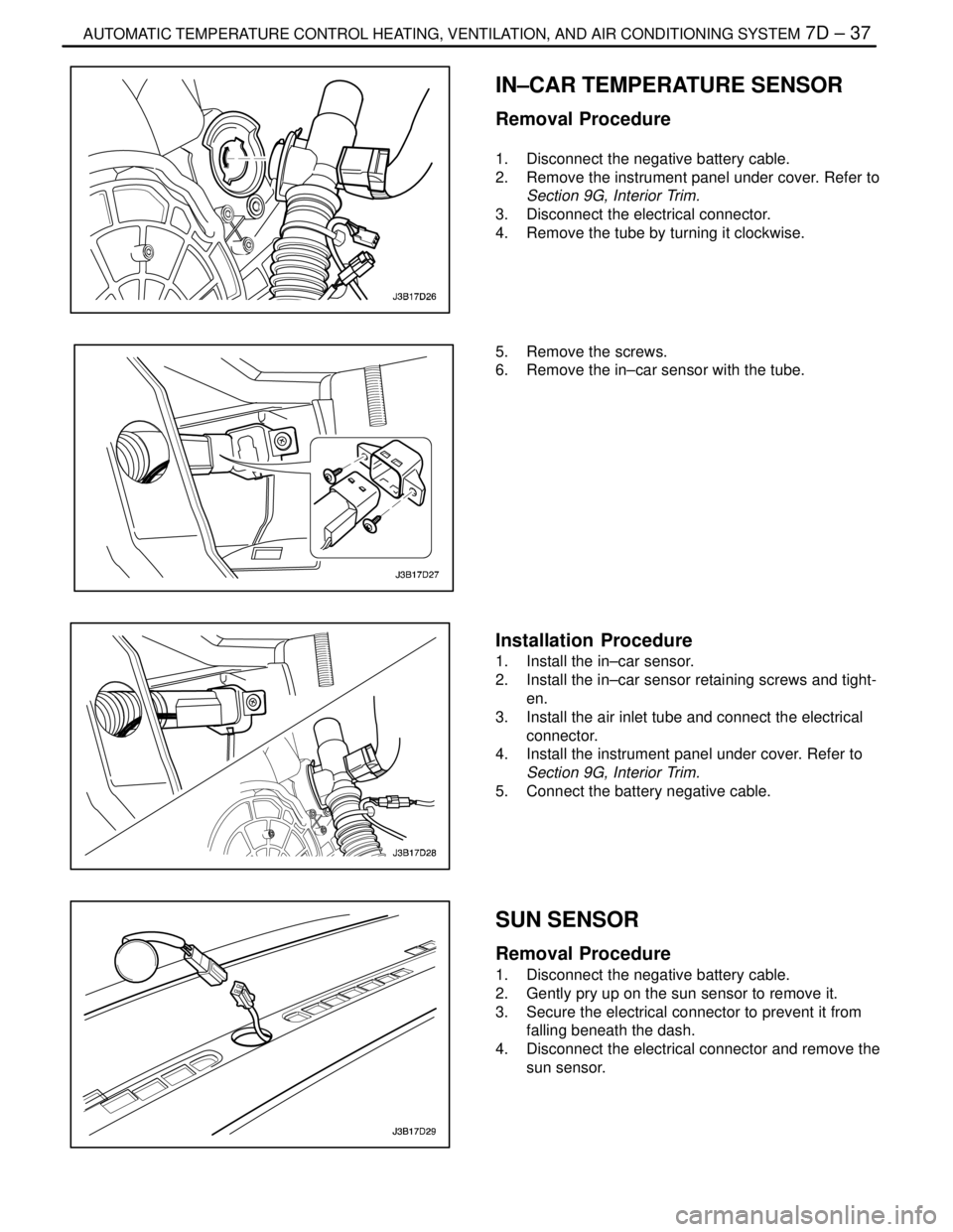
IN–CAR TEMPERATURE SENSOR
Removal Procedure
1. Disconnect the negative battery cable.
2. Remove the instrument panel under cover. Refer to
Section 9G, Interior Trim.
3. Disconnect the electrical connector.
4. Remove the tube by turning it clockwise.
5. Remove the screws.
6. Remove the in–car sensor with the tube.
Installation Procedure
1. Install the in–car sensor.
2. Install the in–car sensor retaining screws and tight-
en.
3. Install the air inlet tube and connect the electrical
connector.
4. Install the instrument panel under cover. Refer to
Section 9G, Interior Trim.
5. Connect the battery negative cable.
SUN SENSOR
Removal Procedure
1. Disconnect the negative battery cable.
2. Gently pry up on the sun sensor to remove it.
3. Secure the electrical connector to prevent it from
falling beneath the dash.
4. Disconnect the electrical connector and remove the
sun sensor.