Page 2418 of 2643
BUMPERS AND FASCIAS 9O – 7
DAEWOO V–121 BL4
Installation Procedure
1. Install the rear bumper fascia with the screws.
2. Install the bolts and the nuts in the luggage
compartment.
3. Install the luggage compartment wheelhouse trim
panels. Refer to Section 9G, Interior Trim.
4. Install the screws behind the fascia.
5. Install the splash shields with the screws.
6. Install the rear wheels. Refer to Section 2E, Tires
and Wheels.
REAR BUMPER IMPACT BAR
Removal Procedure
1. Remove the rear bumper fascia. Refer to ”Rear
Bumper Fascia” in this section.
2. Remove the screws and the impact bar.
Page 2462 of 2643

SECTION : 9R
BODY FRONT END
TABLE OF CONTENTS
SPECIFICATIONS9R–1 . . . . . . . . . . . . . . . . . . . . . . . . . .
Fastener Tightening Specifications 9R–1. . . . . . . . . . .
MAINTENANCE AND REPAIR9R–2 . . . . . . . . . . . . . . .
ON–VEHICLE SERVICE 9R–2. . . . . . . . . . . . . . . . . . . . .
Lubrication 9R–2. . . . . . . . . . . . . . . . . . . . . . . . . . . . . . . .
Fasteners 9R–2. . . . . . . . . . . . . . . . . . . . . . . . . . . . . . . .
Anticorrosion Materials 9R–2. . . . . . . . . . . . . . . . . . . . .
Front End Sealing 9R–2. . . . . . . . . . . . . . . . . . . . . . . . .
Cowl Vent Grille 9R–2. . . . . . . . . . . . . . . . . . . . . . . . . . .
Hood 9R–3. . . . . . . . . . . . . . . . . . . . . . . . . . . . . . . . . . . . . Hood Hinges 9R–3. . . . . . . . . . . . . . . . . . . . . . . . . . . . . .
Hood Prop Rod 9R–4. . . . . . . . . . . . . . . . . . . . . . . . . . . .
Hood Secondary Latch 9R–4. . . . . . . . . . . . . . . . . . . . .
Hood Latch Release Cable 9R–5. . . . . . . . . . . . . . . . . .
Notchback Radiator Grille 9R–5. . . . . . . . . . . . . . . . . . .
Hatchback Radiator Grille 9R–6. . . . . . . . . . . . . . . . . . .
Front Wheel Well Splash Shield 9R–6. . . . . . . . . . . . .
Fender 9R–7. . . . . . . . . . . . . . . . . . . . . . . . . . . . . . . . . . .
GENERAL DESCRIPTION AND SYSTEM
OPERATION9R–10 . . . . . . . . . . . . . . . . . . . . . . . . . . . . .
Body Front End 9R–10. . . . . . . . . . . . . . . . . . . . . . . . . .
SPECIFICATIONS
FASTENER TIGHTENING SPECIFICATIONS
ApplicationNSmLb–FtLb–In
A–Pillar Fender Bolt10–89
Fender Bolt (Front of Fascia)4–35
Front Bumper Fascia–to–Fender Bolt2.5–22
Hinge Bolts2720–
Hood–to–Hinge Bolts2720–
Hood Latch Bolts8–71
Hood Release Handle Nuts4–35
Lower Fender Bolt10–89
Radiator Grille Nuts4–35
Splash Shield screws2–18
Upper Fender Bolts10–89
Page 2467 of 2643
9R – 6IBODY FRONT END
DAEWOO V–121 BL4
Installation Procedure
1. Install the radiator grille with the screws and clips.
HATCHBACK RADIATOR GRILLE
Removal Procedure
1. Open the hood.
2. Remove the screws.
3. Pree the clips with the screw driver.
Installation Procedure
1. Install the radiator grille with the screws.
FRONT WHEEL WELL SPLASH
SHIELD
Removal Procedure
1. Raise and suitably support the vehicle.
2. Remove the front wheel. Refer to Section 2E, Tires
and Wheels.
3. Remove the front mud guard. Refer to Section 9M,
Exterior Trim.
4. Remove the screws and the front wheel well splash
shield.
Page 2468 of 2643
BODY FRONT END 9R – 7
DAEWOO V–121 BL4
Installation Procedure
1. Install the screws and the front wheel well splash
shield.
Tighten
Tighten the front wheel well splash shield screws to
2 NSm (18 lb–in).
2. Install the front mud guard. Refer to Section 9M,
Exterior Trim.
3. Install the front wheel. Refer to Section 2E, Tires
and Wheels.
4. Lower the vehicle.
FENDER
Removal Procedure
1. Remove the front wheel well splash shield. Refer to
”Front Wheel Well Splash Shield” in this section.
2. Reposition the front headlamp.
3. Remove the bolts securing the front fascia to the
fender.
4. Reposition the front fascia.
5. Remove the fender bolts behind the front fascia.
6. Remove the bolts at the base of the fender.
7. Open the front door and remove the bolt at the
base of the A–pillar.
Page 2470 of 2643
BODY FRONT END 9R – 9
DAEWOO V–121 BL4
6. Install the front fascia to its original position.
7. Install the bolts securing the front fascia to the
fender.
Tighten
Tighten the front fascia–to–fender bolts to 2.5 NSm
(22 lb–in).
8. Install the front headlamp to its original position.
9. Install the front wheel well splash shield. Refer to
”Front Wheel Well Splash Shield” in this section.
Page 2473 of 2643
9S – 2IBODY REAR END
DAEWOO V–121 BL4
MAINTENANCE AND REPAIR
ON–VEHICLE SERVICE
FUEL FILLER DOOR
Removal Procedure
1. Remove the screws and the fuel filler door.
Installation Procedure
Notice : Dissimilar metals in direct contact with each other
may corrode rapidly. Make sure to use the correct fasten-
ers to prevent premature corrosion.
1. Install the fuel filler door with the screws.
Tighten
Tighten the fuel filler door screws to 4 NSm (35 lb–in).
FUEL FILLER DOOR REMOTE
HANDLE AND CABLE
Removal Procedure
1. Open the luggage compartment.
2. Remove the luggage compartment wheelhouse trim
panels and the luggage compartment rear trim pan-
el. Refer to Section 9G, Interior Trim.
3. Disconnect the cable from the fuel filler door.
Page 2475 of 2643

9S – 4IBODY REAR END
DAEWOO V–121 BL4
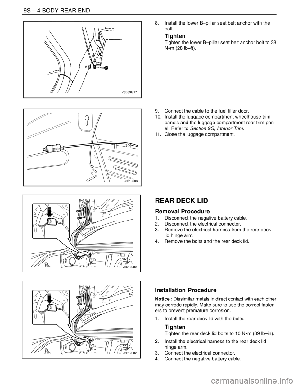
8. Install the lower B–pillar seat belt anchor with the
bolt.
Tighten
Tighten the lower B–pillar seat belt anchor bolt to 38
NSm (28 lb–ft).
9. Connect the cable to the fuel filler door.
10. Install the luggage compartment wheelhouse trim
panels and the luggage compartment rear trim pan-
el. Refer to Section 9G, Interior Trim.
11. Close the luggage compartment.
REAR DECK LID
Removal Procedure
1. Disconnect the negative battery cable.
2. Disconnect the electrical connector.
3. Remove the electrical harness from the rear deck
lid hinge arm.
4. Remove the bolts and the rear deck lid.
Installation Procedure
Notice : Dissimilar metals in direct contact with each other
may corrode rapidly. Make sure to use the correct fasten-
ers to prevent premature corrosion.
1. Install the rear deck lid with the bolts.
Tighten
Tighten the rear deck lid bolts to 10 NSm (89 lb–in).
2. Install the electrical harness to the rear deck lid
hinge arm.
3. Connect the electrical connector.
4. Connect the negative battery cable.
Page 2520 of 2643

1–12 GENERAL INFORMATIONNUBIRA/LACETTI
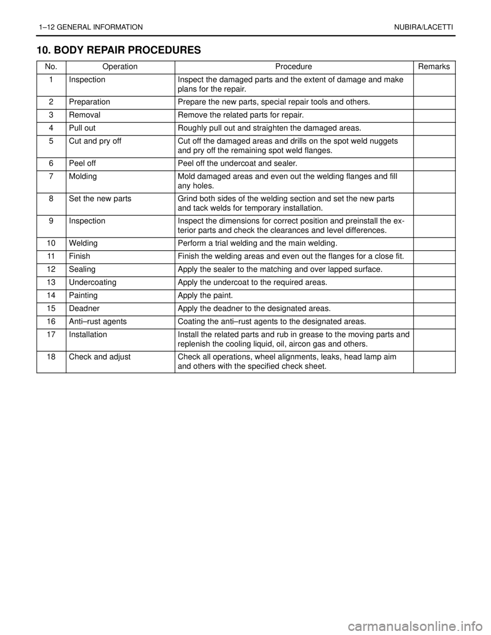
10. BODY REPAIR PROCEDURES
No.OperationProcedureRemarks
1InspectionInspect the damaged parts and the extent of damage and make
plans for the repair..
2PreparationPrepare the new parts, special repair tools and others..
3RemovalRemove the related parts for repair..
4Pull outRoughly pull out and straighten the damaged areas..
5Cut and pry offCut off the damaged areas and drills on the spot weld nuggets
and pry off the remaining spot weld flanges..
6Peel offPeel off the undercoat and sealer..
7MoldingMold damaged areas and even out the welding flanges and fill
any holes..
8Set the new partsGrind both sides of the welding section and set the new parts
and tack welds for temporary installation..
9InspectionInspect the dimensions for correct position and preinstall the ex-
terior parts and check the clearances and level differences..
10WeldingPerform a trial welding and the main welding..
11FinishFinish the welding areas and even out the flanges for a close fit..
12SealingApply the sealer to the matching and over lapped surface..
13UndercoatingApply the undercoat to the required areas..
14PaintingApply the paint..
15DeadnerApply the deadner to the designated areas..
16Anti–rust agentsCoating the anti–rust agents to the designated areas..
17InstallationInstall the related parts and rub in grease to the moving parts and
replenish the cooling liquid, oil, aircon gas and others..
18Check and adjustCheck all operations, wheel alignments, leaks, head lamp aim
and others with the specified check sheet..