Page 1582 of 2643

ZF 4 HP 16 AUTOMATIC TRANSAXLE 5A1 – 233
DAEWOO V–121 BL4
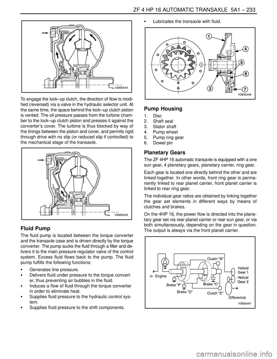
To engage the lock–up clutch, the direction of flow is modi-
fied (reversed) via a valve in the hydraulic selector unit. At
the same time, the space behind the lock–up clutch piston
is vented. The oil pressure passes from the turbine cham-
ber to the lock–up clutch piston and presses it against the
converter’s cover. The turbine is thus blocked by way of
the linings between the piston and cover, and permits rigid
through drive with no slip (or reduced slip if controlled) to
the mechanical stage of the transaxle.
Fluid Pump
The fluid pump is located between the torque converter
and the transaxle case and is driven directly by the torque
converter. The pump sucks the fluid through a filter and de-
livers it to the main pressure regulator valve of the control
system. Excess fluid flows back to the pump. The fluid
pump fulfills the following functions:
S Generates line pressure.
S Delivers fluid under pressure to the torque convert-
er, thus preventing air bubbles in the fluid.
S Induces a flow of fluid through the torque converter
in order to eliminate heat.
S Supplies fluid pressure to the hydraulic control sys-
tem.
S Supplies fluid pressure to the shift components.S Lubricates the transaxle with fluid.
Pump Housing
1. Disc
2. Shaft seal
3. Stator shaft
4. Pump wheel
5. Pump ring gear
6. Dowel pin
Planetary Gears
The ZF 4HP 16 automatic transaxle is equipped with a one
sun gear, 4 planetary gears, planetary carrier, ring gear.
Each gear is located one directly behind the other and are
linked together. In other words, front ring gear is perma-
nently linked to rear planet carrier, front planet carrier is
linked to rear ring gear.
The individual gear ratios are obtained by linking together
the gear set elements in different ways by means of
clutches and brakes.
On the 4HP 16, the power flow is directed into the plane-
tary gear set via rear planet carrier or rear sun gear, or via
both simultaneously, depending on the gear in question.
The output is always via the front planet carrier.
Page 1583 of 2643

5A1 – 234IZF 4 HP 16 AUTOMATIC TRANSAXLE
DAEWOO V–121 BL4
Shift Elements: Multi–disc Clutches and
Brakes
The purpose of the shift elements is to perform shifts un-
der load without the tractive flow being interrupted.
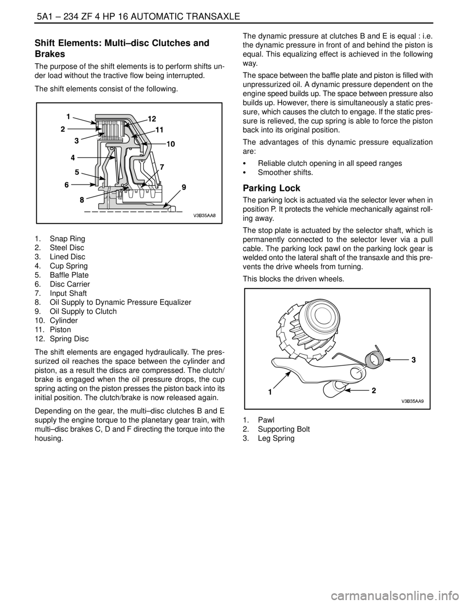
The shift elements consist of the following.
1. Snap Ring
2. Steel Disc
3. Lined Disc
4. Cup Spring
5. Baffle Plate
6. Disc Carrier
7. Input Shaft
8. Oil Supply to Dynamic Pressure Equalizer
9. Oil Supply to Clutch
10. Cylinder
11. Piston
12. Spring Disc
The shift elements are engaged hydraulically. The pres-
surized oil reaches the space between the cylinder and
piston, as a result the discs are compressed. The clutch/
brake is engaged when the oil pressure drops, the cup
spring acting on the piston presses the piston back into its
initial position. The clutch/brake is now released again.
Depending on the gear, the multi–disc clutches B and E
supply the engine torque to the planetary gear train, with
multi–disc brakes C, D and F directing the torque into the
housing.The dynamic pressure at clutches B and E is equal : i.e.
the dynamic pressure in front of and behind the piston is
equal. This equalizing effect is achieved in the following
way.
The space between the baffle plate and piston is filled with
unpressurized oil. A dynamic pressure dependent on the
engine speed builds up. The space between pressure also
builds up. However, there is simultaneously a static pres-
sure, which causes the clutch to engage. If the static pres-
sure is relieved, the cup spring is able to force the piston
back into its original position.
The advantages of this dynamic pressure equalization
are:
S Reliable clutch opening in all speed ranges
S Smoother shifts.
Parking Lock
The parking lock is actuated via the selector lever when in
position P. It protects the vehicle mechanically against roll-
ing away.
The stop plate is actuated by the selector shaft, which is
permanently connected to the selector lever via a pull
cable. The parking lock pawl on the parking lock gear is
welded onto the lateral shaft of the transaxle and this pre-
vents the drive wheels from turning.
This blocks the driven wheels.
1. Pawl
2. Supporting Bolt
3. Leg Spring
Page 1586 of 2643

ZF 4 HP 16 AUTOMATIC TRANSAXLE 5A1 – 237
DAEWOO V–121 BL4
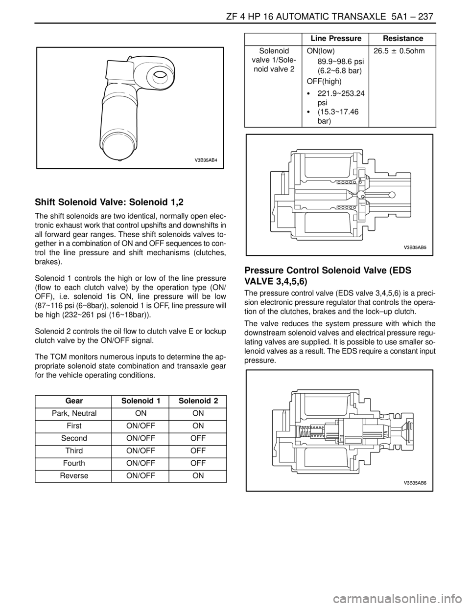
Shift Solenoid Valve: Solenoid 1,2
The shift solenoids are two identical, normally open elec-
tronic exhaust work that control upshifts and downshifts in
all forward gear ranges. These shift solenoids valves to-
gether in a combination of ON and OFF sequences to con-
trol the line pressure and shift mechanisms (clutches,
brakes).
Solenoid 1 controls the high or low of the line pressure
(flow to each clutch valve) by the operation type (ON/
OFF), i.e. solenoid 1is ON, line pressure will be low
(87~116 psi (6~8bar)), solenoid 1 is OFF, line pressure will
be high (232~261 psi (16~18bar)).
Solenoid 2 controls the oil flow to clutch valve E or lockup
clutch valve by the ON/OFF signal.
The TCM monitors numerous inputs to determine the ap-
propriate solenoid state combination and transaxle gear
for the vehicle operating conditions.
Gear
Solenoid 1Solenoid 2
Park, NeutralONON
FirstON/OFFON
SecondON/OFFOFF
ThirdON/OFFOFF
FourthON/OFFOFF
ReverseON/OFFON
Line PressureResistance
Solenoid
valve 1/Sole-
noid valve 2ON(low)
89.9~98.6 psi
(6.2~6.8 bar)
OFF(high)
S 221.9~253.24
psi
S (15.3~17.46
bar)26.5 ± 0.5ohm
Pressure Control Solenoid Valve (EDS
VALVE 3,4,5,6)
The pressure control valve (EDS valve 3,4,5,6) is a preci-
sion electronic pressure regulator that controls the opera-
tion of the clutches, brakes and the lock–up clutch.
The valve reduces the system pressure with which the
downstream solenoid valves and electrical pressure regu-
lating valves are supplied. It is possible to use smaller so-
lenoid valves as a result. The EDS require a constant input
pressure.
Page 1590 of 2643

ZF 4 HP 16 AUTOMATIC TRANSAXLE 5A1 – 241
DAEWOO V–121 BL4
TCM INPUTS THAT AFFECT THE 4HP
16 TRANSAXLE
Throttle Position Sensor
S Provides throttle position data to the TCM for deter-
mining shift patterns and TCC apply/release.
S An incorrect throttle position sensor input could
causes erratic or shift pattern, poor shift quality or
TCC function
Automatic Transaxle Output (Shaft) Speed
Sensor
S Provides vehicle speed data to the TCM for deter-
mining shift patterns and TCC apply/release, and
gear ratio calculations.
S An incorrect throttle position sensor input could
causes erratic or shift pattern, poor shift quality or
TCC function
Automatic Transaxle Input (Shaft) Speed
Sensor
S Provides transaxle input speed data to the TCM for
determining shift patterns and TCC apply/release,
and gear ratio.
Engine Coolant Temperature Sensor
S Provides coolant temperature data to the TCM for
determining initial TCC engagement.
S An incorrect engine coolant temperature sensor
input could causes an incorrect initial TCC apply
Engine Speed
S The ignition module provides engine speed data the
TCM.
S The TCM uses engine speed information for con-
trolling wide open throttle shifts and the TCC PWM
solenoid duty cycle.
Stoplamp Switch
S Provides brake apply information to the TCM for
controlling TCC apply and release.
S An incorrect TCC stoplamp switch input could
causes an incorrect TCC apply or release.
Transaxle Fluid Temperature (TFT) Sensor
S Provides transaxle fluid temperature information to
the TCM for determining alternate shift patterns and
TCC apply during high temperature conditions (hot
mode operation).
S An incorrect transaxle temperature sensor input
could causes altered shift patterns, poor shift quali-
ty and incorrect TCC apply.
Page 1595 of 2643
AISIN AUTOMATIC TRANSAXLE 5A2 – 5
DAEWOO V–121 BL4
SPECIAL TOOLS
SPECIAL TOOLS TABLE
DW260–021–02
Automatic
Transaxle
Overhaul
Fixture
DW240–020
Brake/Clutch
Spring Compressor
DW240–030
Forward Clutch
Adapter
DW240–040
Direct Clutch
Adapter
DW240–050
Overdrive
Brake Adapter
DW240–060–01
Brake Spring
Compressor
Bolt/Nut
DW240–060–02
Brake Spring
Compressor
Plate
DW240–070
1st/Reverse
Brake Adapter
Page 1596 of 2643
5A2 – 6IAISIN AUTOMATIC TRANSAXLE
DAEWOO V–121 BL4
DW240–080
2nd Brake Adapter
DW240–090
Planetary Ring
Gear Remover
DW240–100
Counter Drive
Gear Installation
Adapter
DW260–041
Planetary Ring
Gear Nut
Removal/Installation
Socket (52mm)
DW260–031–01
Tranaxle Housing
Oil Seal Installer
DW260–031–02
Tranaxle Case
Oil Seal Installer
DW240–120
Measuring Terminal
DW240–130
Differential Preload
Adapter
DW260–013
Transaxle Support
Fixture
DW240–140
Transaxle Housing
Side Bearing
Outer Race
Adapter
Page 1610 of 2643
5A2 – 20IAISIN AUTOMATIC TRANSAXLE
DAEWOO V–121 BL4
1. Transaxle Housing
2. Oil Seal
3. Oil Reservoir Plate
4. Transaxle Oil Apply Pipe
5. Differential Gear Oil Apply Pipe
6. Transaxle Oil Apply Pipe Clamp
7. Spring
8. Check Valve Pipe Clamp
9. Apply Gasket
10. Brake Drun Gasket
11. Transaxle Wire
12. O–ring
13. Valve Body
14. Parking Lock Pawl
15. Parking Lock Pawl Shaft
16. Torsion Spring
17. Manual Valve lever Shaft
18. Manual Valve Lever
19. Parking Lock Rod
20. Parking Lock Pawl Bracket
21. Manual Detent Spring
22. Pin
23. Spacer24. Oil Seal
25. Transmission Range (TR) Switch
26. Lock Washer
27. Control Lever
28. Washer
29. Gasket
30. Oil Strainer
31. Oil Pan
32. Gasket
33. Magnet
34. Direct Clutch Accumulator Piston
35. O–ring
36. Spring
37. O–ring
38. Forward Clutch Accumulator Piston
39. O–ring
40. Spring
41. O–ring
42. Overdrive Brake Accumulator Piston
43. O–ring
44. O–ring
45. Spring
Page 1612 of 2643

5A2 – 22IAISIN AUTOMATIC TRANSAXLE
DAEWOO V–121 BL4
1. Planetary Ring Gear
2. O–ring
3. 1st and Reverse Brake Piston
4. O–ring
5. 1st and Reverse Brake Piston Return Spring
6. Plate
7. Disc
8. Flange
9. Snap Ring
10. Planetary Gear
11. Thrust Washer
12. No. 2 One–Way Clutch
13. Anti–Rattle Clip
14. Flange
15. Disc
16. Plate
17. 2nd Brake Piston Return Spring
18. O–ring
19. 2nd Brake Piston
20. O–ring
21. 2nd Brake Clutch Cylinder
22. Snap Ring
23. Thrust Bearing Race
24. Front Planetary Sun Gear
25. Thrust Bearing Race26. One–Way Clutch Assembly
27. Thrust Washer
28. Rear Planetary Sun Gear
29. Snap Ring
30. Flange
31. Disc
32. Plate
33. Thrust Bearing Race
34. Thrust Needle Roller Bearing
35. Forward Clutch Hub
36. Thrust Bearing Race
37. Thrust Needle Roller Bearing
38. Thrust Bearing Race
39. Forward and Reverse Clutch Assembly
40. Thrust Needle Roller Bearing
41. Snap Ring
42. O/D Brake Return Spring
43. O/D Brake Piston
44. O–ring
45. Seal Ring
46. Transaxle Rear Cover
47. Apply Gasket
48. O–ring
49. Screw Plug