Page 1562 of 2643

ZF 4 HP 16 AUTOMATIC TRANSAXLE 5A1 – 213
DAEWOO V–121 BL4
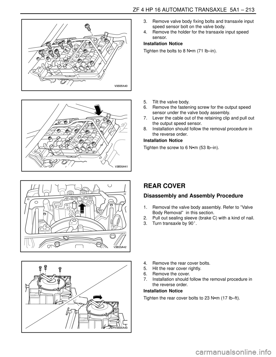
3. Remove valve body fixing bolts and transaxle input
speed sensor bolt on the valve body.
4. Remove the holder for the transaxle input speed
sensor.
Installation Notice
Tighten the bolts to 8 NSm (71 lb–in).
5. Tilt the valve body.
6. Remove the fastening screw for the output speed
sensor under the valve body assembly.
7. Lever the cable out of the retaining clip and pull out
the output speed sensor.
8. Installation should follow the removal procedure in
the reverse order.
Installation Notice
Tighten the screw to 6 NSm (53 lb–in).
REAR COVER
Disassembly and Assembly Procedure
1. Removal the valve body assembly. Refer to ”Valve
Body Removal” in this section.
2. Pull out sealing sleeve (brake C) with a kind of nail.
3. Turn transaxle by 90°.
4. Remove the rear cover bolts.
5. Hit the rear cover rightly.
6. Remove the cover.
7. Installation should follow the removal procedure in
the reverse order.
Installation Notice
Tighten the rear cover bolts to 23 NSm (17 lb–ft).
Page 1568 of 2643

ZF 4 HP 16 AUTOMATIC TRANSAXLE 5A1 – 219
DAEWOO V–121 BL4
Tools Required
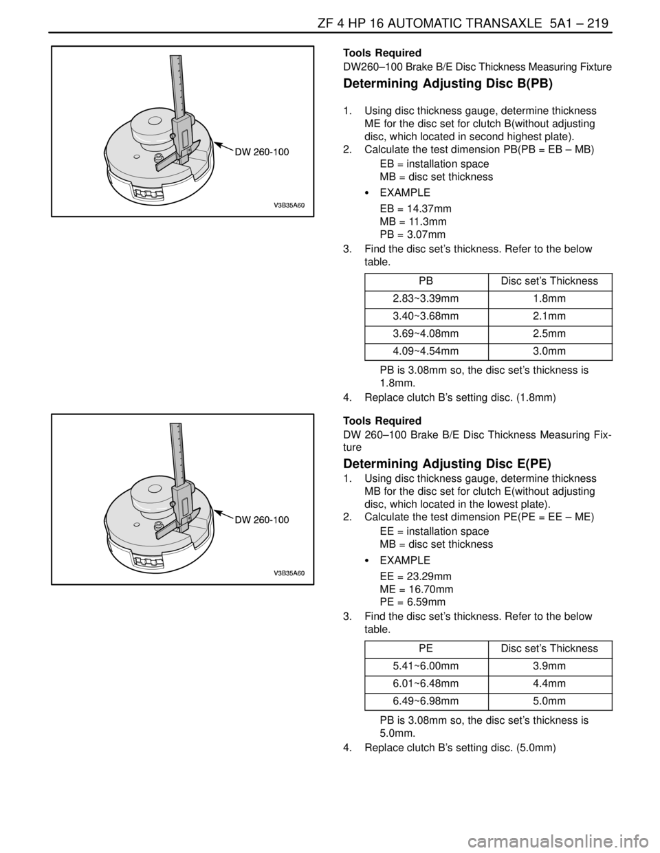
DW260–100 Brake B/E Disc Thickness Measuring Fixture
Determining Adjusting Disc B(PB)
1. Using disc thickness gauge, determine thickness
ME for the disc set for clutch B(without adjusting
disc, which located in second highest plate).
2. Calculate the test dimension PB(PB = EB – MB)
EB = installation space
MB = disc set thickness
S EXAMPLE
EB = 14.37mm
MB = 11.3mm
PB = 3.07mm
3. Find the disc set’s thickness. Refer to the below
table.
PB
Disc set’s Thickness
2.83~3.39mm1.8mm
3.40~3.68mm2.1mm
3.69~4.08mm2.5mm
4.09~4.54mm3.0mm
PB is 3.08mm so, the disc set’s thickness is
1.8mm.
4. Replace clutch B’s setting disc. (1.8mm)
Tools Required
DW 260–100 Brake B/E Disc Thickness Measuring Fix-
ture
Determining Adjusting Disc E(PE)
1. Using disc thickness gauge, determine thickness
MB for the disc set for clutch E(without adjusting
disc, which located in the lowest plate).
2. Calculate the test dimension PE(PE = EE – ME)
EE = installation space
MB = disc set thickness
S EXAMPLE
EE = 23.29mm
ME = 16.70mm
PE = 6.59mm
3. Find the disc set’s thickness. Refer to the below
table.
PE
Disc set’s Thickness
5.41~6.00mm3.9mm
6.01~6.48mm4.4mm
6.49~6.98mm5.0mm
PB is 3.08mm so, the disc set’s thickness is
5.0mm.
4. Replace clutch B’s setting disc. (5.0mm)
Page 1570 of 2643
ZF 4 HP 16 AUTOMATIC TRANSAXLE 5A1 – 221
DAEWOO V–121 BL4
6. Remove the axial needle bearing.
7. Take out front gear set with rear ring gear, front sun
gear and oil trays.
8. Take oil trays and front sun gear off the planetary
gear set.
9. Installation should follow the removal procedure in
the reverse order.
BRAKE C/D
Tools Required
DW260–160 Brake C/D Snap Ring Remover/Installer
Disassembly and Assembly Procedure
1. Take snap ring out of transaxle housing.
Page 1572 of 2643
ZF 4 HP 16 AUTOMATIC TRANSAXLE 5A1 – 223
DAEWOO V–121 BL4
6. Remove cylinder with piston C.
7. Separate between piston C and cylinder C.
8. Take snap ring out of brake C.
9. Remove the disc set C.
Installation Notice
S Transaxle has two lined clutch discs and one
steel clutch disc. The lined discs must be
installed in such a way that the lining faces the
steel disc.
S Insert the fitting keys into the appropriate
grooves.
Page 1574 of 2643
ZF 4 HP 16 AUTOMATIC TRANSAXLE 5A1 – 225
DAEWOO V–121 BL4
BRAKE F, SLOTTED NUT
Tools Required
DW260–060 Brake F Split Stop Ring Remover
Disassembly and Assembly Procedure
1. Remove the side shaft. Refer to ”Side Shaft” in this
section.
2. Take OFF the disc set and the brake F inner disc
carrier.
3. Mount fixture and remove the brake F split stop
ring.
4. Remove the fixture and take off the cup spring.
Page 1575 of 2643
5A1 – 226IZF 4 HP 16 AUTOMATIC TRANSAXLE
DAEWOO V–121 BL4
5. Release the piston F by applying compressed air to
the bore.
6. Remove piston F and bearing plate with spur gear.
7. Installation should follow the removal procedure in
the reverse order.
Removal Notice
Since the bearing set is tight, press the bearing plate up-
ward from underneath to remove it.
ORIGIN
ON/OFF– 12.54
+ / –
ORIGIN
ON/OFF– 12.54
+ / –
Tools Required
DW 260–110 Brake F Disc Clearance Measuring Bar
Measuring Installation Space F
1. Using a depth gauge, measuring from the transaxle
housing sealing surfaces to the piston’s disc sup-
port surface at two opposing points = M1, M2
2. Average the measurement values M1, M2 = BF
S CALCULATION
BF = (M1+M2)/2
S CALCULATION
M1 = 18.6mm
M2 = 18.8mm
BF = 18.7mm
Determining Adjusting Disc F
1. Calculate the test dimension PF (PF = BF – MF)
BF = installation space
MF = disc set thickness (assume 14.50mm)
S EXAMPLE
BF = 18.70mm
MF = 14.50mm
PE = 4.2mm
Page 1578 of 2643
ZF 4 HP 16 AUTOMATIC TRANSAXLE 5A1 – 229
DAEWOO V–121 BL4
PARKING LOCK SYSTEM
Disassembly and Assembly Procedure
1. Remove the parking lock assembly.
S Parking lock system is consist of parking pawl,
leg spring, support bolt.
2. Installation should follow the removal procedure in
the reverse order.
BEARING PLATE(WITH SPUR GEAR)
ASSEMBLY
Disassembly and Assembly Procedure
1. Remove the piston F. Refer to ”Brake F” in this
section.
2. Remove the bearing plate bolts and bearing plate.
3. Installation should follow the removal procedure in
the reverse order.
Installation Notice
Tighten
Tighten the bearing plate bolts to 27 NSm (17 lb–ft).
OIL PUMP ASSEMBLY
Disassembly and Assembly Procedure
1. Remove the oil pump housing bolts.
2. Using the plastic hammer. Take out the oil pump
housing.
Installation Notice
Tighten
Tighten the oil pump housing bolts 10 NSm (89 lb–in).
3. Remove the stator shaft bolts.
Page 1581 of 2643

5A1 – 232IZF 4 HP 16 AUTOMATIC TRANSAXLE
DAEWOO V–121 BL4
GENERAL DESCRIPTION
AND SYSTEM OPERATION
The ZF 4HP 16 automatic transaxle consists primarily of
the following components.
Mechanical
S Torque converter with TCC
S Drive link assembly
S Two multiple disk clutch assemblies : Clutch B,E
S Three multiple brake assemblies : Brake C,D,F
S Lock–up clutch valve
S Two planetary gear sets
S One oil pump
S Final drive and differential assembly
Electronic
S Two shift solenoid valve(sol.1,2)
S Four pressure control solenoid valve(EDS)
S Two speed sensors : A/T ISS and A/T OSS
S Fluid temperature sensor
S Automatic transaxle control module(TCM)
S Wiring harness assembly
MECHANICAL COMPONENTS
Torque Converter
The converter consists of the impeller, the turbine wheel,
the reaction member (stator) and the oil to transmit torque.
The impeller, which is driven by the engine, causes the oil
in the converter to flow in a circular pattern. This oil flow
meets the turbine wheel, where is direction of flow is de-
flected. At the hub, the oil leaves the turbine and reaches
the reaction member (stator), where it is once again de-
flected so that it reaches the impeller at the correct angle
of flow.
The reversal effect generates movement in the stator, the
reaction torque then amplifies the turbine torque.
The ratio between turbine torque and torque is referred to
as torque multiplication.
The greater the difference is speed between the pump and
turbine, the greater the torque multiplication; it is at its
highest when the turbine is at a standstill. The higher the
speed of the turbine, the lower the torque multiplication.
When the turbine speed reaches about 85%of the pump
speed, torque multiplication=1, i.e. the turbine torque
equivalent to pump torque.
The stator, which bears against the housing via the free-
wheel, is then rotating freely in the oil flow and the free-
wheel is over–come. From this point onwards, the con-
verter acts as a straightforward fluid coupling.
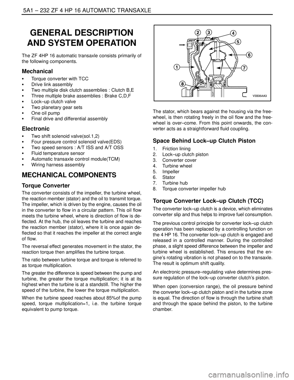
Space Behind Lock–up Clutch Piston
1. Friction lining
2. Lock–up clutch piston
3. Converter cover
4. Turbine wheel
5. Impeller
6. Stator
7. Turbine hub
8. Torque converter impeller hub
Torque Converter Lock–up Clutch (TCC)
The converter lock–up clutch is a device, which eliminates
converter slip and thus helps to improve fuel consumption.
The previous control principle for converter lock–up clutch
operation has been replaced by a controlling function on
the 4 HP 16. The converter lock–up clutch is engaged and
released in a controlled manner. During the controlled
phase, a slight speed difference between the impeller and
turbine wheel is established. This ensures that the en-
gine’s rotating vibration is not phased on to the transaxle.
The result is optimum shift quality.
An electronic pressure–regulating valve determines pres-
sure regulation of the lock–up converter clutch’s piston.
When open (conversion range), the oil pressure behind
the converter lock–up clutch piston and in the turbine zone
is equal. The direction of flow is through the turbine shaft
and through the space behind the piston, to the turbine
chamber.