2004 DAEWOO LACETTI Iat
[x] Cancel search: IatPage 2511 of 2643
NUBIRA/LACETTIGENERAL INFORMATION 1–3
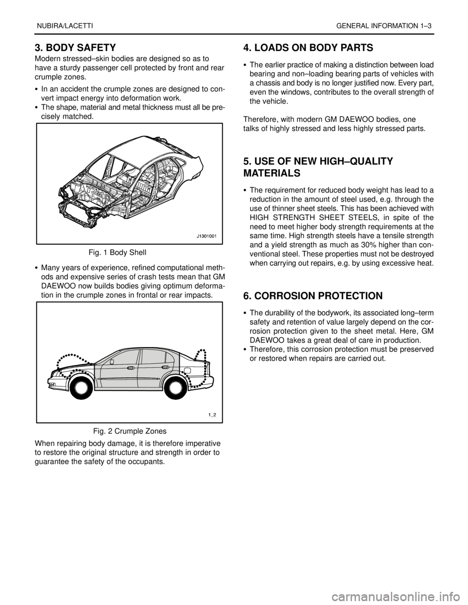
3. BODY SAFETY
Modern stressed–skin bodies are designed so as to
have a sturdy passenger cell protected by front and rear
crumple zones.
S In an accident the crumple zones are designed to con-
vert impact energy into deformation work.
S The shape, material and metal thickness must all be pre-
cisely matched.
Fig. 1 Body Shell
S Many years of experience, refined computational meth-
ods and expensive series of crash tests mean that GM
DAEWOO now builds bodies giving optimum deforma-
tion in the crumple zones in frontal or rear impacts.
Fig. 2 Crumple Zones
When repairing body damage, it is therefore imperative
to restore the original structure and strength in order to
guarantee the safety of the occupants.
4. LOADS ON BODY PARTS
S The earlier practice of making a distinction between load
bearing and non–loading bearing parts of vehicles with
a chassis and body is no longer justified now. Every part,
even the windows, contributes to the overall strength of
the vehicle.
.
Therefore, with modern GM DAEWOO bodies, one
talks of highly stressed and less highly stressed parts.
.
.
5. USE OF NEW HIGH–QUALITY
MATERIALS
S The requirement for reduced body weight has lead to a
reduction in the amount of steel used, e.g. through the
use of thinner sheet steels. This has been achieved with
HIGH STRENGTH SHEET STEELS, in spite of the
need to meet higher body strength requirements at the
same time. High strength steels have a tensile strength
and a yield strength as much as 30% higher than con-
ventional steel. These properties must not be destroyed
when carrying out repairs, e.g. by using excessive heat.
.
.
6. CORROSION PROTECTION
S The durability of the bodywork, its associated long–term
safety and retention of value largely depend on the cor-
rosion protection given to the sheet metal. Here, GM
DAEWOO takes a great deal of care in production.
S Therefore, this corrosion protection must be preserved
or restored when repairs are carried out.
Page 2524 of 2643

2–4 PREPARATIONS OF BODYWORK NUBIRA/LACETTI
2. CHECKPOINTS
S Accurate Inspection of Damaged Parts(Visual)
.
Seat Belts
Always replace the seat belt if :
1. The belt material is cut, punctured, burned or in any
way damaged.
2. The buckle or retractor does not work properly.
3. They were being worn at the time of a collision(also
check for damage at the seat belt anchor points).
4. Their condition is questionable.
.
Front Section :
1. Is there any bending, splitting, denting or other dam-
age to the suspension and its related parts?
2. Is there any deformation of the front panel or radiator
crossmember? Have any of the connected sections
come apart?
3. Are there any creases or distortion in the front wheel-
house or side frame? Have any of the connected sec-
tions come apart?
4. Is there any bending or twisting of the whole front
area?
5. Is there any deformation like creases, bulges, or dents
in the front pillar, dash panel, floor, etc.?
6. Is there any vertical twisting or misaligned clearance
in the door?
7. Is the windshield seal broken?
8. Is there any deformation in the vicinity of the top part
of the roof panel’s center pillar?
9. Is there any damage inside the automobile(is there
any twisting of the dash panel, or anything irregular with
the clearances or sheet–mounting parts)?
10. Is there any damage to the steering wheel? Is there
any deformation in the column and the column–mounted
parts?
11. Is there any oil or water leakage and damage to the en-
gine, transmission or brakes?
12. Is there any irregular noise in the gear changing opera-
tion, engine and transmission rotation?
13. Are there any traces of contact between the engine
block and the center crossmember ?
14. Is there any damage to brake or fuel lines, or wire har-
nesses?Rear Section :
1. Is there any twisting, bulging or denting of the rear floor
any rear bolsters? Have any of the connected sections
come apart?
2. Is there any irregular bulging or denting in the rear
fender?
3. Is there any distortion in the rear inner panel? Is there
any bending and denting in the vicinity of the rear pillar?
4. Is there any distortion or creasing is the rear wheel-
house and arch sections? Have any of the connected
sections come apart?
5. Is there anything irregular in the rear glass seal clear-
ance?
6. Is there any twisting or misalignment of the clearance
of the trunk lid opening section?
7. Is there any bending, splitting, denting or other dam-
age to the suspension and its related parts?
8. Is there any deformation of the rear floor crossmem-
ber, trunk floor panel and back panel? Have any of the
connected sections come apart?
.
Impact Beam :
Always replace the door assembly if :
1. The external force makes the impact beam of door in-
ner deform.
Always replace impact beam if :
2. The external force makes the impact beam of front
bumper and rear bumper deform.
Page 2526 of 2643
2–6 PREPARATIONS OF BODYWORK NUBIRA/LACETTI
4. MEASURING SYSTEMS (WITHOUT
SMALL DAMAGE)
S Whenever possible, make judgements and conclusions
based on measurement. Measure the wheel align-
ment(see pages 2–2, 2–3) so as to prevent any future
trouble like unsymmetrical wear of the tires or catchingof the steering wheel.
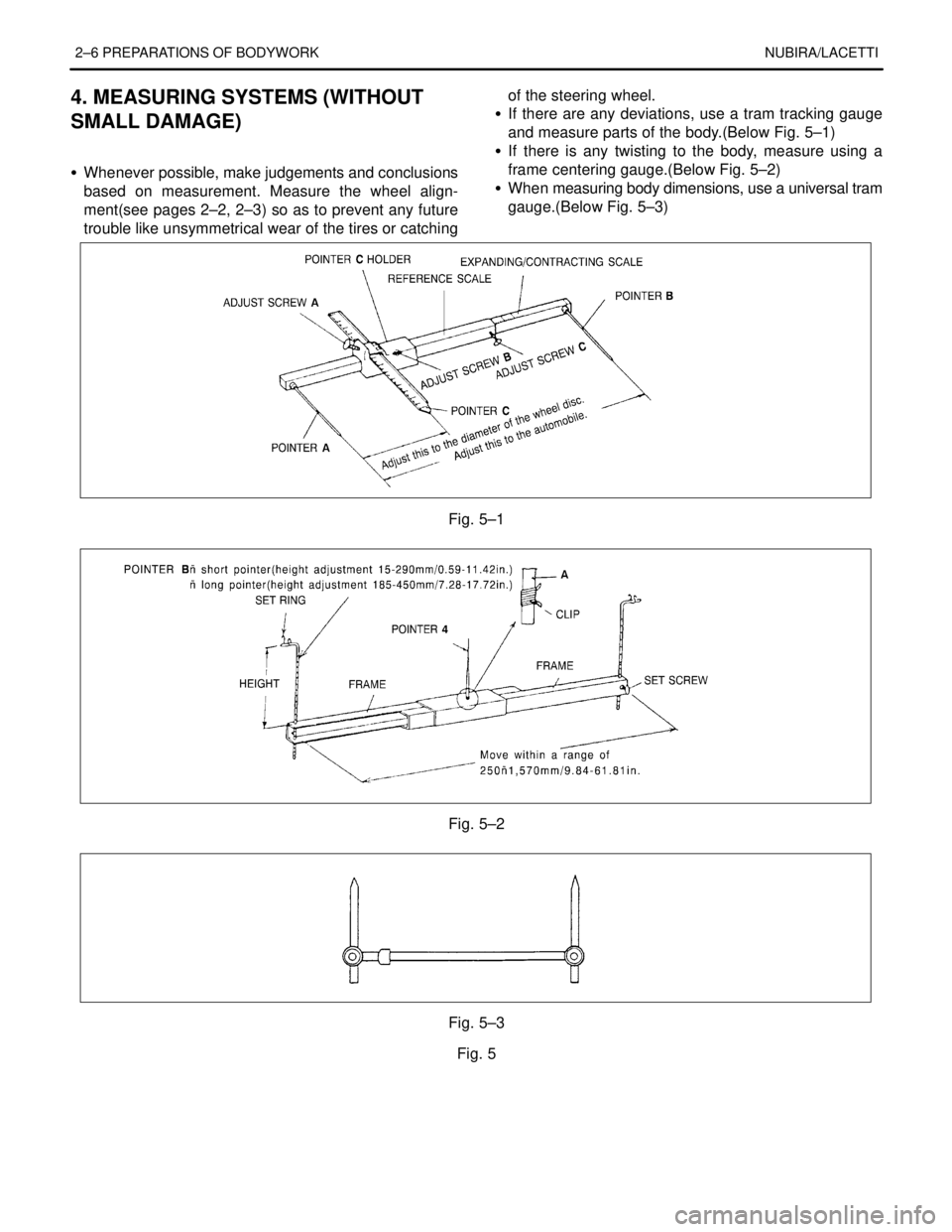
S If there are any deviations, use a tram tracking gauge
and measure parts of the body.(Below Fig. 5–1)
S If there is any twisting to the body, measure using a
frame centering gauge.(Below Fig. 5–2)
S When measuring body dimensions, use a universal tram
gauge.(Below Fig. 5–3)
.
Fig. 5–1
Fig. 5–2
Fig. 5–3
Fig. 5
Page 2537 of 2643
NUBIRA/LACETTIFRONT 4–3
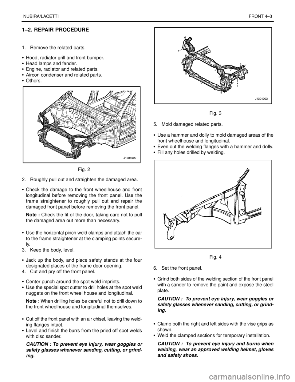
1–2. REPAIR PROCEDURE
1. Remove the related parts.
S Hood, radiator grill and front bumper.
S Head lamps and fender.
S Engine, radiator and related parts.
S Aircon condenser and related parts.
S Others.
Fig. 2
2. Roughly pull out and straighten the damaged area.
S Check the damage to the front wheelhouse and front
longitudinal before removing the front panel. Use the
frame straightener to roughly pull out and repair the
damaged front panel before removing the front panel.
Note : Check the fit of the door, taking care not to pull
the damaged area out more than necessary.
S Use the horizontal pinch weld clamps and attach the car
to the frame straightener at the clamping points secure-
ly.
3. Keep the body, level.
S Jack up the body, and place safety stands at the four
designated places of the frame door opening.
4. Cut and pry off the front panel.
S Center punch around the spot weld imprints.
S Use the special spot cutter to drill holes at the spot weld
nuggets on the front wheel house and longitudinal.
Note : When drilling holes be careful not to drill down to
the front wheelhouse and longitudinal themselves.
S Cut off the front panel with an air chisel, leaving the weld-
ing flanges intact.
S Level and finish the burrs from the pried off spot welds
with disc sander.
CAUTION : To prevent eye injury, wear goggles or
safety glasses whenever sanding, cutting, or grind-
ing.
Fig. 3
5. Mold damaged related parts.
S Use a hammer and dolly to mold damaged areas of the
front wheelhouse and longitudinal.
S Even out the welding flanges with a hammer and dolly.
S Fill any holes drilled by welding.
Fig. 4
6. Set the front panel.
S Grind both sides of the welding section of the front panel
with a sander to remove the paint and expose the steel
plate.
CAUTION : To prevent eye injury, wear goggles or
safety glasses whenever sanding, cutting, or grind-
ing.
S Clamp both the right and left sides with the vise grips as
shown.
S Weld the clamped sections for temporary installation.
CAUTION : To prevent eye injury and burns when
welding, wear an approved welding helmet, gloves
and safety shoes.
Page 2538 of 2643
4–4 FRONTNUBIRA/LACETTI
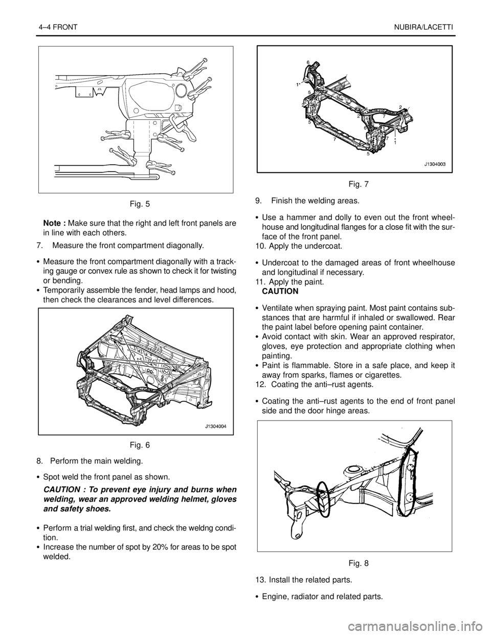
Fig. 5
Note : Make sure that the right and left front panels are
in line with each others.
7. Measure the front compartment diagonally.
S Measure the front compartment diagonally with a track-
ing gauge or convex rule as shown to check it for twisting
or bending.
S Temporarily assemble the fender, head lamps and hood,
then check the clearances and level differences.
Fig. 6
8. Perform the main welding.
S Spot weld the front panel as shown.
CAUTION : To prevent eye injury and burns when
welding, wear an approved welding helmet, gloves
and safety shoes.
S Perform a trial welding first, and check the weldng condi-
tion.
S Increase the number of spot by 20% for areas to be spot
welded.
Fig. 7
9. Finish the welding areas.
S Use a hammer and dolly to even out the front wheel-
house and longitudinal flanges for a close fit with the sur-
face of the front panel.
10. Apply the undercoat.
S Undercoat to the damaged areas of front wheelhouse
and longitudinal if necessary.
11. Apply the paint.
CAUTION
S Ventilate when spraying paint. Most paint contains sub-
stances that are harmful if inhaled or swallowed. Rear
the paint label before opening paint container.
S Avoid contact with skin. Wear an approved respirator,
gloves, eye protection and appropriate clothing when
painting.
S Paint is flammable. Store in a safe place, and keep it
away from sparks, flames or cigarettes.
12. Coating the anti–rust agents.
S Coating the anti–rust agents to the end of front panel
side and the door hinge areas.
Fig. 8
13. Install the related parts.
S Engine, radiator and related parts.
Page 2539 of 2643

NUBIRA/LACETTIFRONT 4–5
S Aircon condenser and related parts.
S Head lamps and fenders.
S Hood, radiator grill, and bumper.
S Others
S Install in the reverse order in which they were removed.
Note : After install the all related parts, rub in grease to
the moving parts and replenish cooling liquid, break oil,
aircon gas and others.
14. Check and adjust
S Check clearances and level differences.
S Check the hood locking and unlocking condition.
S Adjust the head lamp aim.
S Check all operation.
S Check for gas, oil and liquid leaks.
Note : Use specified check sheet for operation check
properly.
Page 2543 of 2643
NUBIRA/LACETTIFRONT 4–9
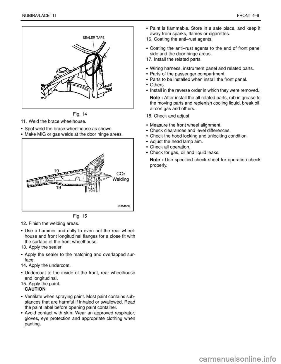
Fig. 14
11. Weld the brace wheelhouse.
S Spot weld the brace wheelhouse as shown.
S Make MIG or gas welds at the door hinge areas.
Fig. 15
12. Finish the welding areas.
S Use a hammer and dolly to even out the rear wheel-
house and front longitudinal flanges for a close fit with
the surface of the front wheelhouse.
13. Apply the sealer
S Apply the sealer to the matching and overlapped sur-
face.
14. Apply the undercoat.
S Undercoat to the inside of the front, rear wheelhouse
and longitudinal.
15. Apply the paint.
CAUTION
S Ventilate when spraying paint. Most paint contains sub-
stances that are harmful if inhaled or swallowed. Read
the paint label before opening paint container.
S Avoid contact with skin. Wear an approved respirator,
gloves, eye protection and appropriate clothing when
panting.S Paint is flammable. Store in a safe place, and keep it
away from sparks, flames or cigarettes.
16. Coating the anti–rust agents.
S Coating the anti–rust agents to the end of front panel
side and the door hinge areas.
17. Install the related parts.
S Wiring harness, instrument panel and related parts.
S Parts of the passenger compartment.
S Parts to be installed when install the front panel.
S Others.
S Install in the reverse order in which they were removed..
Note : After install the all related parts, rub in grease to
the moving parts and replenish cooling liquid, break oil,
aircon gas and others.
18. Check and adjust
S Measure the front wheel alignment.
S Check clearances and level differences.
S Check the hood locking and unlocking condition.
S Adjust the head lamp aim.
S Check all operation.
S Check for gas, oil and liquid leaks.
Note : Use specified check sheet for operation check
properly.
Page 2546 of 2643

4–12 FRONTNUBIRA/LACETTI
Note : Use of jigs is recommended for correct positions
and check that the both front longitudinal and wheel-
house are parallel.
S Tack weld the clamped section for temporary installa-
tion.
7. Perform the main welding.
S Weld as much as possible with the jig still mounted.
S Make MIG or gas welds at the butt joints at the front lon-
gitudinal, carefully.
Fig. 19
S Spot weld the wheelhouse with the front longitudinal
flange areas and front panel.
CAUTION : To prevent eye injury and burns when
welding, wear an approved welding helmet, gloves
and safety shoes.
S Perform a trial welding first, and check the welding con-
dition.
S Increase the number of spot by 20% for areas to be spot
welded.
Fig. 20
S Level the weld beads at the longitudinal butt joints area
with disc sander.
S Make the stiffener(Thickness: 2.8 mm Min., Width: 80
mm) according to the form of longitudinal butt joint areasand weld the stiffener at the longitudinal butt joint areas
with MIG welder.
Fig. 21
8. Finish the welding areas.
S Level the gas or MIG welded areas with disc sander.
S Use a hammer and dolly to even out the wheelhouse and
longitudinal flanges for a close fit.
9. Apply the sealer.
S Apply the sealer to the joint areas of the dash panel lower
and floor panel areas.
10. Apply the undercoat.
S Undercoat to the joint and overlapped areas of the front
floor, longitudinal under side and the inside of front, rear
wheelhouse.
11. Apply the paint.
CAUTION
S Ventilate when spraying paint. Most paint contains sub-
stances that are harmful if inhaled or swallowed. Read
the paint label before opening paint container.
S Avoid contact with skin. Wear an approved respirator,
gloves, eye protection and appropriate clothing when
painting.
S Paint is flammable. Store in a safe place, and keep it
away from sparks, flames or cigarettes.
12. Coating the anti–rust agents.
S Coating the anti–rust agents to the end of front panel
side and the front door hinge areas.
13. Install the related parts.
S Clean the passenger compartment.
S Wiring harness, instrument panel and related parts.
S Parts of the passenger compartment.
S Chassis components.
S Engine, radiator and related parts.
S Aircon condenser and related parts.
S Head lamps and fenders.
S Heed, radiator grill, and bumper.
S Others.
S Install in the reverse order in which they were removed.