2004 DAEWOO LACETTI Iat
[x] Cancel search: IatPage 2442 of 2643

9P – 22IDOORS
DAEWOO V–121 BL4
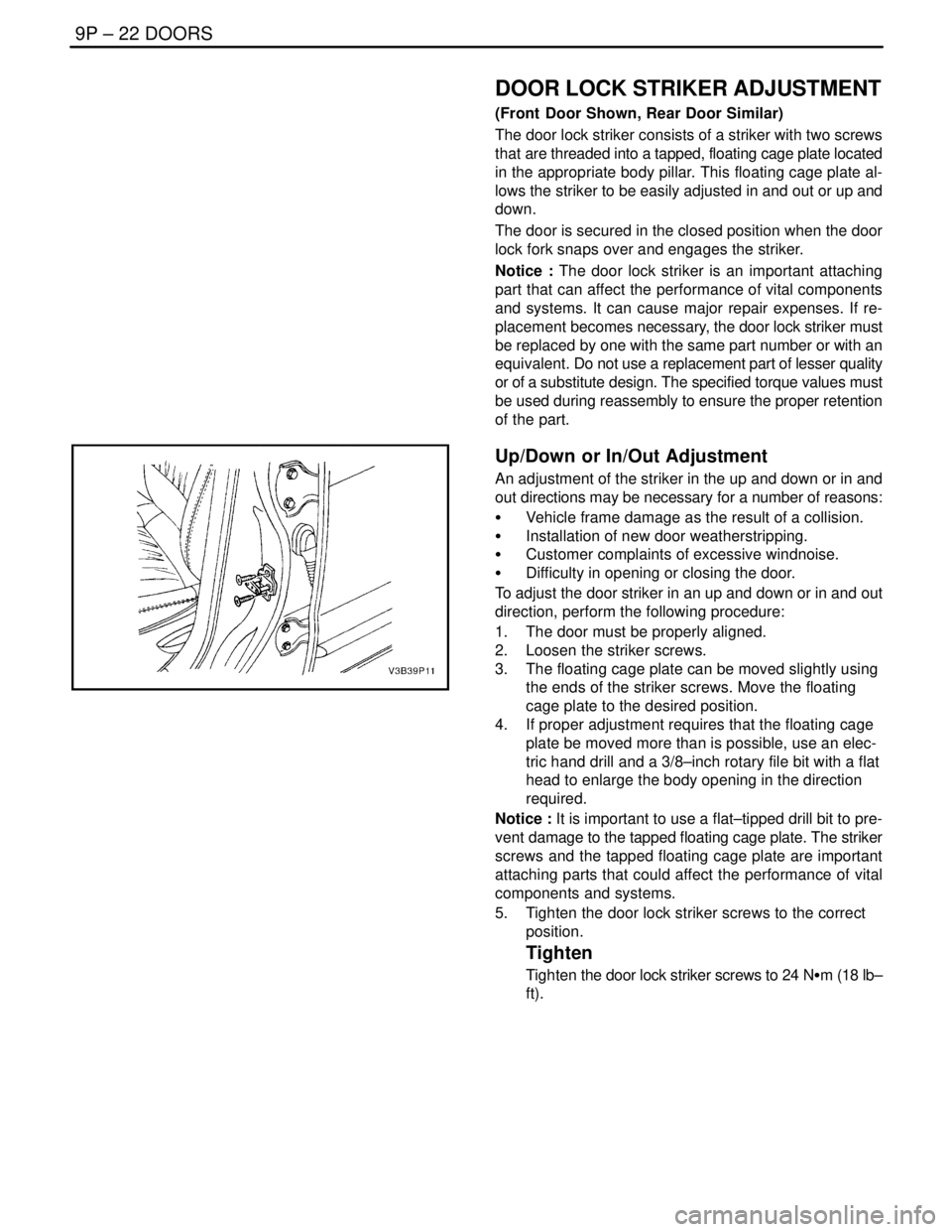
DOOR LOCK STRIKER ADJUSTMENT
(Front Door Shown, Rear Door Similar)
The door lock striker consists of a striker with two screws
that are threaded into a tapped, floating cage plate located
in the appropriate body pillar. This floating cage plate al-
lows the striker to be easily adjusted in and out or up and
down.
The door is secured in the closed position when the door
lock fork snaps over and engages the striker.
Notice : The door lock striker is an important attaching
part that can affect the performance of vital components
and systems. It can cause major repair expenses. If re-
placement becomes necessary, the door lock striker must
be replaced by one with the same part number or with an
equivalent. Do not use a replacement part of lesser quality
or of a substitute design. The specified torque values must
be used during reassembly to ensure the proper retention
of the part.
Up/Down or In/Out Adjustment
An adjustment of the striker in the up and down or in and
out directions may be necessary for a number of reasons:
S Vehicle frame damage as the result of a collision.
S Installation of new door weatherstripping.
S Customer complaints of excessive windnoise.
S Difficulty in opening or closing the door.
To adjust the door striker in an up and down or in and out
direction, perform the following procedure:
1. The door must be properly aligned.
2. Loosen the striker screws.
3. The floating cage plate can be moved slightly using
the ends of the striker screws. Move the floating
cage plate to the desired position.
4. If proper adjustment requires that the floating cage
plate be moved more than is possible, use an elec-
tric hand drill and a 3/8–inch rotary file bit with a flat
head to enlarge the body opening in the direction
required.
Notice : It is important to use a flat–tipped drill bit to pre-
vent damage to the tapped floating cage plate. The striker
screws and the tapped floating cage plate are important
attaching parts that could affect the performance of vital
components and systems.
5. Tighten the door lock striker screws to the correct
position.
Tighten
Tighten the door lock striker screws to 24 NSm (18 lb–
ft).
Page 2462 of 2643

SECTION : 9R
BODY FRONT END
TABLE OF CONTENTS
SPECIFICATIONS9R–1 . . . . . . . . . . . . . . . . . . . . . . . . . .
Fastener Tightening Specifications 9R–1. . . . . . . . . . .
MAINTENANCE AND REPAIR9R–2 . . . . . . . . . . . . . . .
ON–VEHICLE SERVICE 9R–2. . . . . . . . . . . . . . . . . . . . .
Lubrication 9R–2. . . . . . . . . . . . . . . . . . . . . . . . . . . . . . . .
Fasteners 9R–2. . . . . . . . . . . . . . . . . . . . . . . . . . . . . . . .
Anticorrosion Materials 9R–2. . . . . . . . . . . . . . . . . . . . .
Front End Sealing 9R–2. . . . . . . . . . . . . . . . . . . . . . . . .
Cowl Vent Grille 9R–2. . . . . . . . . . . . . . . . . . . . . . . . . . .
Hood 9R–3. . . . . . . . . . . . . . . . . . . . . . . . . . . . . . . . . . . . . Hood Hinges 9R–3. . . . . . . . . . . . . . . . . . . . . . . . . . . . . .
Hood Prop Rod 9R–4. . . . . . . . . . . . . . . . . . . . . . . . . . . .
Hood Secondary Latch 9R–4. . . . . . . . . . . . . . . . . . . . .
Hood Latch Release Cable 9R–5. . . . . . . . . . . . . . . . . .
Notchback Radiator Grille 9R–5. . . . . . . . . . . . . . . . . . .
Hatchback Radiator Grille 9R–6. . . . . . . . . . . . . . . . . . .
Front Wheel Well Splash Shield 9R–6. . . . . . . . . . . . .
Fender 9R–7. . . . . . . . . . . . . . . . . . . . . . . . . . . . . . . . . . .
GENERAL DESCRIPTION AND SYSTEM
OPERATION9R–10 . . . . . . . . . . . . . . . . . . . . . . . . . . . . .
Body Front End 9R–10. . . . . . . . . . . . . . . . . . . . . . . . . .
SPECIFICATIONS
FASTENER TIGHTENING SPECIFICATIONS
ApplicationNSmLb–FtLb–In
A–Pillar Fender Bolt10–89
Fender Bolt (Front of Fascia)4–35
Front Bumper Fascia–to–Fender Bolt2.5–22
Hinge Bolts2720–
Hood–to–Hinge Bolts2720–
Hood Latch Bolts8–71
Hood Release Handle Nuts4–35
Lower Fender Bolt10–89
Radiator Grille Nuts4–35
Splash Shield screws2–18
Upper Fender Bolts10–89
Page 2465 of 2643

9R – 4IBODY FRONT END
DAEWOO V–121 BL4
Installation Procedure
Notice : Dissimilar metals in direct contact with each other
may corrode rapidly. Make sure to use the correct fasten-
ers to prevent premature corrosion.
1. Install the hinge with the bolts.
Tighten
Tighten the hinge bolts to 27 NSm (20 lb–ft).
2. Install the hood. Refer to ”Hood” in this section.
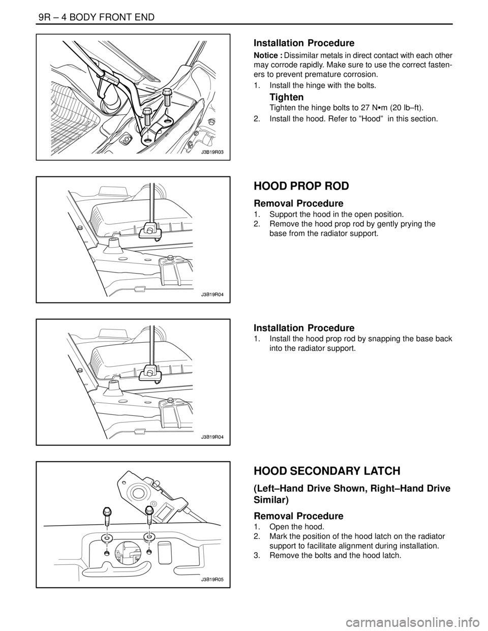
HOOD PROP ROD
Removal Procedure
1. Support the hood in the open position.
2. Remove the hood prop rod by gently prying the
base from the radiator support.
Installation Procedure
1. Install the hood prop rod by snapping the base back
into the radiator support.
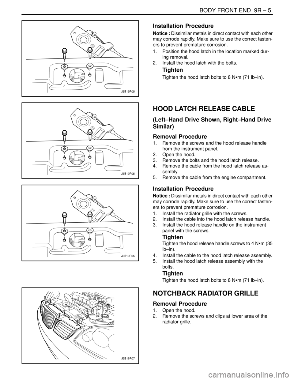
HOOD SECONDARY LATCH
(Left–Hand Drive Shown, Right–Hand Drive
Similar)
Removal Procedure
1. Open the hood.
2. Mark the position of the hood latch on the radiator
support to facilitate alignment during installation.
3. Remove the bolts and the hood latch.
Page 2466 of 2643

BODY FRONT END 9R – 5
DAEWOO V–121 BL4
Installation Procedure
Notice : Dissimilar metals in direct contact with each other
may corrode rapidly. Make sure to use the correct fasten-
ers to prevent premature corrosion.
1. Position the hood latch in the location marked dur-
ing removal.
2. Install the hood latch with the bolts.
Tighten
Tighten the hood latch bolts to 8 NSm (71 lb–in).
HOOD LATCH RELEASE CABLE
(Left–Hand Drive Shown, Right–Hand Drive
Similar)
Removal Procedure
1. Remove the screws and the hood release handle
from the instrument panel.
2. Open the hood.
3. Remove the bolts and the hood latch release.
4. Remove the cable from the hood latch release as-
sembly.
5. Remove the cable from the engine compartment.
Installation Procedure
Notice : Dissimilar metals in direct contact with each other
may corrode rapidly. Make sure to use the correct fasten-
ers to prevent premature corrosion.
1. Install the radiator grille with the screws.
2. Install the cable into the hood latch release handle.
3. Install the hood release handle on the instrument
panel with the screws.
Tighten
Tighten the hood release handle screws to 4 NSm (35
lb–in).
4. Install the cable to the hood latch release assembly.
5. Install the hood latch release assembly with the
bolts.
Tighten
Tighten the hood latch bolts to 8 NSm (71 lb–in).
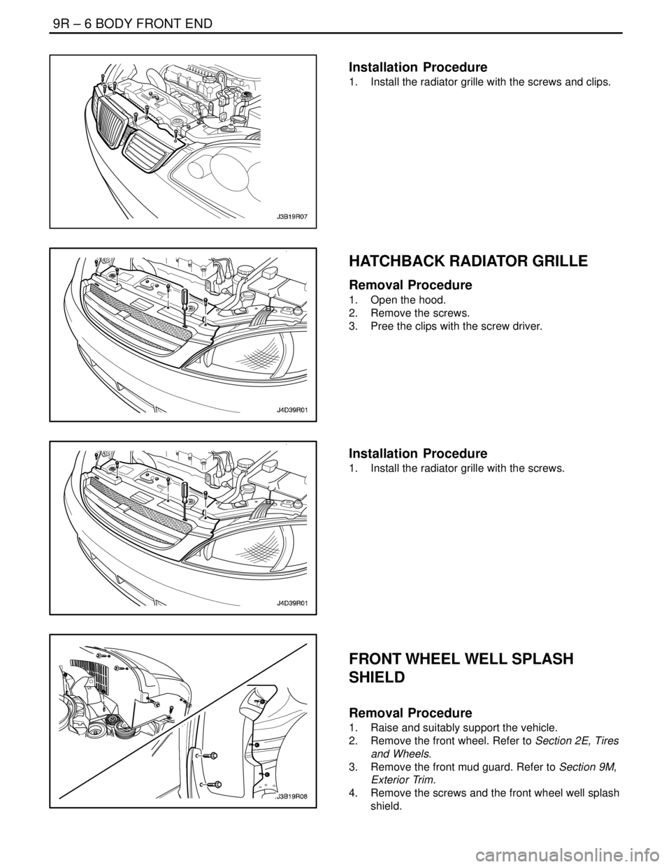
NOTCHBACK RADIATOR GRILLE
Removal Procedure
1. Open the hood.
2. Remove the screws and clips at lower area of the
radiator grille.
Page 2467 of 2643

9R – 6IBODY FRONT END
DAEWOO V–121 BL4
Installation Procedure
1. Install the radiator grille with the screws and clips.
HATCHBACK RADIATOR GRILLE
Removal Procedure
1. Open the hood.
2. Remove the screws.
3. Pree the clips with the screw driver.
Installation Procedure
1. Install the radiator grille with the screws.
FRONT WHEEL WELL SPLASH
SHIELD
Removal Procedure
1. Raise and suitably support the vehicle.
2. Remove the front wheel. Refer to Section 2E, Tires
and Wheels.
3. Remove the front mud guard. Refer to Section 9M,
Exterior Trim.
4. Remove the screws and the front wheel well splash
shield.
Page 2471 of 2643

9R – 10IBODY FRONT END
DAEWOO V–121 BL4
GENERAL DESCRIPTION
AND SYSTEM OPERATION
BODY FRONT END
This vehicle has a unitized body with a frame assembly
supporting the engine and the transaxle. The fender pan-
els and the radiator support are also integral parts of the
body.
Page 2488 of 2643

REMOTE KEYLESS ENTRY AND ANTI–THEFT SYSTEM 9T1 – 7
DAEWOO V–121 BL4
REMOTE KEYLESS ENTRY
TRANSMITTER PROGRAMMING
The Remote Keyless Entry System allows for the use of
as many as four(4) transmitters for each vehicle. Replace-
ment Remote Keyless Entry System Transmitters must
first be programmend to specific vehicle using the
Scan100 Secan tool.
This process is completed using serial data communica-
tion between the Scan 100 Scan tool and the Remote Key-
less Entry Control Unit and is the only method available for
programming Transmitters.
Notice : All Transmitters for a specific vehicle must be pro-
grammed at same time.
Notice : Once the programming function of the Remote
Keyless Entry System is activated, any Transmitter(exist-
ing or new) that is not programmed(or reprogrammed)
during the programming procedure will no longer operate
the Remote Keyless Entry System of that vehicle.
Notice : Ensure that the doors, hood and trunk/rear hatch
are closed prior to starting the programming procedure.
1. Connect the Scan 100 Scan Tool to the Data Link
Connector(DLC)
2. Turn the Scan 100 Scan Tool ”ON” by pressing the
”Power” Button, then wait for the MAIN MENU
screen to be displayed.
3. From the MAIN MENU screen, select ”Diagnostics”
by pressing #1 on the Key Pad.
4. From the MODEL YEAR screen, select the ap-
propriate model year of the specific vehicle by ei-
ther scrolling down to the year and pressing ”EN-
TER”, or by pressing the respective item number on
the Key Pad.
5. From the VEHICLE TYPE screen, select the specif-
ic vehicle model by either scrolling down to the
model name and pressing ”ENTER”, or by pressing
the respective item number on the Key Pad.
6. From the SYSTEM SELECTION MENU screen,
select ”Body” by pressing #2 on the Key Pad.
7. From the BODY SELECTION MENU screen, select
”Coding” by pressing #2 on the Key Pad.8. From the CODY SELECTION MENU screen, select
”Coding” by pressing #1 on the Key Pad.
9. From the SECRET NUMBER OF CODINGS
screen, enter for(4) zero’s (0–0–0–0) in the for(4)
boxes labeled ”1–2–3–4–”.
10. From the CODING SYSTEM SELECT screen, se-
lect ”Keyless Entry” by pressing #2 on the Key Pad.
Notice : A slight delay may occur and ”PLEASE WAIT”
may be displayed before the next screen appears.
11. From the KEYLESS ENTRY CODING SYSTEM
screen, select ”Coding Transmitter” by pressing #1
on the Key Pad.
12. When directed by the Scan 100 Scan Tool, press
any Button on the first Transmitter to be pro-
grammed.
CAUTION : Ensure that Transmitters from other ve-
hicles in the immediate area are not activated during
this procedure.
13. Continue programming Transmitters when directed
by the Scan 100 Scan Tool until all Transmitters
have been programmed.
Notice : A maximum of four(4) Transmitters may be pro-
grammed to a vehicle.
14. Once all Transmitters have been programmed,
press the ”ESC” Button on the Key Pad. The dis-
play will confirm the number of Transmitters pro-
grammed. If the number displayed does not match
the number of Transmitters programmed, repeat
the procedure.
15. Turn the Scan 100 Scan Tool ”OFF” by pressing the
”POWER” Button, then disconnect it from the Data
Link Connector.
16. Wait approximately 10 seconds, then test the op-
eration of each programmed Transmitter to ensure
it operates properly.
The control module/receiver leaves the programming
mode automatically and switches to the normal operating
mode when either of the following conditions occurs:
S the scan tool is disconnected from the ALDL.
S Four passwords are recorded in the control module/
receiver.
Page 2502 of 2643

9T2 – 12IIMMOBILIZER ANTI–THEFT SYSTEM
DAEWOO V–121 BL4
The VIN code is transmitted from the Immobilizer in the re-
lease message communication only incase of using an au-
thorized key. Without an authorized key it is not possible
to getthe system VIN code.In case of ECM internal state
is in Virgin mode or neutral mode the ECM learns the sys-
tem VIN code automatically after receiving the first release
response message.
To get a synchronized Immobilizer system (same VIN–
code in Immobilizer and ECM,authorized key) the DLC
test equipment has to be used for authorization of the
keys(first key coding). The usage of this test equipment is
restricted to authorized persons.
S Communication with the DLC–test equipment. Main
functions are the key coding procedure, the VIN–
code handling and the support for system test func-
tions.
S Handling of the software watchdog
Operation
In the active mode of immobilizer (engine OFF, IG key
OFF) the status LED isblinking as mode A. When ignition
is turned ON, the system wakes up and tries to read out
the transponder.
In case of the detection of a valid key , The release mes-
sage communication with the ECM takes place. The sta-
tus LED displays the Immobilizer state ”valid key”.
After turning off the ignition(ignition OFF detection similar
to the ECM ignition OFF detection), the Immobilizer
changes to the active mode. The status LED is blinking as
Mode A.
Data Link Connector (DLC) Mode
When the ignition is on, a scan tool can switch the immobi-
lizer control unit to the DLC mode for diagnostics, key cod-
ing and ID coding.
S The status LED is turned off during DLC–mode
S The Immobilizer will answer all correct messages,
which are defined as Immobilizer messages.
ID Code Handling
One of 65,535 VIN codes is stored in the immobilizer EE-
PROM.
The VIN code can be erased by using ”Reset VIN code”
command of the scan tool.
When the immobilizer control unit calculates a new VIN
code, ECM VIN code should be reset to get identical with
the immobilizer control unit’s.
During diagnostic procedures, the VIN code can be read
for comparison with the ECM VIN code by using the scan
tool’s ”Read immobilizer control unit VIN code” command.
SERIAL DATA LINK
Serial data can be exchanged between a scan tool and the
ECM and the Immobilizer control unit.
ELECTRONIC CONTROL MOUDLE
(ECM)
S ECM in Virgin mode
In this mode, the ECM knows only the model
vehicle identifier code.
The engine can be locked/unlocked.
ECM requests to ICU the VIN number. As soon
as the ECM receives two correct consecutive
communication frames with the same VIN code
the ECM learns it.
The VIN code will be stored in non–volatile
memory at the end of power latch phase. ECM
enters in Learnt mode.
S ECM in Learnt mode
In such a state, ECM checks on every commu-
nication, the correct encoding of the ICU.
If the code received is not correct, then the vehicle is im-
mobilized.
The coded 5 bytes of data emitted by ECM are
a mixture of MIN code and random.
The coded 5 bytes of data emitted by ICU are a
mixture of VIN code and random.
S ECM in Neutral mode
This mode is a special intermediate mode, used
for ICU replacement or immobilizer option instal-
lation.
ECM request to ICU the VIN number. As soon
as the ECM receives two correct consecutive
communication frames with the same VIN code
the ECM learns it. The VIN code will be stored
in non–volatile memory at the end of power latch
phase. ECM enters in Learnt mode.
S After turning on the ignition the ECM will control the
engine in a normal way for starting and running
while waiting for a valid release response message
from the Immobilizer.