Page 2196 of 2643

8B – 92ISUPPLEMENTAL INFLATABLE RESTRAINTS (SIR)
DAEWOO V–121 BL4
3. Remove the connector from the driver airbag mod-
ule.
4. Remove the driver airbag module.
CAUTION : When handling an airbag module, al-
ways keep the top the unit facing upward. This
leaves room for the airbag to expand if the mod-
ule unexpectedly deploys. Without room for ex-
pansion, a module suddenly propelled toward a
person or object can cause injury or vehicle dam-
age.
5. Installation should follow the removal procedure in
the reverse order.
Installation Notice
Tightening torque of the driver airbag module mount-
ing bolt is 8 NSm (71 lb–in).
CLOCK SPRING
Removal and Installation Procedure
CAUTION : The sensing and diagnostic mod-
ule(SDM) can maintain sufficient voltage to
deploy the airbags and pretensioners for 1 min-
ute after the ignition is OFF and the fuse has been
removed. If the airbags and pretensioners are not
disconnected, do not begin service until one
minute has passed after disconnecting power to
SDM. If the airbags are disconnected, service can
be excuted immediately without waiting for one–
minute time period to expire. Failure to tempo-
rarily disable the SIR during service can result in
unexpected deployment, personal injury and un-
necessary SIR repairs.
1. Disconnect the negative battery cable.
2. Remove the driver airbag module. Refer to ”Driver
airbag module” in this section.
3. Remove the steering wheel. Refer to Section 6E,
Steering Wheel and Column.
4. Remove the screws from the upper and lower
steering column covers. And remove the covers.
Page 2198 of 2643

8B – 94ISUPPLEMENTAL INFLATABLE RESTRAINTS (SIR)
DAEWOO V–121 BL4
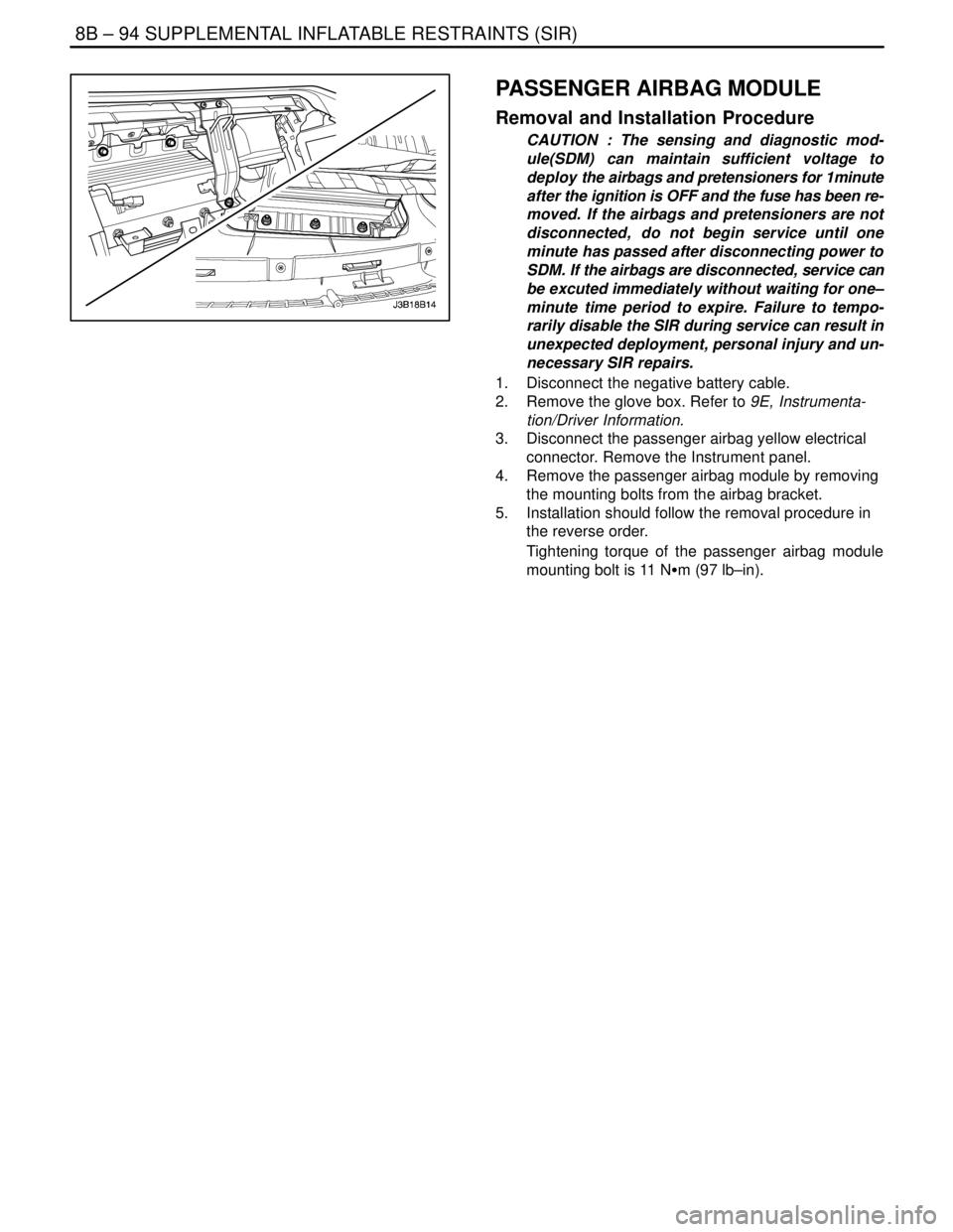
PASSENGER AIRBAG MODULE
Removal and Installation Procedure
CAUTION : The sensing and diagnostic mod-
ule(SDM) can maintain sufficient voltage to
deploy the airbags and pretensioners for 1minute
after the ignition is OFF and the fuse has been re-
moved. If the airbags and pretensioners are not
disconnected, do not begin service until one
minute has passed after disconnecting power to
SDM. If the airbags are disconnected, service can
be excuted immediately without waiting for one–
minute time period to expire. Failure to tempo-
rarily disable the SIR during service can result in
unexpected deployment, personal injury and un-
necessary SIR repairs.
1. Disconnect the negative battery cable.
2. Remove the glove box. Refer to 9E, Instrumenta-
tion/Driver Information.
3. Disconnect the passenger airbag yellow electrical
connector. Remove the Instrument panel.
4. Remove the passenger airbag module by removing
the mounting bolts from the airbag bracket.
5. Installation should follow the removal procedure in
the reverse order.
Tightening torque of the passenger airbag module
mounting bolt is 11 NSm (97 lb–in).
Page 2199 of 2643

SUPPLEMENTAL INFLATABLE RESTRAINTS (SIR) 8B – 95
DAEWOO V–121 BL4
SIDE AIRBAG SENSOR
Removal and Installation Procedure
CAUTION : The sensing and diagnostic mod-
ule(SDM) can maintain sufficient voltage to
deploy the airbags and pretensioners for 1minute
after the ignition is OFF and the fuse has been re-
moved. If the airbags and pretensioners are not
disconnected, do not begin service until one
minute has passed after disconnecting power to
SDM. If the airbags are disconnected, service can
be executed immediately without waiting for
one–minute time period to expire. Failure to tem-
porarily disable the SIR during service can result
in unexpected deployment, personal injury and
unnecessary SIR repairs.
1. Disconnect the negative battery cable.
2. Remove the trim from B pillar.
3. Remove the side airbag sensor mounting bolts.
4. Remove the side airbag sensor.
5. Installation should follow the removal procedure in
the reverse order.
Tightening torque of the side airbag sensor mounting
bolts is 8 NSm (71 lb–in).
FRONT SEAT BELT PRETENSIONER
For removal and installation, refer to Section 8A, Seat
Belts.
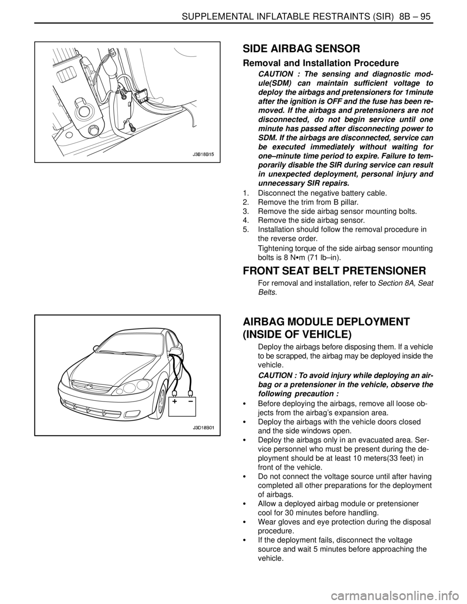
AIRBAG MODULE DEPLOYMENT
(INSIDE OF VEHICLE)
Deploy the airbags before disposing them. If a vehicle
to be scrapped, the airbag may be deployed inside the
vehicle.
CAUTION : To avoid injury while deploying an air-
bag or a pretensioner in the vehicle, observe the
following precaution :
S Before deploying the airbags, remove all loose ob-
jects from the airbag’s expansion area.
S Deploy the airbags with the vehicle doors closed
and the side windows open.
S Deploy the airbags only in an evacuated area. Ser-
vice personnel who must be present during the de-
ployment should be at least 10 meters(33 feet) in
front of the vehicle.
S Do not connect the voltage source until after having
completed all other preparations for the deployment
of airbags.
S Allow a deployed airbag module or pretensioner
cool for 30 minutes before handling.
S Wear gloves and eye protection during the disposal
procedure.
S If the deployment fails, disconnect the voltage
source and wait 5 minutes before approaching the
vehicle.
Page 2200 of 2643

8B – 96ISUPPLEMENTAL INFLATABLE RESTRAINTS (SIR)
DAEWOO V–121 BL4
Deployment Procedure
CAUTION : The sensing and diagnostic mod-
ule(SDM) can maintain sufficient voltage to
deploy the airbags and pretensioners for 1 min-
ute after the ignition is OFF and the fuse has been
removed. If the airbags and pretensioners are not
disconnected, do not begin service until one
minute has passed after disconnecting power to
SDM. If the airbags are disconnected, service can
be executed immediately without waiting for
one–minute time period to expire. Failure to tem-
porarily disable the SIR during service can result
in unexpected deployment, personal injury and
unnecessary SIR repairs.
1. Disconnect both battery cables and place the bat-
tery at least 10 meters (33 feet) from the vehicle.
2. Remove the driver side knee bolster or instrument
panel lower cover from the steering column. Refer
to Section 9G, Interior Trim.
3. At the lower steering column, cut the two wires
leading from the supplemental inflatable re-
straints(SIR) harness to the clock spring.
4. Strip 13mm(0.5 inch) of the insulation from the end
of the wires leading to the clock spring.
5. Use two additional wires, each at least 10 me-
ters(33 feet) long, to reach from the deployment
battery to the inflator module.
6. Strip 13mm(0.5 inch) of the insulation from the end
of these two additional wires.
7. Twist the two wires together at one end.
8. Place the twisted ends of the two wires near the
deployment battery. Do not connect the wires to the
battery at this time.
9. Using the free ends of the 10 meters(33 feet) wires
leading to the clock spring, make two splices, one
at each wires from the airbag modules.
10. Wrap the wires with insulation tape.
11. Now that the free ends of the 10 meters(33 feet)
wires are spliced to the airbag module wires, and
the ends that are twisted together are near the de-
ployment battery. Clear the area.
12. Untwist the wires that near the deployment battery.
13. Touch one wire to the positive battery terminal and
touch the other wire to the negative battery termi-
nal. The airbag will deploy.
14. Repeat this procedure for the passenger airbag,
side airbags and pretensioners.
15. Using proper precautions, dispose of the deployed
airbags/pretensioners. Refer to ”Deployed Airbag
Module Disposal Procedure” in this section.
Page 2207 of 2643

SECTION : 9A
BODY WIRING SYSTEM
CAUTION : Disconnect the negative battery cable before removing or installing any electrical unit or when a tool
or equipment could easily come in contact with exposed electrical terminals. Disconnecting this cable will help
prevent personal injury and damage to the vehicle. The ignition must also be in LOCK unless otherwise noted.
TABLE OF CONTENTS
SCHEMATIC AND ROUTING DIAGRAMS9A–1 . . . . .
Wire Color Chart 9A–1. . . . . . . . . . . . . . . . . . . . . . . . . . .
Power Distribution Schematic 9A–3. . . . . . . . . . . . . . .
Fuse Block Locator (Engine) 9A–12. . . . . . . . . . . . . . .
Fuse Block Locator (Passenger Compartment) 9A–12
Fuse Chart 9A–13. . . . . . . . . . . . . . . . . . . . . . . . . . . . . . Front Harness Routing 9A–15. . . . . . . . . . . . . . . . . . . .
Rear Harness Routing 9A–16. . . . . . . . . . . . . . . . . . . . .
Hatchback Rear Harness Routing 9A–17. . . . . . . . . . .
Floor Harness Routing 9A–18. . . . . . . . . . . . . . . . . . . .
Instrument Harness Routing 9A–19. . . . . . . . . . . . . . . .
Door Harness Routing 9A–20. . . . . . . . . . . . . . . . . . . . .
SCHEMATIC AND ROUTING DIAGRAMS
WIRE COLOR CHART
Wire ColorAbbreviation On Schematic
GreenDK GRN
Light GreenLT GRN
BlueDK BLU
BrownBRN
OrangeORN
YellowYEL
GreyGRY
Sky BlueLT BLU
RedRED
BlackBLK
PinkPNK
WhiteWHT
PurplePPL
Page 2208 of 2643
9A – 2IBODY WIRING SYSTEM
DAEWOO V–121 BL4
Wires With Tracers
Wire ColorAbbreviation On Schematic
Red with White TracerRED/WHT
Red with Black TracerRED/BLK
Brown with White TracerBRN/WHT
Black with White TracerBLK/WHT
Black with Yellow TracerBLK/YEL
Green with Black TracerDK GRN/BLK
Green with White TracerDK GRN/WHT
Light Green with Black TracerLT GRN/BLK
Red with Yellow TracerRED/YEL
Red with Blue TracerRED/DK BLU
Black with Brown TracerBLK/BRN
Page 2277 of 2643
9C – 4IHORN(S)
DAEWOO V–121 BL4
GENERAL DESCRIPTION
AND SYSTEM OPERATION
HORN(S)
The horns are located under the hood. They are attached
near the radiator at the front of the vehicle. The horns are
actuated by pressing the steering wheel pad, which
grounds the horns’ electrical circuit.
Page 2374 of 2643
9I – 6IWATERLEAKS
DAEWOO V–121 BL4
8. Allow the primer to dry for 5 minutes.
9. Apply the adhesive over the leak and for a distance
of 75 to 100 mm (3 to 4 inches) on both sides of the
leak.
10. Immediately after applying the adhesive, use a flat
stick or a similar tool to work the adhesive into the
leak area and into the joint between the original ma-
terial and the vehicle body in order to ensure a wa-
tertight seal.
11. Spray warm or hot water over the repaired area in
order to determine if the leak was repaired. Do not
run a heavy stream of water directly on the freshly
applied adhesive.
12. Install the trim strip lace if it was removed.
13. Install the garnish molding if it was removed.
14. Install the reveal molding.
Important : After the completion of any waterleak repair,
retest the area using the watertest stands. Do not use
localized testing procedures on the newly–repaired areas,
as the repair material may dislodge under abnormal pres-
sure.