Page 926 of 2643
FRONT SUSPENSION 2C – 9
DAEWOO V–121 BL4
MAINTENANCE AND REPAIR
ON–VEHICLE SERVICE
STABILIZER SHAFT AND
INSULATORS
Removal Procedure
1. Raise and suitably support the vehicle.
2. Remove the stabilizer shaft–to–stabilizer link nut.
3. Remove the crossmember. Refer to ”Crossmember
Assembly” in this section.
4. Remove the stabilizer shaft–to–crossmember
clamp bolts.
5. Remove the stabilizer shaft, the stabilizer shaft in-
sulator clamp, and the insulators from the vehicle.
Installation Procedure
1. Install the stabilizer shaft.
2. Install the stabilizer shaft insulator clamps, the sta-
bilizer shaft clamp bolt, and the insulators onto the
crossmember. Do not tighten the bolt.
Page 927 of 2643

2C – 10IFRONT SUSPENSION
DAEWOO V–121 BL4
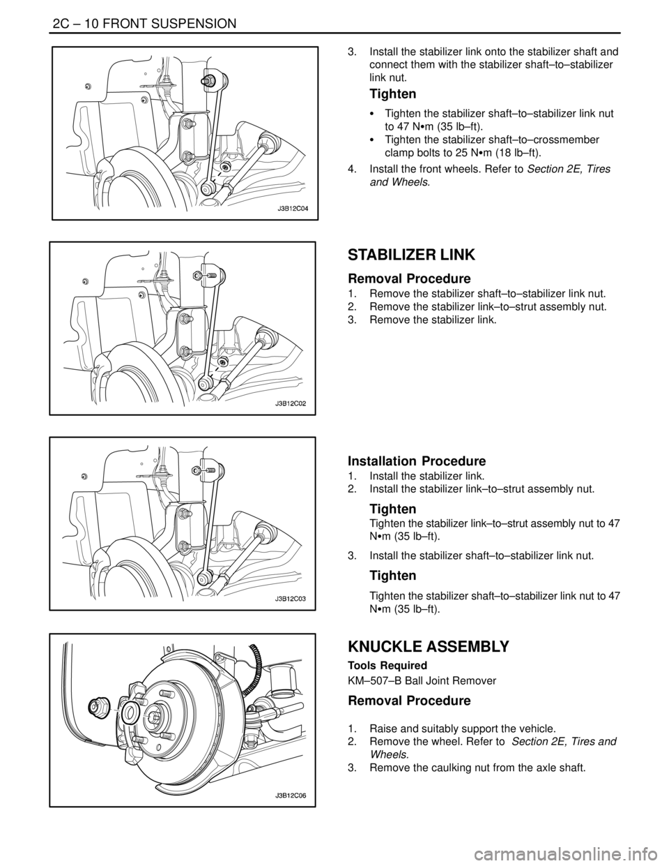
3. Install the stabilizer link onto the stabilizer shaft and
connect them with the stabilizer shaft–to–stabilizer
link nut.
Tighten
S Tighten the stabilizer shaft–to–stabilizer link nut
to 47 NSm (35 lb–ft).
S Tighten the stabilizer shaft–to–crossmember
clamp bolts to 25 NSm (18 lb–ft).
4. Install the front wheels. Refer to Section 2E, Tires
and Wheels.
STABILIZER LINK
Removal Procedure
1. Remove the stabilizer shaft–to–stabilizer link nut.
2. Remove the stabilizer link–to–strut assembly nut.
3. Remove the stabilizer link.
Installation Procedure
1. Install the stabilizer link.
2. Install the stabilizer link–to–strut assembly nut.
Tighten
Tighten the stabilizer link–to–strut assembly nut to 47
NSm (35 lb–ft).
3. Install the stabilizer shaft–to–stabilizer link nut.
Tighten
Tighten the stabilizer shaft–to–stabilizer link nut to 47
NSm (35 lb–ft).
KNUCKLE ASSEMBLY
Tools Required
KM–507–B Ball Joint Remover
Removal Procedure
1. Raise and suitably support the vehicle.
2. Remove the wheel. Refer to Section 2E, Tires and
Wheels.
3. Remove the caulking nut from the axle shaft.
Page 944 of 2643
2D – 2IREAR SUSPENSION
DAEWOO V–121 BL4
SPECIFICATIONS
FASTENER TIGHTENING SPECIFICATIONS
ApplicationNSmLb–FtLb–In
Crossmember–to–Body Bolts11 283–
Strut Dampener–to–Strut Mount Nut7555–
Rear Parallel Link–to–Crossmember Bolt9066–
Front Parallel Link–to–Knuckle Bolt12089–
Fuel Filler Hose Shield Bolt2015–
Knuckle–to–Strut Assembly Nuts10074–
Rear Parallel Link–to–Knuckle Bolt9066–
Rear Trailing Link–to–Trailing Link Bracket Nut10074–
Rear Trailing Link–to–Knuckle Nut150111–
Stabilizer Link–to–Strut Assembly Nut4735–
Stabilizer Shaft Clamp Bolts4030–
Stabilizer Shaft–to–Stabilizer Link Nut4735–
Strut Mount–to–Body Nuts3022–
Trailing Link Bracket–to–Body Bolts7052–
Trailing Link–to–Trailing Link Bracket Nut10074–
Rear Hub Assembly Bolts6548–
SPECIAL TOOLS
SPECIAL TOOLS TABLE
J–42468
Front Strut Mount
Nut WrenchKM–329–A
Spring Compressor
Page 947 of 2643
REAR SUSPENSION 2D – 5
DAEWOO V–121 BL4
1. Strut Mount Lock Nut
2. Strut Assembly–to–Body Nut
3. Strut Mount
4. Upper Spring Seat
5. Rear Spring
6. Strut Dampener Dust Cover
7. Hollow Bumper
8. Lower Spring Insulation Ring
9. Rear Strut Dampener
10. Strut Assembly–to–Knuckle Bolt
11. Strut Assembly–to–Knuckle Nut
12. Spindle Assembly
13. Brake Disc
14. Stabilizer Shaft Clamp Bolt
15. Stabilizer Shaft Clamp16. Stabilizer Shaft Insulator
17. Stabilizer Shaft
18. Stabilizer Shaft–to–Stabilizer Link Nut
19. Stabilizer Link
20. Rear Parallel Link–to–Knuckle Bolt
21. Rear Parallel Link
22. Trailing Link
23. Front Parallel Link
24. Trailing Link Bracket
25. Rear Crossmember–to–body Bolts
26. Rear Crossmember
27. Rear Crossmember Cover
28. Toe–in Adjustment Bolt
29. ABS Wiring Cover
30. Rear Drum
Page 955 of 2643

REAR SUSPENSION 2D – 13
DAEWOO V–121 BL4
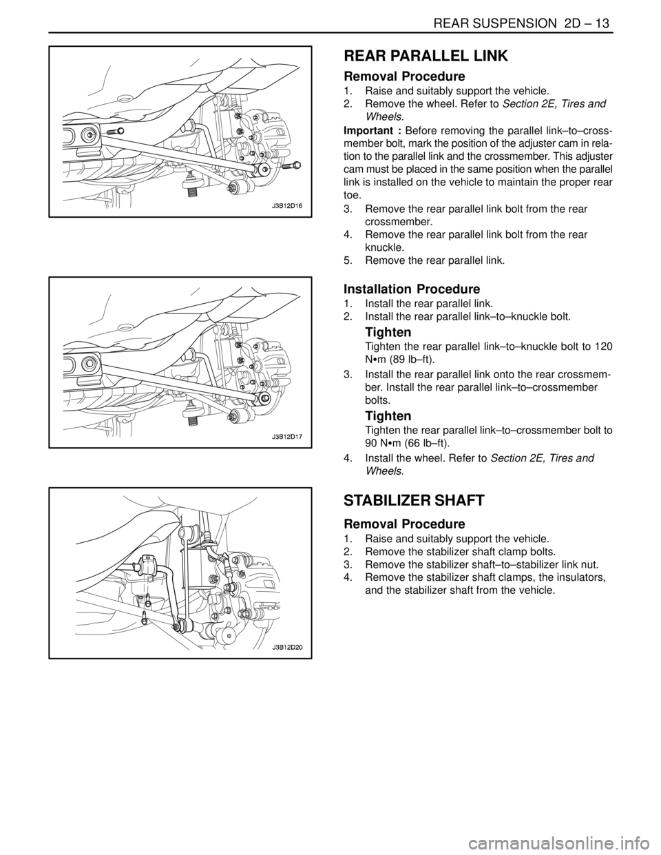
REAR PARALLEL LINK
Removal Procedure
1. Raise and suitably support the vehicle.
2. Remove the wheel. Refer to Section 2E, Tires and
Wheels.
Important : Before removing the parallel link–to–cross-
member bolt, mark the position of the adjuster cam in rela-
tion to the parallel link and the crossmember. This adjuster
cam must be placed in the same position when the parallel
link is installed on the vehicle to maintain the proper rear
toe.
3. Remove the rear parallel link bolt from the rear
crossmember.
4. Remove the rear parallel link bolt from the rear
knuckle.
5. Remove the rear parallel link.
Installation Procedure
1. Install the rear parallel link.
2. Install the rear parallel link–to–knuckle bolt.
Tighten
Tighten the rear parallel link–to–knuckle bolt to 120
NSm (89 lb–ft).
3. Install the rear parallel link onto the rear crossmem-
ber. Install the rear parallel link–to–crossmember
bolts.
Tighten
Tighten the rear parallel link–to–crossmember bolt to
90 NSm (66 lb–ft).
4. Install the wheel. Refer to Section 2E, Tires and
Wheels.
STABILIZER SHAFT
Removal Procedure
1. Raise and suitably support the vehicle.
2. Remove the stabilizer shaft clamp bolts.
3. Remove the stabilizer shaft–to–stabilizer link nut.
4. Remove the stabilizer shaft clamps, the insulators,
and the stabilizer shaft from the vehicle.
Page 956 of 2643

2D – 14IREAR SUSPENSION
DAEWOO V–121 BL4
Installation Procedure
1. Install the stabilizer shaft, the insulators, and the
stabilizer shaft clamps.
2. Install the stabilizer shaft–to–stabilizer link nut.
Tighten
Tighten the stabilizer shaft–to–stabilizer link nut to 47
NSm (35 lb–ft).
3. Install the stabilizer shaft clamp bolts.
Tighten
Tighten the stabilizer shaft clamp bolts to 40 NSm (30
lb–ft).
4. Lower the vehicle.
STABILIZER LINK
Removal Procedure
1. Raise and suitably support the vehicle.
2. Remove the wheel. Refer to Section 2E, Tires and
Wheels.
3. Remove the stabilizer shaft–to–stabilizer link nut.
4. Remove the stabilizer link–to–strut assembly nut.
5. Remove the stabilizer link.
Installation Procedure
1. Install the stabilizer link.
2. Install the stabilizer link–to–strut assembly nut.
Tighten
Tighten the stabilizer link–to–strut assembly nut to 47
NSm (35 lb–ft).
3. Install the stabilizer shaft–to–stabilizer link nut.
Tighten
Tighten the stabilizer shaft–to–stabilizer link nut to 47
NSm (35 lb–ft).
4. Install the wheel. Refer to Section 2E, Tires and
Wheels.
5. Lower the vehicle.
CROSSMEMBER
Removal Procedure
1. Raise and suitably support the vehicle.
2. Remove the front parallel link bolt from the cross-
member. Refer to ”Front Parallel Link” in this sec-
tion.
3. Remove the rear parallel link bolt from the cross-
member. Refer to ”Rear Parallel Link”in this section.
4. Remove the rear wheel speed sensor wiring from
the crossmember.
Page 991 of 2643
3A – 2IAUTOMATIC TRANSAXLE DRIVE AXLE
DAEWOO V–121 BL4
SPECIAL TOOLS
SPECIAL TOOLS TABLE
J–8059
Snap Ring Pliers
KM–507–B
Ball Joint Remover
DW340–110
Axle Shaft Remover
J–35566
Seal Clamp Pliers
COMPONENT LOCATOR
FRONT DRIVE AXLE
Page 992 of 2643
AUTOMATIC TRANSAXLE DRIVE AXLE 3A – 3
DAEWOO V–121 BL4
1. C/V Joint Assembly
2. C/V Joint
3. Seal Retaining Clamp
4. Drive Axle Outboard Seal
5. Seal Retaining Clamp
6. Axle Shaft (Left–hand Drive Shown, Right–hand
Drive Similar)7. Seal Retaining Clamp
8. Drive Axle Inboard Seal
9. Seal Retaining Clamp
10. Tripot Housing
11. Snap Ring
12. Tripot Joint Assembly