2004 DAEWOO LACETTI light
[x] Cancel search: lightPage 2013 of 2643

MANUAL CONTROL HEATING, VENTILATION AND AIR CONDITIONING SYSTEM 7B – 11
DAEWOO V–121 BL4
LEAK TESTING REFRIGERANT
SYSTEM
Test for leaks whenever you suspect a refrigerant leak in
the system. You should also test for leaks whenever you
perform a service operation which results in disturbing the
lines or the connections. Leaks are commonly found at the
refrigerant fittings or at the connections. Leaks are com-
monly caused by the following problems:
S Improper torque.
S Damaged O–ring seals.
S Dirt or lint on the O–ring seals.
Liquid Leak Detectors
Use a liquid leak detector solution on locations such as fit-
tings. Apply the solution to the area in question with the
swab that is supplied with the solution. Look for bubbles
to appear. This will indicate the existence and the location
of any leak.
For areas where this is not practical, such as sections of
the evaporator and the condenser, an electronic leak de-
tector is more useful.
Electronic Leak Detectors
Follow the manufacturer’s instructions for calibration, op-
eration, and maintenance of an electronic leak detector.
Battery condition is especially important to the accuracy
of a portable model. Set the detector to R–134a before be-
ginning the test.
Notice : Electronic leak detectors are sensitive to wind-
shield washing solutions, solvents and cleaners, and cer-
tain vehicle adhesives. Surfaces must be clean to prevent
false readings. Make sure that all surfaces are dry to pre-
vent damage to the detector.
General Testing Instructions
1. Follow the entire path of the refrigerant system.
2. Completely circle each joint at 25 to 50 mm (1 to 2
inches) per second.
3. Hold the probe tip within 6 mm (1/4 inch) of the sur-
face.4. Do not block the air intake.
5. The audible tone changes from 1 to 2 clicks per
second into a solid alarm if there is a leak. Adjust
the balance control to maintain 1 to 2 clicks per
second.
6. Test all of the following areas, even after one leak
has been confirmed:
S Evaporator inlet and outlet.
S Receiver–drier inlet and outlet.
S Condenser inlet and outlet.
S Brazed and welded areas.
S Damaged areas.
S Hose couplings.
S Compressor rear head.
S All fittings and joints.
Testing Service Ports/Access Valves
The sealing caps provide protection for the service ports.
Make sure that these caps are not missing or loose. Al-
ways use the correct cap for each port.
Testing the Evaporator Core
Leaks in the evaporator core are difficult to find. Test the
evaporator core using the following procedure:
1. Run the blower fan at the maximum speed setting
for at least 15 minutes.
2. Turn the blower OFF.
3. Wait for 10 minutes.
4. Remove the blower motor resistor. Refer to Section
7A, Heating and Ventilation System.
5. Insert the leak detector probe as close as possible
to the evaporator core. The detector will indicate a
leak with a solid alarm.
6. Use a flashlight to search for refrigerant oil on the
core surface.
Testing the Compressor Shaft Seal
1. Blow shop air behind and in front of the compressor
clutch/pulley for at least 15 seconds.
2. Wait 1 to 2 minutes.
3. Probe the area in front of the pulley. If the detector
emits a solid alarm, there is a leak.
Page 2025 of 2643

MANUAL CONTROL HEATING, VENTILATION AND AIR CONDITIONING SYSTEM 7B – 23
DAEWOO V–121 BL4
SERVICEABLE COMPONENTS
COMPONENTS USED IN NON–A/C
SYSTEMS
Refer to Section 7A, Heating and Ventilation System for
on–vehicle service procedures for the following sections:
S Blower Motor.
S Blower Resistor.
S Control Assembly Knob Lighting.
S Control Assembly.
S Heater Hoses.
S High–Blower Relay.
S A/C Control Vacuum Tank.
S Temperature Control Cable.
S Heater/Air Distributor Case Assembly (A/C Mod-
ule).
S Heater Core
Page 2028 of 2643
7B – 26IMANUAL CONTROL HEATING, VENTILATION AND AIR CONDITIONING SYSTEM
DAEWOO V–121 BL4
Installation Procedure
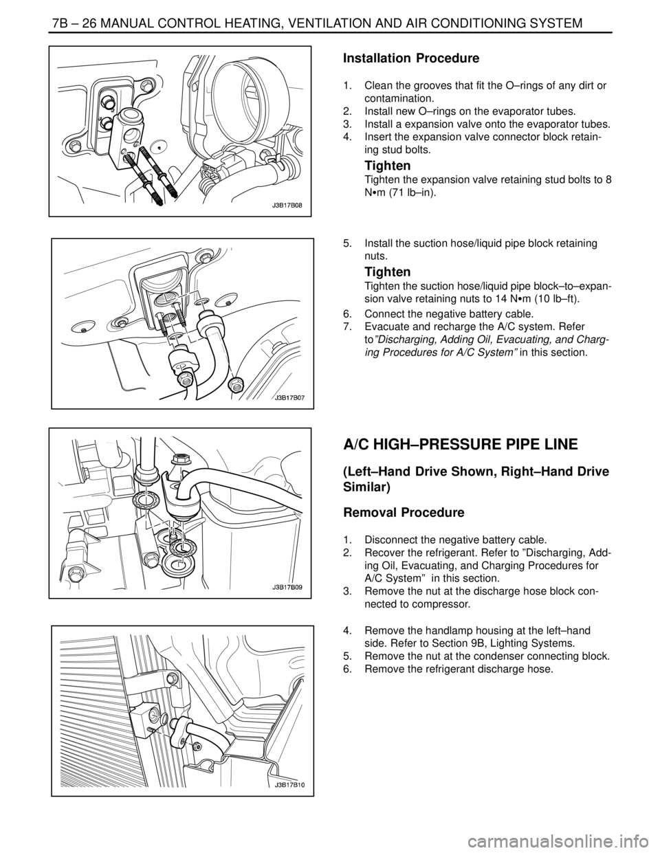
1. Clean the grooves that fit the O–rings of any dirt or
contamination.
2. Install new O–rings on the evaporator tubes.
3. Install a expansion valve onto the evaporator tubes.
4. Insert the expansion valve connector block retain-
ing stud bolts.
Tighten
Tighten the expansion valve retaining stud bolts to 8
NSm (71 lb–in).
5. Install the suction hose/liquid pipe block retaining
nuts.
Tighten
Tighten the suction hose/liquid pipe block–to–expan-
sion valve retaining nuts to 14 NSm (10 lb–ft).
6. Connect the negative battery cable.
7. Evacuate and recharge the A/C system. Refer
to”Discharging, Adding Oil, Evacuating, and Charg-
ing Procedures for A/C System” in this section.
A/C HIGH–PRESSURE PIPE LINE
(Left–Hand Drive Shown, Right–Hand Drive
Similar)
Removal Procedure
1. Disconnect the negative battery cable.
2. Recover the refrigerant. Refer to ”Discharging, Add-
ing Oil, Evacuating, and Charging Procedures for
A/C System” in this section.
3. Remove the nut at the discharge hose block con-
nected to compressor.
4. Remove the handlamp housing at the left–hand
side. Refer to Section 9B, Lighting Systems.
5. Remove the nut at the condenser connecting block.
6. Remove the refrigerant discharge hose.
Page 2029 of 2643
MANUAL CONTROL HEATING, VENTILATION AND AIR CONDITIONING SYSTEM 7B – 27
DAEWOO V–121 BL4
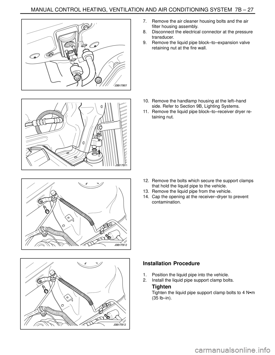
7. Remove the air cleaner housing bolts and the air
filter housing assembly.
8. Disconnect the electrical connector at the pressure
transducer.
9. Remove the liquid pipe block–to–expansion valve
retaining nut at the fire wall.
10. Remove the handlamp housing at the left–hand
side. Refer to Section 9B, Lighting Systems.
11. Remove the liquid pipe block–to–receiver dryer re-
taining nut.
12. Remove the bolts which secure the support clamps
that hold the liquid pipe to the vehicle.
13. Remove the liquid pipe from the vehicle.
14. Cap the opening at the receiver–dryer to prevent
contamination.
Installation Procedure
1. Position the liquid pipe into the vehicle.
2. Install the liquid pipe support clamp bolts.
Tighten
Tighten the liquid pipe support clamp bolts to 4 NSm
(35 lb–in).
Page 2030 of 2643
7B – 28IMANUAL CONTROL HEATING, VENTILATION AND AIR CONDITIONING SYSTEM
DAEWOO V–121 BL4
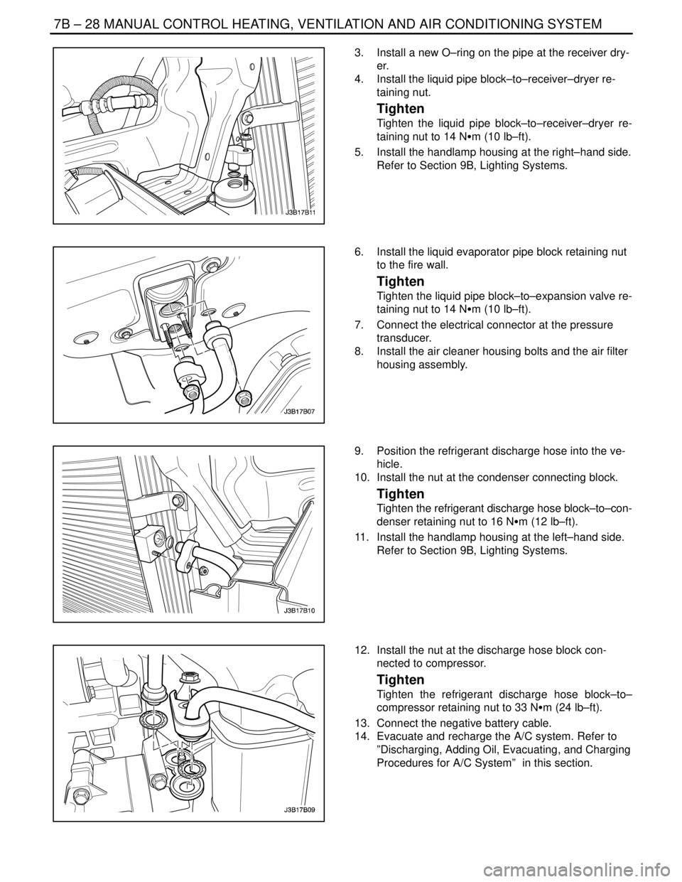
3. Install a new O–ring on the pipe at the receiver dry-
er.
4. Install the liquid pipe block–to–receiver–dryer re-
taining nut.
Tighten
Tighten the liquid pipe block–to–receiver–dryer re-
taining nut to 14 NSm (10 lb–ft).
5. Install the handlamp housing at the right–hand side.
Refer to Section 9B, Lighting Systems.
6. Install the liquid evaporator pipe block retaining nut
to the fire wall.
Tighten
Tighten the liquid pipe block–to–expansion valve re-
taining nut to 14 NSm (10 lb–ft).
7. Connect the electrical connector at the pressure
transducer.
8. Install the air cleaner housing bolts and the air filter
housing assembly.
9. Position the refrigerant discharge hose into the ve-
hicle.
10. Install the nut at the condenser connecting block.
Tighten
Tighten the refrigerant discharge hose block–to–con-
denser retaining nut to 16 NSm (12 lb–ft).
11. Install the handlamp housing at the left–hand side.
Refer to Section 9B, Lighting Systems.
12. Install the nut at the discharge hose block con-
nected to compressor.
Tighten
Tighten the refrigerant discharge hose block–to–
compressor retaining nut to 33 NSm (24 lb–ft).
13. Connect the negative battery cable.
14. Evacuate and recharge the A/C system. Refer to
”Discharging, Adding Oil, Evacuating, and Charging
Procedures for A/C System” in this section.
Page 2034 of 2643
7B – 32IMANUAL CONTROL HEATING, VENTILATION AND AIR CONDITIONING SYSTEM
DAEWOO V–121 BL4
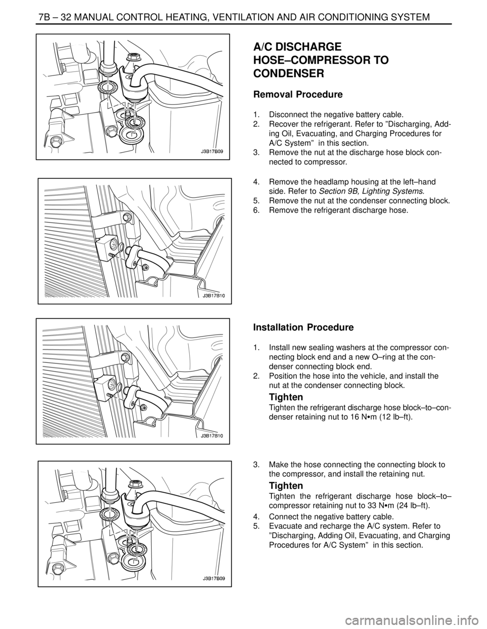
A/C DISCHARGE
HOSE–COMPRESSOR TO
CONDENSER
Removal Procedure
1. Disconnect the negative battery cable.
2. Recover the refrigerant. Refer to ”Discharging, Add-
ing Oil, Evacuating, and Charging Procedures for
A/C System” in this section.
3. Remove the nut at the discharge hose block con-
nected to compressor.
4. Remove the headlamp housing at the left–hand
side. Refer to Section 9B, Lighting Systems.
5. Remove the nut at the condenser connecting block.
6. Remove the refrigerant discharge hose.
Installation Procedure
1. Install new sealing washers at the compressor con-
necting block end and a new O–ring at the con-
denser connecting block end.
2. Position the hose into the vehicle, and install the
nut at the condenser connecting block.
Tighten
Tighten the refrigerant discharge hose block–to–con-
denser retaining nut to 16 NSm (12 lb–ft).
3. Make the hose connecting the connecting block to
the compressor, and install the retaining nut.
Tighten
Tighten the refrigerant discharge hose block–to–
compressor retaining nut to 33 NSm (24 lb–ft).
4. Connect the negative battery cable.
5. Evacuate and recharge the A/C system. Refer to
”Discharging, Adding Oil, Evacuating, and Charging
Procedures for A/C System” in this section.
Page 2040 of 2643
7B – 38IMANUAL CONTROL HEATING, VENTILATION AND AIR CONDITIONING SYSTEM
DAEWOO V–121 BL4
V5 AIR CONDITIONING COMPRESSOR OVERHAUL
CLUTCH PLATE AND HUB
ASSEMBLY
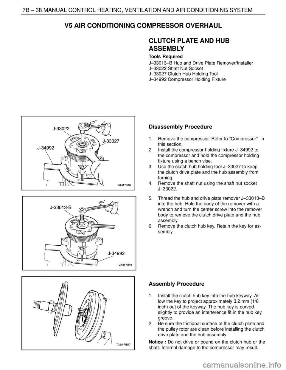
Tools Required
J–33013–B Hub and Drive Plate Remover/Installer
J–33022 Shaft Nut Socket
J–33027 Clutch Hub Holding Tool
J–34992 Compressor Holding Fixture
Disassembly Procedure
1. Remove the compressor. Refer to ”Compressor” in
this section.
2. Install the compressor holding fixture J–34992 to
the compressor and hold the compressor holding
fixture using a bench vise.
3. Use the clutch hub holding tool J–33027 to keep
the clutch drive plate and the hub assembly from
turning.
4. Remove the shaft nut using the shaft nut socket
J–33022.
5. Thread the hub and drive plate remover J–33013–B
into the hub. Hold the body of the remover with a
wrench and turn the center screw into the remover
body to remove the clutch drive plate and the hub
assembly.
6. Remove the clutch hub key. Retain the key for as-
sembly.
Assembly Procedure
1. Install the clutch hub key into the hub keyway. Al-
low the key to project approximately 3.2 mm (1/8
inch) out of the keyway. The hub key is curved
slightly to provide an interference fit in the hub key
groove.
2. Be sure the frictional surface of the clutch plate and
the pulley rotor are clean before installing the clutch
drive plate and the hub assembly.
Notice : Do not drive or pound on the clutch hub or the
shaft. Internal damage to the compressor may result.
Page 2041 of 2643
MANUAL CONTROL HEATING, VENTILATION AND AIR CONDITIONING SYSTEM 7B – 39
DAEWOO V–121 BL4
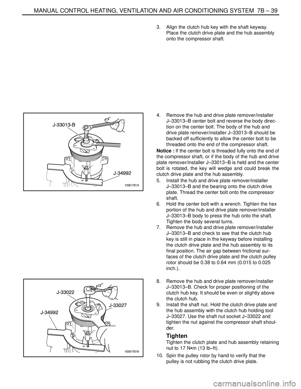
3. Align the clutch hub key with the shaft keyway.
Place the clutch drive plate and the hub assembly
onto the compressor shaft.
4. Remove the hub and drive plate remover/installer
J–33013–B center bolt and reverse the body direc-
tion on the center bolt. The body of the hub and
drive plate remover/installer J–33013–B should be
backed off sufficiently to allow the center bolt to be
threaded onto the end of the compressor shaft.
Notice : If the center bolt is threaded fully onto the end of
the compressor shaft, or if the body of the hub and drive
plate remover/installer J–33013–B is held and the center
bolt is rotated, the key will wedge and could break the
clutch drive plate and the hub assembly.
5. Install the hub and drive plate remover/installer
J–33013–B and the bearing onto the clutch drive
plate. Thread the center bolt onto the compressor
shaft.
6. Hold the center bolt with a wrench. Tighten the hex
portion of the hub and drive plate remover/installer
J–33013–B body to press the hub onto the shaft.
Tighten the body several turns.
7. Remove the hub and drive plate remover/installer
J–33013–B and check to see that the clutch hub
key is still in place in the keyway before installing
the clutch drive plate and the hub assembly to its
final position. The air gap between frictional sur-
faces of the clutch drive plate and the clutch pulley
rotor should be 0.38 to 0.64 mm (0.015 to 0.025
inch.).
8. Remove the hub and drive plate remover/installer
J–33013–B. Check for proper positioning of the
clutch hub key. It should be even or slightly above
the clutch hub.
9. Install the shaft nut. Hold the clutch drive plate and
the hub assembly with the clutch hub holding tool
J–33027. Use the shaft nut socket J–33022 and
tighten the nut against the compressor shaft shoul-
der.
Tighten
Tighten the clutch plate and hub assembly retaining
nut to 17 NSm (13 lb–ft).
10. Spin the pulley rotor by hand to verify that the
pulley is not rubbing the clutch drive plate.