2004 DAEWOO LACETTI engine controls
[x] Cancel search: engine controlsPage 5 of 2643

v
TABLE OF CONTENTS
Section 0B General Information
Section 1 Engine
Section 1A General Engine Information
Section 1C1 1.4L/1.6L DOHC Engine Mechanical
Section 1C2 1.8L DOHC Engine Mechanical
Section 1D Engine Cooling
Section 1E Engine Electrical
Section 1F Engine Controls
Section 1G Engine Exhaust
Section 2 Suspension
Section 2A Suspension Diagnosis
Section 2B Wheel Alignment
Section 2C Front Suspension
Section 2D Rear Suspension
Section 2E Tires and Wheels
Section 3 Driveline/Axle
Section 3A Automatic Transaxle Drive Axle
Section 3B Manual Transaxle Drive Axle
Section 4 Brakes
Section 4A Hydraulic Brakes
Section 4B Master Cylinder
Section 4C Power Booster
Section 4D Front Disc Brakes
Section 4E1 Rear Disc Brakes
Section 4E2 Rear Drum Brakes
Section 4F Antilock Brake System
Section 4G Parking Brake
Section 5 Transmission/Transaxle
Section 5A1 ZF 4HP16 Automatic Transaxle
Section 5A2 AISIN Automatic Transaxle
Section 5B Five-Speed Manual Transaxle
Section 5C Clutch
Section 6 Steering
Section 6A Power Steering System
Section 6B Power Steering PumpSection 6C Power Steering Gear
Section 6E Steering Wheel and Column
Section 7 Heating, Ventilation, and Air
Conditioning (HVAC)
Section 7A Heating and Ventilation System
Section 7B Manual Control Heating, Ventilation,
and Air Conditioning System
Section 7D Automatic Temperature Control HVAC
Section 8 Restraints
Section 8A Seat Belts
Section 8B Supplemental Inflatable Restraints
(SIR)
Section 9 Body and Accessories
Section 9A Body Wiring System
Section 9B Lighting Systems
Section 9C Horns
Section 9D Wipers/Washer Systems
Section 9E Instrumentation/Driver Information
Section 9F Audio Systems
Section 9G Interior Trim
Section 9H Seats
Section 9I Waterleaks
Section 9J Windnoise
Section 9K Squeaks and Rattles
Section 9L Glass and Mirrors
Section 9M Exterior Trim
Section 9N Frame and Underbody
Section 9O Bumpers and Fascias
Section 9P Doors
Section 9Q Roof
Section 9R Body Front End
Section 9S Body Rear End
Section 9T1 Remote Keyless Entry and Anti–Theft
System
Section 9T2 Immobilizer Anti–Theft System
Page 136 of 2643
1C2 – 16I1.8L DOHC ENGINE MECHANICAL
DAEWOO V–121 BL4
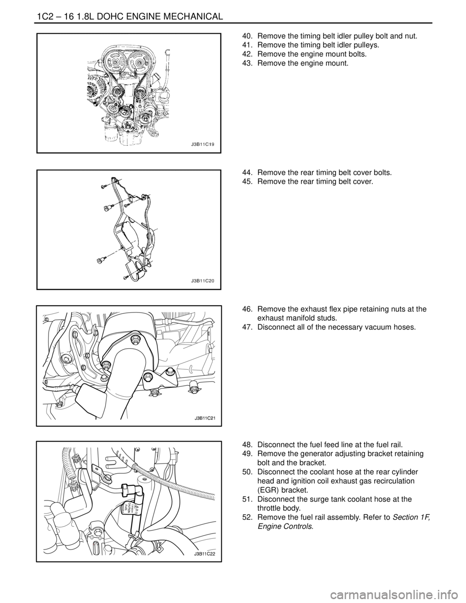
40. Remove the timing belt idler pulley bolt and nut.
41. Remove the timing belt idler pulleys.
42. Remove the engine mount bolts.
43. Remove the engine mount.
44. Remove the rear timing belt cover bolts.
45. Remove the rear timing belt cover.
46. Remove the exhaust flex pipe retaining nuts at the
exhaust manifold studs.
47. Disconnect all of the necessary vacuum hoses.
48. Disconnect the fuel feed line at the fuel rail.
49. Remove the generator adjusting bracket retaining
bolt and the bracket.
50. Disconnect the coolant hose at the rear cylinder
head and ignition coil exhaust gas recirculation
(EGR) bracket.
51. Disconnect the surge tank coolant hose at the
throttle body.
52. Remove the fuel rail assembly. Refer to Section 1F,
Engine Controls.
Page 138 of 2643
1C2 – 18I1.8L DOHC ENGINE MECHANICAL
DAEWOO V–121 BL4
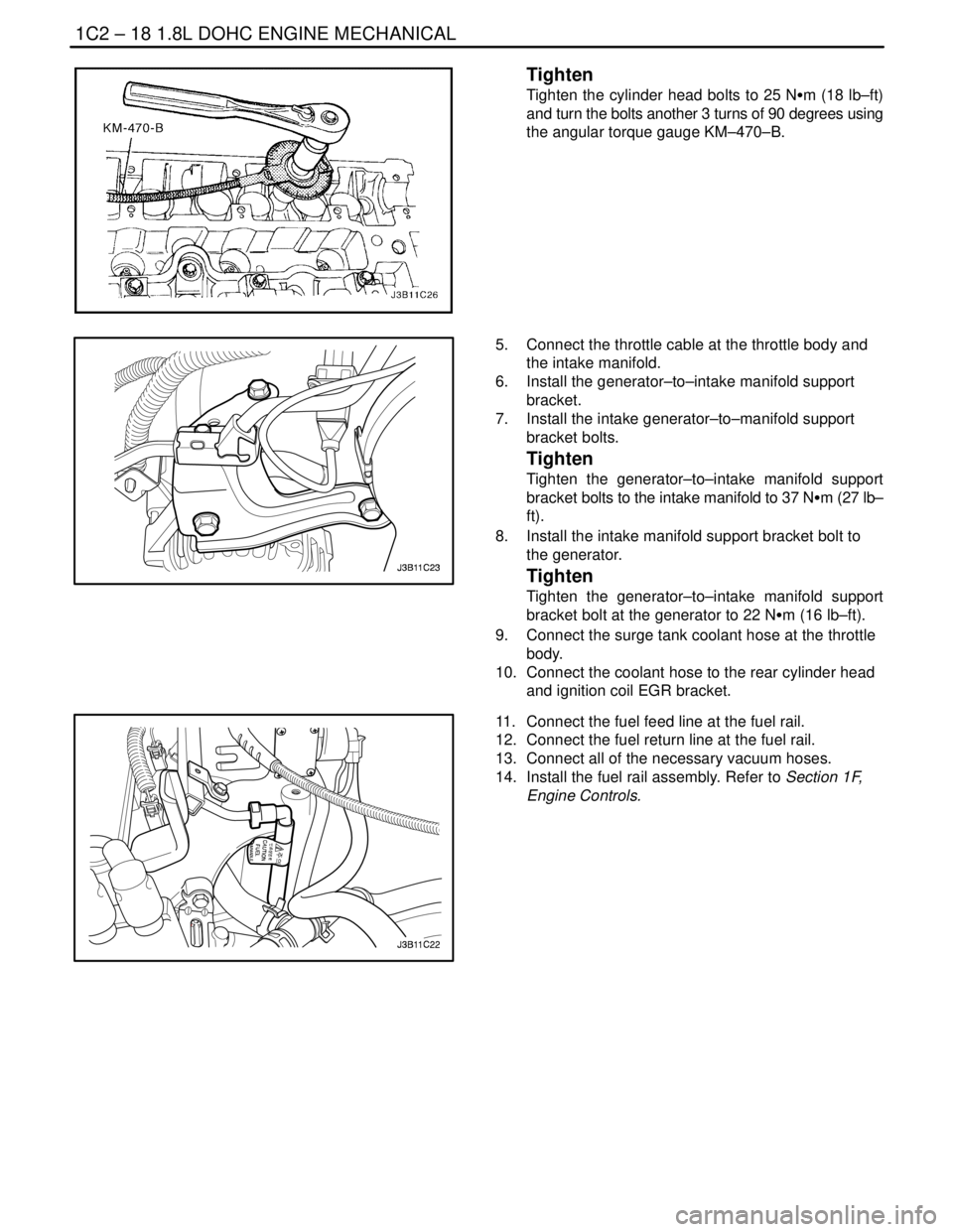
Tighten
Tighten the cylinder head bolts to 25 NSm (18 lb–ft)
and turn the bolts another 3 turns of 90 degrees using
the angular torque gauge KM–470–B.
5. Connect the throttle cable at the throttle body and
the intake manifold.
6. Install the generator–to–intake manifold support
bracket.
7. Install the intake generator–to–manifold support
bracket bolts.
Tighten
Tighten the generator–to–intake manifold support
bracket bolts to the intake manifold to 37 NSm (27 lb–
ft).
8. Install the intake manifold support bracket bolt to
the generator.
Tighten
Tighten the generator–to–intake manifold support
bracket bolt at the generator to 22 NSm (16 lb–ft).
9. Connect the surge tank coolant hose at the throttle
body.
10. Connect the coolant hose to the rear cylinder head
and ignition coil EGR bracket.
11. Connect the fuel feed line at the fuel rail.
12. Connect the fuel return line at the fuel rail.
13. Connect all of the necessary vacuum hoses.
14. Install the fuel rail assembly. Refer to Section 1F,
Engine Controls.
Page 159 of 2643
1.8L DOHC ENGINE MECHANICAL 1C2 – 39
DAEWOO V–121 BL4
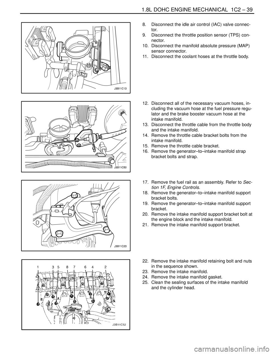
8. Disconnect the idle air control (IAC) valve connec-
tor.
9. Disconnect the throttle position sensor (TPS) con-
nector.
10. Disconnect the manifold absolute pressure (MAP)
sensor connector.
11. Disconnect the coolant hoses at the throttle body.
12. Disconnect all of the necessary vacuum hoses, in-
cluding the vacuum hose at the fuel pressure regu-
lator and the brake booster vacuum hose at the
intake manifold.
13. Disconnect the throttle cable from the throttle body
and the intake manifold.
14. Remove the throttle cable bracket bolts from the
intake manifold.
15. Remove the throttle cable bracket.
16. Remove the generator–to–intake manifold strap
bracket bolts and strap.
17. Remove the fuel rail as an assembly. Refer to Sec-
tion 1F, Engine Controls.
18. Remove the generator–to–intake manifold support
bracket bolts.
19. Remove the generator–to–intake manifold support
bracket.
20. Remove the intake manifold support bracket bolt at
the engine block and the intake manifold.
21. Remove the intake manifold support bracket.
22. Remove the intake manifold retaining bolt and nuts
in the sequence shown.
23. Remove the intake manifold.
24. Remove the intake manifold gasket.
25. Clean the sealing surfaces of the intake manifold
and the cylinder head.
Page 160 of 2643
1C2 – 40I1.8L DOHC ENGINE MECHANICAL
DAEWOO V–121 BL4
Installation Procedure
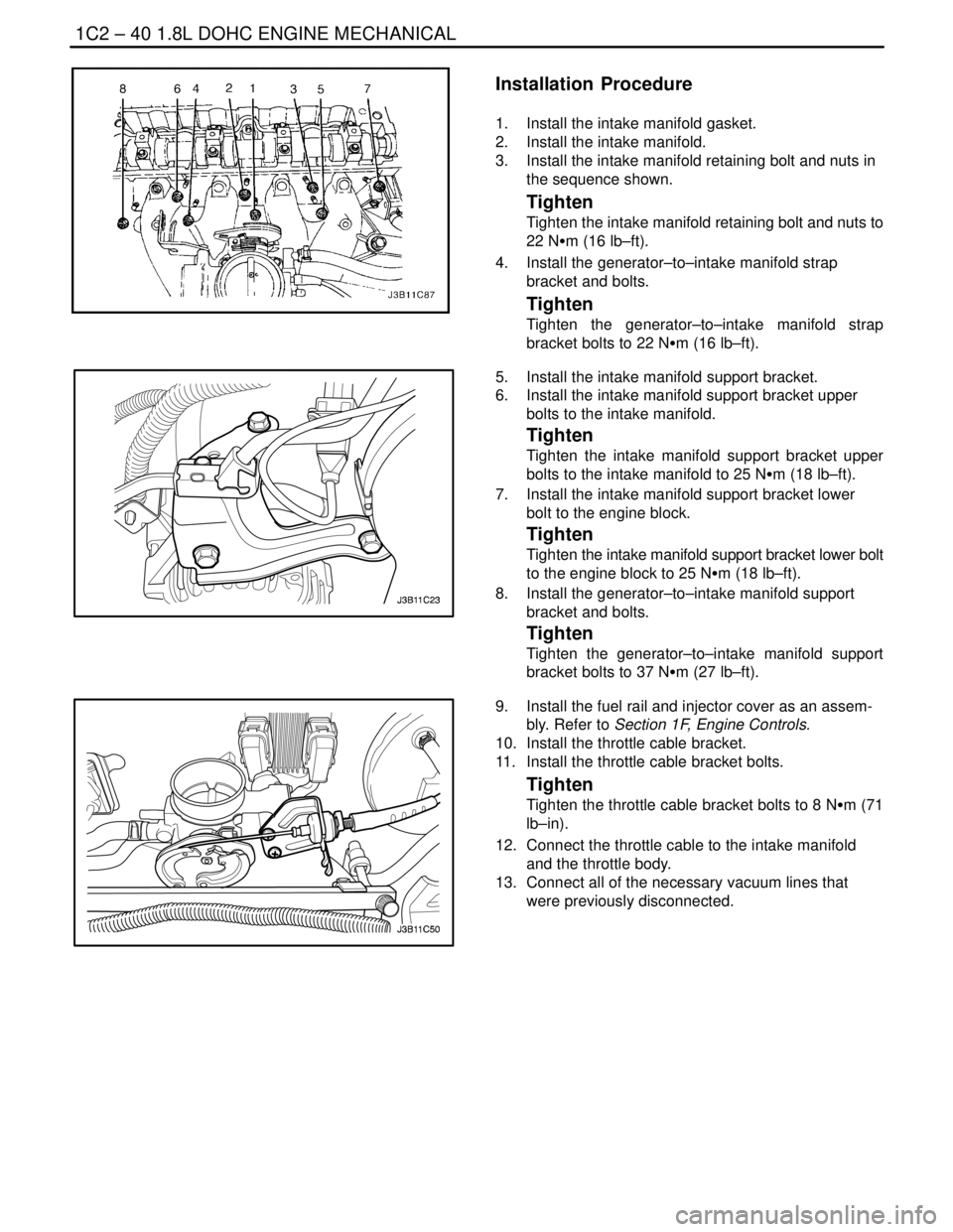
1. Install the intake manifold gasket.
2. Install the intake manifold.
3. Install the intake manifold retaining bolt and nuts in
the sequence shown.
Tighten
Tighten the intake manifold retaining bolt and nuts to
22 NSm (16 lb–ft).
4. Install the generator–to–intake manifold strap
bracket and bolts.
Tighten
Tighten the generator–to–intake manifold strap
bracket bolts to 22 NSm (16 lb–ft).
5. Install the intake manifold support bracket.
6. Install the intake manifold support bracket upper
bolts to the intake manifold.
Tighten
Tighten the intake manifold support bracket upper
bolts to the intake manifold to 25 NSm (18 lb–ft).
7. Install the intake manifold support bracket lower
bolt to the engine block.
Tighten
Tighten the intake manifold support bracket lower bolt
to the engine block to 25 NSm (18 lb–ft).
8. Install the generator–to–intake manifold support
bracket and bolts.
Tighten
Tighten the generator–to–intake manifold support
bracket bolts to 37 NSm (27 lb–ft).
9. Install the fuel rail and injector cover as an assem-
bly. Refer to Section 1F, Engine Controls.
10. Install the throttle cable bracket.
11. Install the throttle cable bracket bolts.
Tighten
Tighten the throttle cable bracket bolts to 8 NSm (71
lb–in).
12. Connect the throttle cable to the intake manifold
and the throttle body.
13. Connect all of the necessary vacuum lines that
were previously disconnected.
Page 167 of 2643

1.8L DOHC ENGINE MECHANICAL 1C2 – 47
DAEWOO V–121 BL4
19. Disconnect the oxygen (O2) sensor connector, if
equipped.
20. Disconnect the idle air control (IAC) valve connec-
tor.
21. Disconnect the throttle position sensor (TPS) con-
nector.
22. Disconnect the engine coolant temperature sensor
(CTS) connector.
23. Disconnect the CTS connector.
24. Disconnect the generator voltage regulator connec-
tor and power lead.
25. Disconnect all of the necessary vacuum lines, in-
cluding the brake booster vacuum hose.
26. Disconnect the fuel return line at the fuel rail.
27. Disconnect the fuel feed line at the fuel rail.
28. Remove the fuel rail and injector channel cover as
an assembly. Refer to Section 1F, Engine Controls.
29. Disconnect the throttle cable from the throttle body
and the intake manifold bracket.
30. Disconnect the coolant hose at the throttle body.
31. Disconnect the heater outlet hose at the coolant
pipe.
32. Disconnect the coolant bypass hose from the cylin-
der head.
33. Disconnect the surge tank coolant hose from the
coolant pipe.
34. Disconnect the lower radiator hose from the coolant
pipe.
35. Disconnect the starter solenoid ”S” terminal wire
and power lead.
36. Remove the A/C compressor. Refer to Section 7B,
Manual Control Heating, Ventilation, and Air Condi-
tioning Systems.
37. Remove the exhaust flex pipe retaining nuts from
the exhaust manifold studs.
38. Remove the exhaust flex pipe retaining nuts from
the catalytic converter or the connecting pipe.
39. Remove the exhaust flex pipe.
Page 170 of 2643
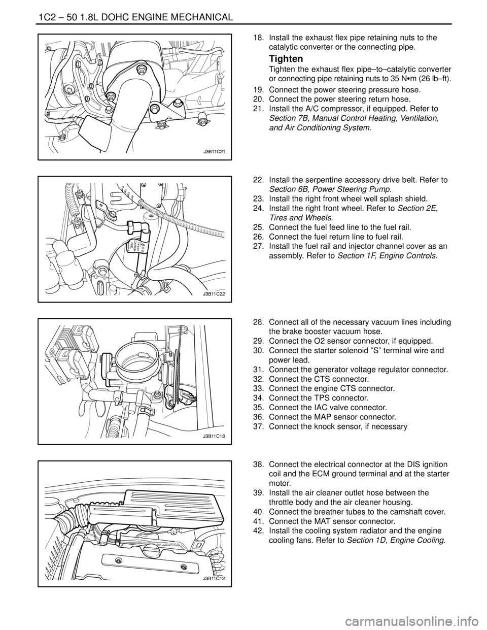
1C2 – 50I1.8L DOHC ENGINE MECHANICAL
DAEWOO V–121 BL4
18. Install the exhaust flex pipe retaining nuts to the
catalytic converter or the connecting pipe.
Tighten
Tighten the exhaust flex pipe–to–catalytic converter
or connecting pipe retaining nuts to 35 NSm (26 lb–ft).
19. Connect the power steering pressure hose.
20. Connect the power steering return hose.
21. Install the A/C compressor, if equipped. Refer to
Section 7B, Manual Control Heating, Ventilation,
and Air Conditioning System.
22. Install the serpentine accessory drive belt. Refer to
Section 6B, Power Steering Pump.
23. Install the right front wheel well splash shield.
24. Install the right front wheel. Refer to Section 2E,
Tires and Wheels.
25. Connect the fuel feed line to the fuel rail.
26. Connect the fuel return line to fuel rail.
27. Install the fuel rail and injector channel cover as an
assembly. Refer to Section 1F, Engine Controls.
28. Connect all of the necessary vacuum lines including
the brake booster vacuum hose.
29. Connect the O2 sensor connector, if equipped.
30. Connect the starter solenoid ”S” terminal wire and
power lead.
31. Connect the generator voltage regulator connector.
32. Connect the CTS connector.
33. Connect the engine CTS connector.
34. Connect the TPS connector.
35. Connect the IAC valve connector.
36. Connect the MAP sensor connector.
37. Connect the knock sensor, if necessary
38. Connect the electrical connector at the DIS ignition
coil and the ECM ground terminal and at the starter
motor.
39. Install the air cleaner outlet hose between the
throttle body and the air cleaner housing.
40. Connect the breather tubes to the camshaft cover.
41. Connect the MAT sensor connector.
42. Install the cooling system radiator and the engine
cooling fans. Refer to Section 1D, Engine Cooling.
Page 176 of 2643
1C2 – 56I1.8L DOHC ENGINE MECHANICAL
DAEWOO V–121 BL4
UNIT REPAIR
CYLINDER HEAD AND VALVE TRAIN
COMPONENTS
Tools Required
MKM–571–B Gauge
KM–340–0 Cutter Set
KM–340–7 Guide Drift
KM–340–13 Cutters
KM–340–26 Cutters
KM–348 Valve Spring Compressor
KM–653 Adapter
KM–805 Valve Guide Reamer
Disassembly Procedure
1. Remove the cylinder head with the intake manifold
and the exhaust manifold attached. Refer to ”Cylin-
der Head and Gasket” in this section.
2. Remove the exhaust manifold heat shield bolts.
3. Remove the exhaust manifold heat shield.
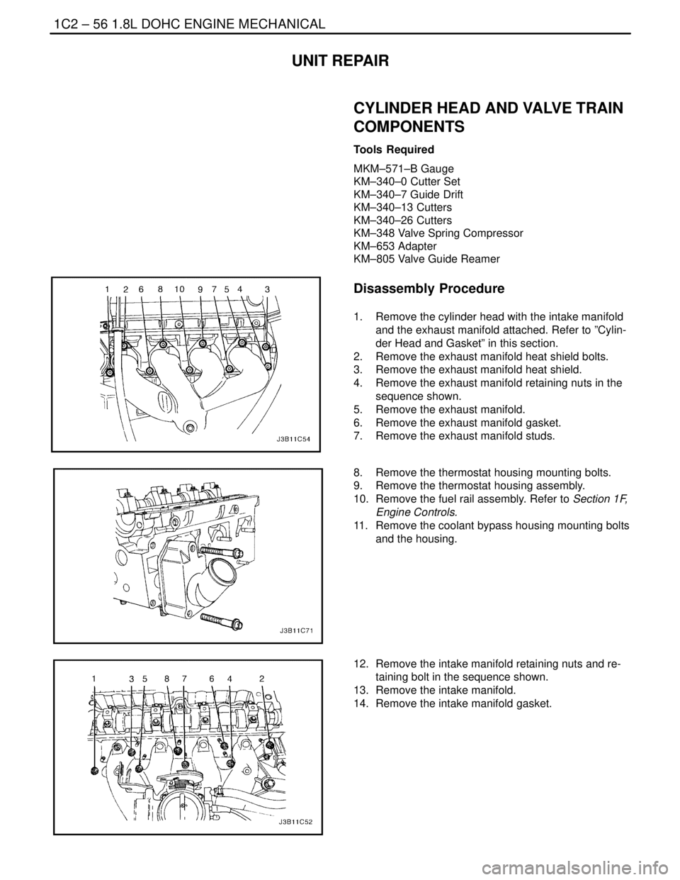
4. Remove the exhaust manifold retaining nuts in the
sequence shown.
5. Remove the exhaust manifold.
6. Remove the exhaust manifold gasket.
7. Remove the exhaust manifold studs.
8. Remove the thermostat housing mounting bolts.
9. Remove the thermostat housing assembly.
10. Remove the fuel rail assembly. Refer to Section 1F,
Engine Controls.
11. Remove the coolant bypass housing mounting bolts
and the housing.
12. Remove the intake manifold retaining nuts and re-
taining bolt in the sequence shown.
13. Remove the intake manifold.
14. Remove the intake manifold gasket.