2004 DAEWOO LACETTI light
[x] Cancel search: lightPage 1829 of 2643

FIVE–SPEED MANUAL TRANSAXLE 5B – 5
DAEWOO V–121 BL4
DIAGNOSIS
ISOLATE NOISE
Identify the cause of any noise before attempting to repair
the clutch, the transaxle, or their related link–ages.
Symptoms of trouble with the clutch or the manual trans-
axle include:
S A great effort required to shift gears.
S The sound of gears clashing and grinding.
S Gear blockout.
Any of these conditions requires a careful analysis. Make
the following checks before disassembling the clutch or
the transaxle for repairs.
Road Travel Noise
Many noises that appear to come from the transaxle may
actually originate with other sources such as the:
S Tires.
S Road surfaces.
S Wheel bearings.
S Engine.
S Exhaust system.
These noises may vary according to the:
S Size of the vehicle.
S Type of the vehicle.
S Amount of insulation used in the body of the ve-
hicle.
Transaxle Noise
Transaxle gears, like any mechanical device, are not ab-
solutely quiet and will make some noise during normal op-
eration.
To verify suspected transaxle noises:
1. Select a smooth, level asphalt road to reduce tire
and resonant body noise.
2. Drive the vehicle far enough to warm up all the lu-
bricants thoroughly.
3. Record the speed and the gear range of the trans-
axle when the noise occurs.
4. Check for noises with the vehicle stopped, but with
the engine running.
5. Determine if the noise occurs while the vehicle op-
erates in:
S Drive – under a light acceleration or a heavy
pull.
S Float – maintaining a constant speed with a light
throttle on a level road.
S Coast – with the transaxle in gear and the
throttle partly or fully closed.
S All of the above.
Bearing Noise
Differential Side Bearing Noise
Differential side bearing noise and wheel bearing noise
can be confused easily. Since side bearings are pre–
loaded, a differential side bearing noise should not dimin-
ish much when the differential/transaxle is run with the
wheels off the ground.
Wheel Bearing Noise
Wheel bearings produce a rough growl or grating sound
that will continue when the vehicle is coasting and the
transaxle is in NEUTRAL. Since wheel bearings are not
pre–loaded, a wheel bearing noise should diminish con-
siderably when the wheels are off the ground.
Other Noise
Brinelling
A brinelled bearing causes a ”knock” or ”click” approxi-
mately every second revolution of the wheel because the
bearing rollers do not travel at the same speed as the
wheel. In operation, the effect is characterized by a low–
pitched noise.
A brinelled bearing is caused by excessive thrust which
pushes the balls up on the pathway and creates a triangu-
lar–shaped spot in the bearing race. A brinelled bearing
can also be caused from pressing one race into position
by applying pressure on the other race.
A false indication of a brinelled bearing occurs as a result
of vibration near the area where the bearing is mounted.
Brinelling is identified by slight indentations, resulting in a
washboard effect in the bearing race.
Lapping
Lapped bearing noise occurs when fine particles of abra-
sive materials such as scale, sand, or emery circulate
through the oil in the vehicle, causing the surfaces of the
roller and the race to wear away. Bearings that wear loose
but remain smooth, without spalling or pitting, are the re-
sult of dirty oil.
Locking
Large particles of foreign material wedged between the
roller and the race usually causes one of the races to turn,
creating noise from a locked bearing. Pre–loading regular
taper roller bearings to a value higher than that specified
also can result in locked bearings
Pitting
Pitting on the rolling surface comes from normal wear and
the introduction of foreign materials.
Spalling
Spalled bearings have flaked or pitted rollers or races
caused by an overload or an incorrect assembly that re-
sults in a misalignment, a cocking of bearings, or adjust-
ments that are too tight.
After completing these checks, refer to the ”Diagnosis
Chart” in this section.
Page 1894 of 2643

CLUTCH 5C – 7
DAEWOO V–121 BL4
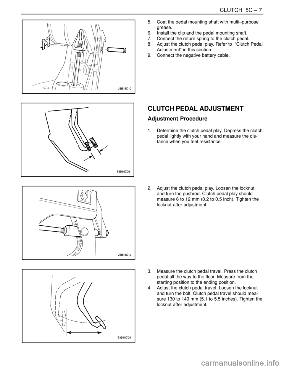
5. Coat the pedal mounting shaft with multi–purpose
grease.
6. Install the clip and the pedal mounting shaft.
7. Connect the return spring to the clutch pedal.
8. Adjust the clutch pedal play. Refer to ”Clutch Pedal
Adjustment” in this section.
9. Connect the negative battery cable.
CLUTCH PEDAL ADJUSTMENT
Adjustment Procedure
1. Determine the clutch pedal play. Depress the clutch
pedal lightly with your hand and measure the dis-
tance when you feel resistance.
2. Adjust the clutch pedal play. Loosen the locknut
and turn the pushrod. Clutch pedal play should
measure 6 to 12 mm (0.2 to 0.5 inch). Tighten the
locknut after adjustment.
3. Measure the clutch pedal travel. Press the clutch
pedal all the way to the floor. Measure from the
starting position to the ending position.
4. Adjust the clutch pedal travel. Loosen the locknut
and turn the bolt. Clutch pedal travel should mea-
sure 130 to 140 mm (5.1 to 5.5 inches). Tighten the
locknut after adjustment.
Page 1924 of 2643

POWER STEERING GEAR 6C – 7
DAEWOO V–121 BL4
SPEED SENSITIVE POWER STEERING SYSTEM
OPERATING WITH FULL ASSIST AT ALL TIMES
StepActionValue(s)YesNo
1Perform an initial inspection of the power steering
system.
Is the system operational?–Go to Step 2Go to
Section 6A,
Power Steering
System
2Check the speedometer.
Is the speedometer inoperative?–Go to
Section5,
TransaxleGo to Step 3
3Check the diagnostic trouble codes at the engine
control module (ECM).
Is the ECM code 24 set?–Go to
Section1F,
Engine
ControlsGo to Step 4
41. Turn the ignition ON.
2. Disconnect the electronic variable orifice (EVO)
solenoid actuator electrical connector at the
power steering pump.
3. Probe terminal 1 of the EVO actuator connec-
tor with a voltmeter.
Does the voltmeter display the specified value?–Go to Step 6Go to Step 5
5Repair the open or short in the circuit between termi-
nal 1 of the EVO solenoid actuator electrical connec-
tor and terminal 2 on the speed sensitive power
steering (SSPS) control module connector.
Is the repair complete?–System OK–
61. Remove the EVO solenoid actuator from the
power steering pump.
2. Turn the actuator upside down to position the
pintle.
3. Stimulate the actuator by connecting it to the
battery.
Does the actuator click?–Go to Step 8Go to Step 7
7Replace the EVO solenoid actuator.
Is the repair complete?–System OK–
81. Turn the ignition OFF.
2. Remove the SSPS control module from the
control module bracket.
3. Disconnect the SSPS control module connec-
tor.
4. Connect a test light from terminal 8 on the
SSPS control module connector to the ground.
5. Turn the ignition ON.
Is the test light on?–Go to Step 14Go to Step 9
9Check the ignition fuse.
Is the ignition fuse open?–Go to Step 10Go to Step 11
10Replace the ignition fuse.
Is the repair complete?–System OK–
11Check for an open or short in the circuit between ter-
minal 8 of the control module connector and the I/P
fuse block.
Is the connection faulty?–Go to Step 12Go to Step 13
Page 1925 of 2643

6C – 8IPOWER STEERING GEAR
DAEWOO V–121 BL4
StepNo Yes Value(s) Action
12Repair the open or short in the circuit between termi-
nal 8 of the SSPS control module connector and the
I/P fuse block.
Is the repair complete?–System OK–
13Repair the power feed to the ignition fuse F2.
Is the repair complete?–System OK–
141. Turn the ignition OFF.
2. Connect a test light from terminal 10 of the
SSPS control module connector to B+.
Is the test light on?–Go to Step 16Go to Step 15
15Repair the open in the ground circuit between termi-
nal 10 of the SSPS control module connector and
G203.
Is the repair complete?–System OK–
16Check for a short to B+ or an open in the circuit be-
tween terminal 1 of the SSPS control module con-
nector and terminal B of the EVO solenoid actuator
connector.
Is the connection faulty?–Go to Step 17Go to Step 18
17Repair the short to B+ or an open in the circuit be-
tween terminal 1 of the SSPS control module con-
nector and terminal 2 of the EVO solenoid actuator
connector.
Is the repair complete?–System OK–
181. Disconnect the steering wheel rotation sensor.
2. Turn the ignition ON.
3. Check for an open, short to ground, short to
B+, or poor terminal contact between terminal
5 of the SSPS control module connector and
terminal 1 of the steering wheel rotation sensor
connector.
Is the connection faulty?–Go to Step 19Go to Step 20
19Repair the open, short to ground, short to B+, or poor
terminal contact between terminal 5 of the SSPS
control module connector and terminal 1 of the
steering wheel rotation sensor connector.
Is the repair complete?–System OK–
20Check for an open between terminal 3 of the SSPS
control module connector and terminal 3 of the
steering wheel rotation sensor connector.
Is the connection faulty?–Go to Step 21Go to Step 22
21Repair the open between terminal 3 of the SSPS
control module connector and terminal 3 of the
steering wheel rotation sensor connector.
Is the repair complete?–System OK–
22Check for an open, short to ground, short to B+, or
poor terminal contact between terminal 14 of the
SSPS control module connector and terminal 2 of
the steering wheel rotation sensor connector.
Is the connection faulty?–Go to Step 23Go to Step 24
Page 1936 of 2643

POWER STEERING GEAR 6C – 19
DAEWOO V–121 BL4
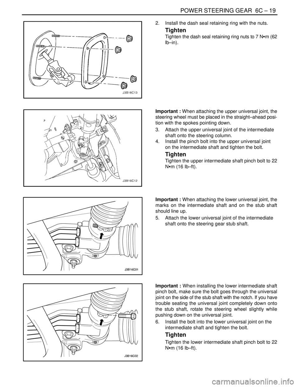
2. Install the dash seal retaining ring with the nuts.
Tighten
Tighten the dash seal retaining ring nuts to 7 NSm (62
lb–in).
Important : When attaching the upper universal joint, the
steering wheel must be placed in the straight–ahead posi-
tion with the spokes pointing down.
3. Attach the upper universal joint of the intermediate
shaft onto the steering column.
4. Install the pinch bolt into the upper universal joint
on the intermediate shaft and tighten the bolt.
Tighten
Tighten the upper intermediate shaft pinch bolt to 22
NSm (16 lb–ft).
Important : When attaching the lower universal joint, the
marks on the intermediate shaft and on the stub shaft
should line up.
5. Attach the lower universal joint of the intermediate
shaft onto the steering gear stub shaft.
Important : When installing the lower intermediate shaft
pinch bolt, make sure the bolt goes through the universal
joint on the side of the stub shaft with the notch. If you have
trouble seating the universal joint completely down onto
the stub shaft, rotate the steering wheel slightly while
pushing down on the universal joint.
6. Install the bolt into the lower universal joint on the
intermediate shaft and tighten the bolt.
Tighten
Tighten the lower intermediate shaft pinch bolt to 22
NSm (16 lb–ft).
Page 1951 of 2643

6C – 34IPOWER STEERING GEAR
DAEWOO V–121 BL4
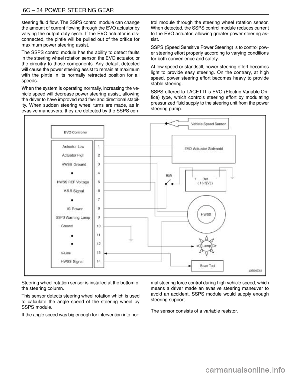
steering fluid flow. The SSPS control module can change
the amount of current flowing through the EVO actuator by
varying the output duty cycle. If the EVO actuator is dis-
connected, the pintle will be pulled out of the orifice for
maximum power steering assist.
The SSPS control module has the ability to detect faults
in the steering wheel rotation sensor, the EVO actuator, or
the circuitry to those components. Any default detected
will cause the power steering assist to remain at maximum
with the pintle in its normally retracted position for all
speeds.
When the system is operating normally, increasing the ve-
hicle speed will decrease power steering assist, allowing
the driver to have improved road feel and directional stabil-
ity. When sudden steering wheel turns are made, as in
evasive maneuvers, they are detected by the SSPS con-trol module through the steering wheel rotation sensor.
When detected, the SSPS control module reduces current
to the EVO actuator, allowing greater power steering as-
sist.
SSPS (Speed Sensitive Power Steering) is to control pow-
er steering effort properly according to varying conditions
for both convenience and safety.
At low speed or standstill, power steering effort becomes
light to provide easy steering. On the contrary, at high
speed, power steering effort becomes heavy to provide
stable steering.
SSPS offered to LACETTI is EVO (Electric Variable Ori-
fice) type, which controls steering effort by modulating
pressurized fluid supply to the steering unit from the power
steering pump.
Steering wheel rotation sensor is installed at the bottom of
the steering column.
This sensor detects steering wheel rotation which is used
to calculate the angle speed of the steering wheel by
SSPS module.
If the angle speed was big enough for intervention into nor-mal steering force control during high vehicle speed, which
means a driver made an evasive steering maneuver to
avoid an accident, SSPS module would supply enough
steering support.
The sensor consists of a variable resistor.
Page 1953 of 2643

6C – 36IPOWER STEERING GEAR
DAEWOO V–121 BL4
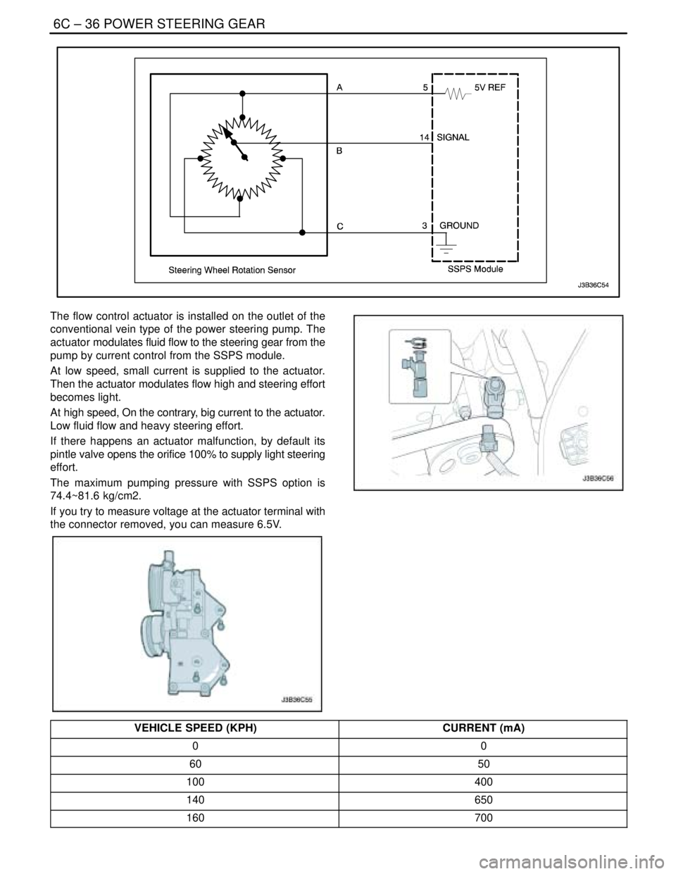
The flow control actuator is installed on the outlet of the
conventional vein type of the power steering pump. The
actuator modulates fluid flow to the steering gear from the
pump by current control from the SSPS module.
At low speed, small current is supplied to the actuator.
Then the actuator modulates flow high and steering effort
becomes light.
At high speed, On the contrary, big current to the actuator.
Low fluid flow and heavy steering effort.
If there happens an actuator malfunction, by default its
pintle valve opens the orifice 100% to supply light steering
effort.
The maximum pumping pressure with SSPS option is
74.4~81.6 kg/cm2.
If you try to measure voltage at the actuator terminal with
the connector removed, you can measure 6.5V.
VEHICLE SPEED (KPH)CURRENT (mA)
00
6050
100400
140650
160700
Page 1954 of 2643
![DAEWOO LACETTI 2004 Service Repair Manual POWER STEERING GEAR 6C – 37
DAEWOO V–121 BL4
[Vehicle Speed – Actuator Current Relation]
SOLENOID RESISTANCE
13 W
The control module is installed on the right side of the au-
dio and can be acc DAEWOO LACETTI 2004 Service Repair Manual POWER STEERING GEAR 6C – 37
DAEWOO V–121 BL4
[Vehicle Speed – Actuator Current Relation]
SOLENOID RESISTANCE
13 W
The control module is installed on the right side of the au-
dio and can be acc](/manual-img/54/56877/w960_56877-1953.png)
POWER STEERING GEAR 6C – 37
DAEWOO V–121 BL4
[Vehicle Speed – Actuator Current Relation]
SOLENOID RESISTANCE
13 W
The control module is installed on the right side of the au-
dio and can be accessible after the glove box is removed.
It receives signals from the vehicle speed sensor and the
steering wheel rotation sensor and processes them to de-
cide proper fluid flow through the actuator.
It also has a self–diagnosis. If it detects any malfunction,
it starts default mode, which is basically actuator full open
for light steering effort.
TERMINALCOLORFUNCTION
1SBActuator Low
2VActuator High
3BWSteering Wheel Sensor Ground
4–Not used
5GrSteering Wheel Sensor 5V ref.
6GWVSS
7–Not Used
8PIGN ON
9BrWarning Lamp
10BWGround
11–Not Used
12–Not Used
13LDiagnosis
14SBSteering Wheel Sensor Signal