2004 DAEWOO LACETTI light
[x] Cancel search: lightPage 173 of 2643
1.8L DOHC ENGINE MECHANICAL 1C2 – 53
DAEWOO V–121 BL4
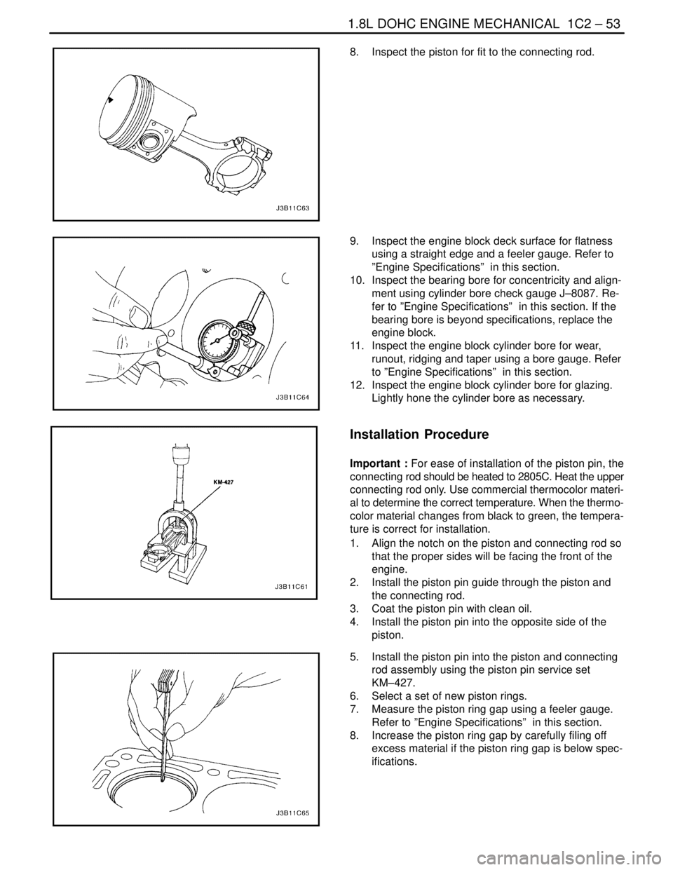
8. Inspect the piston for fit to the connecting rod.
9. Inspect the engine block deck surface for flatness
using a straight edge and a feeler gauge. Refer to
”Engine Specifications” in this section.
10. Inspect the bearing bore for concentricity and align-
ment using cylinder bore check gauge J–8087. Re-
fer to ”Engine Specifications” in this section. If the
bearing bore is beyond specifications, replace the
engine block.
11. Inspect the engine block cylinder bore for wear,
runout, ridging and taper using a bore gauge. Refer
to ”Engine Specifications” in this section.
12. Inspect the engine block cylinder bore for glazing.
Lightly hone the cylinder bore as necessary.
Installation Procedure
Important : For ease of installation of the piston pin, the
connecting rod should be heated to 2805C. Heat the upper
connecting rod only. Use commercial thermocolor materi-
al to determine the correct temperature. When the thermo-
color material changes from black to green, the tempera-
ture is correct for installation.
1. Align the notch on the piston and connecting rod so
that the proper sides will be facing the front of the
engine.
2. Install the piston pin guide through the piston and
the connecting rod.
3. Coat the piston pin with clean oil.
4. Install the piston pin into the opposite side of the
piston.
5. Install the piston pin into the piston and connecting
rod assembly using the piston pin service set
KM–427.
6. Select a set of new piston rings.
7. Measure the piston ring gap using a feeler gauge.
Refer to ”Engine Specifications” in this section.
8. Increase the piston ring gap by carefully filing off
excess material if the piston ring gap is below spec-
ifications.
Page 181 of 2643
1.8L DOHC ENGINE MECHANICAL 1C2 – 61
DAEWOO V–121 BL4
4. Inspect the dimension for the valve seat width.
S Intake: 1.2 to 1.4 mm (0.047 to 0.055 inch).
S Exhaust: 1.4 to 1.8 mm (0.055 to 0.070 inch).
5. Inspect the assembly height of the intake valves
and the exhaust valves. If the dimension is exceed-
ed, install new valves. Inspect the assembly height
of the intake valves and the exhaust valves again. If
the valve assembly height is still too large despite
replacing the valves, replace the cylinder head.
Assembly Procedure
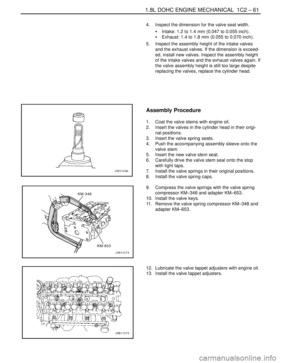
1. Coat the valve stems with engine oil.
2. Insert the valves in the cylinder head in their origi-
nal positions.
3. Insert the valve spring seats.
4. Push the accompanying assembly sleeve onto the
valve stem.
5. Insert the new valve stem seat.
6. Carefully drive the valve stem seal onto the stop
with light taps.
7. Install the valve springs in their original positions.
8. Install the valve spring caps.
9. Compress the valve springs with the valve spring
compressor KM–348 and adapter KM–653.
10. Install the valve keys.
11. Remove the valve spring compressor KM–348 and
adapter KM–653.
12. Lubricate the valve tappet adjusters with engine oil.
13. Install the valve tappet adjusters.
Page 187 of 2643
1.8L DOHC ENGINE MECHANICAL 1C2 – 67
DAEWOO V–121 BL4
3. Install the crankshaft.
4. Install the lower crankshaft bearings in the bearing
caps.
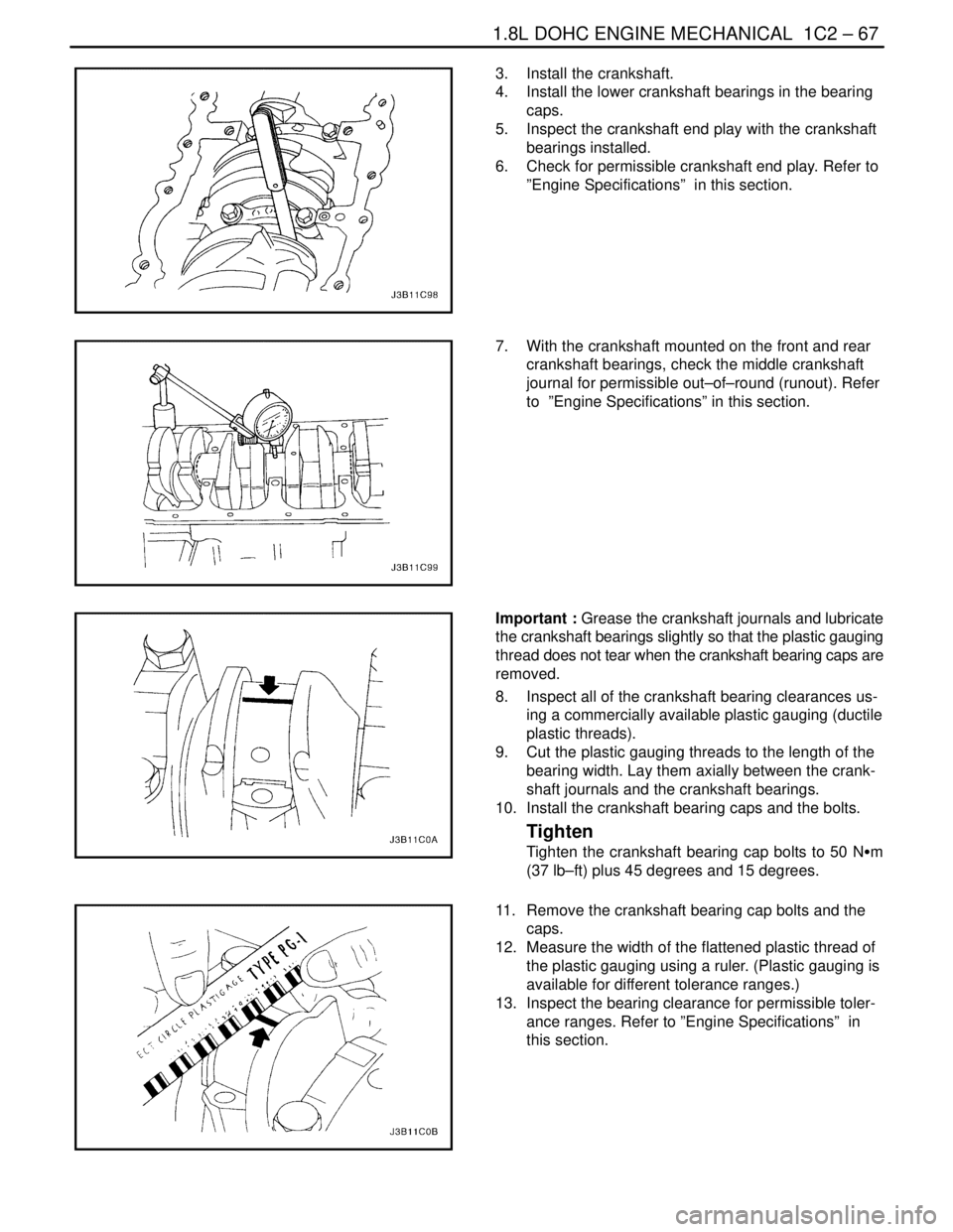
5. Inspect the crankshaft end play with the crankshaft
bearings installed.
6. Check for permissible crankshaft end play. Refer to
”Engine Specifications” in this section.
7. With the crankshaft mounted on the front and rear
crankshaft bearings, check the middle crankshaft
journal for permissible out–of–round (runout). Refer
to ”Engine Specifications” in this section.
Important : Grease the crankshaft journals and lubricate
the crankshaft bearings slightly so that the plastic gauging
thread does not tear when the crankshaft bearing caps are
removed.
8. Inspect all of the crankshaft bearing clearances us-
ing a commercially available plastic gauging (ductile
plastic threads).
9. Cut the plastic gauging threads to the length of the
bearing width. Lay them axially between the crank-
shaft journals and the crankshaft bearings.
10. Install the crankshaft bearing caps and the bolts.
Tighten
Tighten the crankshaft bearing cap bolts to 50 NSm
(37 lb–ft) plus 45 degrees and 15 degrees.
11. Remove the crankshaft bearing cap bolts and the
caps.
12. Measure the width of the flattened plastic thread of
the plastic gauging using a ruler. (Plastic gauging is
available for different tolerance ranges.)
13. Inspect the bearing clearance for permissible toler-
ance ranges. Refer to ”Engine Specifications” in
this section.
Page 188 of 2643
1C2 – 68I1.8L DOHC ENGINE MECHANICAL
DAEWOO V–121 BL4
14. Apply a bead of adhesive sealing compound to the
grooves of the crankshaft bearing caps.
15. Install the crankshaft bearing caps to the engine
block.
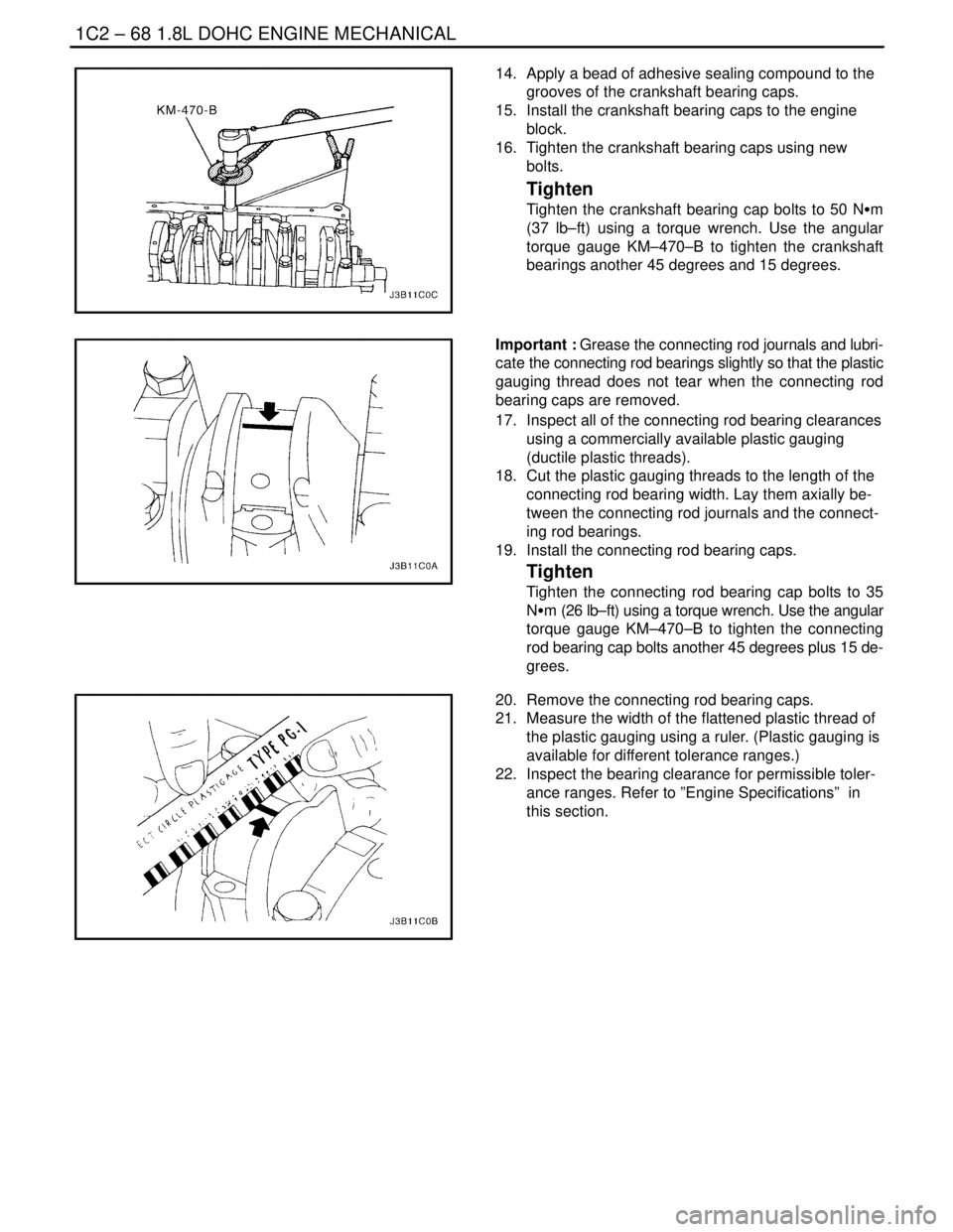
16. Tighten the crankshaft bearing caps using new
bolts.
Tighten
Tighten the crankshaft bearing cap bolts to 50 NSm
(37 lb–ft) using a torque wrench. Use the angular
torque gauge KM–470–B to tighten the crankshaft
bearings another 45 degrees and 15 degrees.
Important : Grease the connecting rod journals and lubri-
cate the connecting rod bearings slightly so that the plastic
gauging thread does not tear when the connecting rod
bearing caps are removed.
17. Inspect all of the connecting rod bearing clearances
using a commercially available plastic gauging
(ductile plastic threads).
18. Cut the plastic gauging threads to the length of the
connecting rod bearing width. Lay them axially be-
tween the connecting rod journals and the connect-
ing rod bearings.
19. Install the connecting rod bearing caps.
Tighten
Tighten the connecting rod bearing cap bolts to 35
NSm (26 lb–ft) using a torque wrench. Use the angular
torque gauge KM–470–B to tighten the connecting
rod bearing cap bolts another 45 degrees plus 15 de-
grees.
20. Remove the connecting rod bearing caps.
21. Measure the width of the flattened plastic thread of
the plastic gauging using a ruler. (Plastic gauging is
available for different tolerance ranges.)
22. Inspect the bearing clearance for permissible toler-
ance ranges. Refer to ”Engine Specifications” in
this section.
Page 193 of 2643
1.8L DOHC ENGINE MECHANICAL 1C2 – 73
DAEWOO V–121 BL4
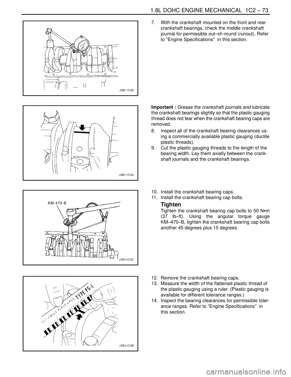
7. With the crankshaft mounted on the front and rear
crankshaft bearings, check the middle crankshaft
journal for permissible out–of–round (runout). Refer
to ”Engine Specifications” in this section.
Important : Grease the crankshaft journals and lubricate
the crankshaft bearings slightly so that the plastic gauging
thread does not tear when the crankshaft bearing caps are
removed.
8. Inspect all of the crankshaft bearing clearances us-
ing a commercially available plastic gauging (ductile
plastic threads).
9. Cut the plastic gauging threads to the length of the
bearing width. Lay them axially between the crank-
shaft journals and the crankshaft bearings.
10. Install the crankshaft bearing caps.
11. Install the crankshaft bearing cap bolts.
Tighten
Tighten the crankshaft bearing cap bolts to 50 NSm
(37 lb–ft). Using the angular torque gauge
KM–470–B, tighten the crankshaft bearing cap bolts
another 45 degrees plus 15 degrees.
12. Remove the crankshaft bearing caps.
13. Measure the width of the flattened plastic thread of
the plastic gauging using a ruler. (Plastic gauging is
available for different tolerance ranges.)
14. Inspect the bearing clearances for permissible toler-
ance ranges. Refer to ”Engine Specifications” in
this section.
Page 194 of 2643
1C2 – 74I1.8L DOHC ENGINE MECHANICAL
DAEWOO V–121 BL4
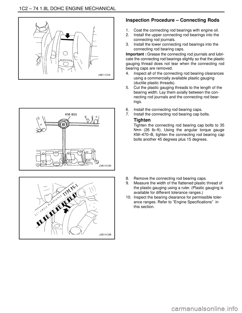
Inspection Procedure – Connecting Rods
1. Coat the connecting rod bearings with engine oil.
2. Install the upper connecting rod bearings into the
connecting rod journals.
3. Install the lower connecting rod bearings into the
connecting rod bearing caps.
Important : Grease the connecting rod journals and lubri-
cate the connecting rod bearings slightly so that the plastic
gauging thread does not tear when the connecting rod
bearing caps are removed.
4. Inspect all of the connecting rod bearing clearances
using a commercially available plastic gauging
(ductile plastic threads).
5. Cut the plastic gauging threads to the length of the
bearing width. Lay them axially between the con-
necting rod journals and the connecting rod bear-
ings.
6. Install the connecting rod bearing caps.
7. Install the connecting rod bearing cap bolts.
Tighten
Tighten the connecting rod bearing cap bolts to 35
NSm (26 lb–ft). Using the angular torque gauge
KM–470–B, tighten the connecting rod bearing cap
bolts another 45 degrees plus 15 degrees.
8. Remove the connecting rod bearing caps.
9. Measure the width of the flattened plastic thread of
the plastic gauging using a ruler. (Plastic gauging is
available for different tolerance ranges.)
10. Inspect the bearing clearance for permissible toler-
ance ranges. Refer to ”Engine Specifications” in
this section.
Page 213 of 2643

1D – 18IENGINE COOLING
DAEWOO V–121 BL4
GENERAL DESCRIPTION
AND SYSTEM OPERATION
GENERAL DESCRIPTION
The cooling system maintains the engine temperature at
an efficient level during all engine operating conditions.
When the engine is cold, the cooling system cools the en-
gine slowly or not at all. This slow cooling of the engine al-
lows the engine to warm up quickly.
The cooling system includes a radiator and recovery sub-
system, cooling fans, a thermostat and housing, a coolant
pump, and a coolant pump drive belt. The timing belt
drives the coolant pump.
All components must function properly in order for the
cooling system to operate. The coolant pump draws the
coolant from the radiator. The coolant then circulates
through water jackets in the engine block, the intake man-
ifold, and the cylinder head. When the coolant reaches the
operating temperature of the thermostat, the thermostat
opens. The coolant then goes back to the radiator where
it cools.
This system directs some coolant through the hoses to the
heater core. This provides for heating and defrosting. The
surge tank is connected to the radiator to recover the cool-
ant displaced by expansion from the high temperatures.
The surge tank maintains the correct coolant level.
The cooling system for this vehicle has no radiator cap or
filler neck. The coolant is added to the cooling system
through the surge tank.
RADIATOR
This vehicle has a lightweight tube–and–fin aluminum ra-
diator. Plastic tanks are mounted on the right and the left
sides of the radiator core.
On vehicles equipped with automatic transaxles, the
transaxle fluid cooler lines run through the left radiator
tank. A radiator drain cock is on this radiator.
To drain the cooling system, open the drain cock.
SURGE TANK
The surge tank is a transparent plastic reservoir, similar to
the windshield washer reservoir.
The surge tank is connected to the radiator by a hose and
to the engine cooling system by another hose. As the ve-
hicle is driven, the engine coolant heats and expands. The
portion of the engine coolant displaced by this expansion
flows from the radiator and the engine into the surge tank.
The air trapped in the radiator and the engine is degassed
into the surge tank.When the engine stops, the engine coolant cools and con-
tracts. The displaced engine coolant is then drawn back
into the radiator and the engine. This keeps the radiator
filled with the coolant to the desired level at all times and
increases the cooling efficiency.
Maintain the coolant level between the MIN and the MAX
marks on the surge tank when the system is cold.
WATER PUMP
The belt–driven centrifugal water pump consists of an im-
peller, a drive shaft, and a belt pulley. The water pump is
mounted on the front of the transverse–mounted engine,
and is driven by the timing belt.
The impeller is supported by a completely sealed bearing.
The water pump is serviced as an assembly and, there-
fore, cannot be disassembled.
THERMOSTAT
A wax pellet–type thermostat controls the flow of the en-
gine coolant through the engine cooling system. The ther-
mostat is mounted in the thermostat housing to the front
of the cylinder head.
The thermostat stops the flow of the engine coolant from
the engine to the radiator in order to provide faster warm–
up, and to regulate the coolant temperature. The thermo-
stat remains closed while the engine coolant is cold, pre-
venting circulation of the engine coolant through the
radiator. At this point, the engine coolant is allowed to cir-
culate only throughout the heater core to warm it quickly
and evenly.
As the engine warms, the thermostat opens. This allows
the engine coolant to flow through the radiator, where the
heat is dissipated through the radiator. This opening and
closing of the thermostat permits enough engine coolant
to enter the radiator to keep the engine within proper en-
gine temperature operating limits.
The wax pellet in the thermostat is hermetically sealed in
a metal case. The wax element of the thermostat expands
when it is heated and contracts when it is cooled.
As the vehicle is driven and the engine warms, the engine
coolant temperature increases. When the engine coolant
reaches a specified temperature, the wax pellet element
in the thermostat expands and exerts pressure against the
metal case, forcing the valve open. This allows the engine
coolant to flow through the engine cooling system and cool
the engine.
As the wax pellet cools, the contraction allows a spring to
close the valve.
The thermostat begins to open at 87°C (189°F) and is fully
open at 102°C (216°F). The thermostat closes at 86°C
(187°F).
Page 220 of 2643

1E – 6IENGINE ELECTRICAL
DAEWOO V–121 BL4
DIAGNOSIS
NO CRANK
StepActionValue(s)YesNo
11. Turn the headlamps ON.
2. Turn the dome lamps ON.
3. Turn the ignition to START.
Did the lights dim or go out?–Go to Step 2Go to Step 8
2Check the battery state of charge.
Is the green eye showing from the built–in hydrome-
ter?–Go to Step 3Go to
”Charging Pro-
cedure”
31. Connect the voltmeter positive lead to the posi-
tive battery terminal.
2. Connect the voltmeter negative lead to the
negative battery terminal.
3. Turn the ignition to START.
Does the voltmeter indicate the value specified?< 9.6 vGo to
”Charging Pro-
cedure”Go to Step 4
41. Connect the voltmeter negative lead to the
negative battery terminal.
2. Connect the positive voltmeter lead to the en-
gine block.
Does the voltmeter indicate the value specified?> 0.5 vGo to Step 5Go to Step 6
5Clean, tighten, or replace the negative battery cable.
Is the repair complete?–System OK–
61. Connect the voltmeter positive lead to the start-
er ”B+” terminal.
2. Connect the voltmeter negative lead to the
negative battery terminal.
Does the voltmeter indicate the value specified?< 9 vGo to Step 7Go to Step 13
7Clean, tighten, or replace the positive battery cable.
Is the repair complete?–System OK–
8Inspect the engine fuse block fuse Ef5.
Is the fuse OK?–Go to Step 10Go to Step 9
9Inspect the engine fuse block fuse Ef4.
Is the fuse OK?–System OK–
10Check the connection at the starter ”ST” terminal.
Is the connection OK?–Go to Step 12Go to Step 11
11Clean or tighten the connection as needed.
Is the repair complete?–System OK–
121. Connect the voltmeter positive lead to the start-
er ”ST” terminal.
2. Connect the voltmeter negative lead to the
negative battery terminal.
3. Turn the ignition to START.
Does the voltmeter indicate the value specified?< 7 vGo to Step 13Go to Step 14
13Repair or replace the starter as needed.
Is the repair complete?–System OK–
14Determine the type of transaxle on the vehicle.
Is the vehicle equipped with an automatic transaxle?–Go to Step 15Go to Step 32