2004 DAEWOO LACETTI key battery
[x] Cancel search: key batteryPage 582 of 2643

1F – 336IENGINE CONTROLS
DAEWOO V–121 BL4
DIAGNOSTIC TROUBLE CODE (DTC) P1628
IMMOBILIZER NO SUCCESSFUL COMMUNICATION
Circuit Description
When the ignition switch is turned to ON, the key tested
by immobilizer anti–theft system. While the key code is be-
ing read by immobilizer control unit or integrated anti–theft
control unit, the engine can start run with any key that will
turn the lock cylinder. the key code is read and compared
with key codes that have been stored in the memory of the
immobilizer control unit. If a valid key is detected, the im-
mobilizer control unit sends a serial data release message
to the Engine Control Module (ECM). Included in the re-
lease message is an identification (ID) code which as-
sures that neither the immobilizer control unit nor the ECM
have been substituted to defeat the system. If the ECM re-
ceives an invalid release message, the ECM performs the
following action:
S Disable the fuel injector circuit.
S Disable the fuel pump circuit.
S Disable the ignition coil.
S A Diagnostic Trouble Code (DTC) will stored if de-
tect communication link failure between the ECM
and immobilizer control unit.Conditions for Setting the DTC
S No safety security strategy allowed.
S Time–out delay has elapsed without successful
communication or a transmission key ON/OFF oc-
curred before a successful communication.
Action Taken When the DTC Sets
S The Malfunction Indicator Lamp (MIL) will not illumi-
nate.
S The ECM will store conditions which were present
when the DTC was set as Failure Records data
only.
S This information will not be stored in the Freeze
Frame data.
Conditions for Clearing the MIL/DTC
S A history DTC will clear after 40 consecutive warm–
up cycles without a fault.
S DTC(s) can be cleared by using the scan tool.
S Disconnecting the ECM battery feed for more than
10 seconds.
Page 584 of 2643
1F – 338IENGINE CONTROLS
DAEWOO V–121 BL4
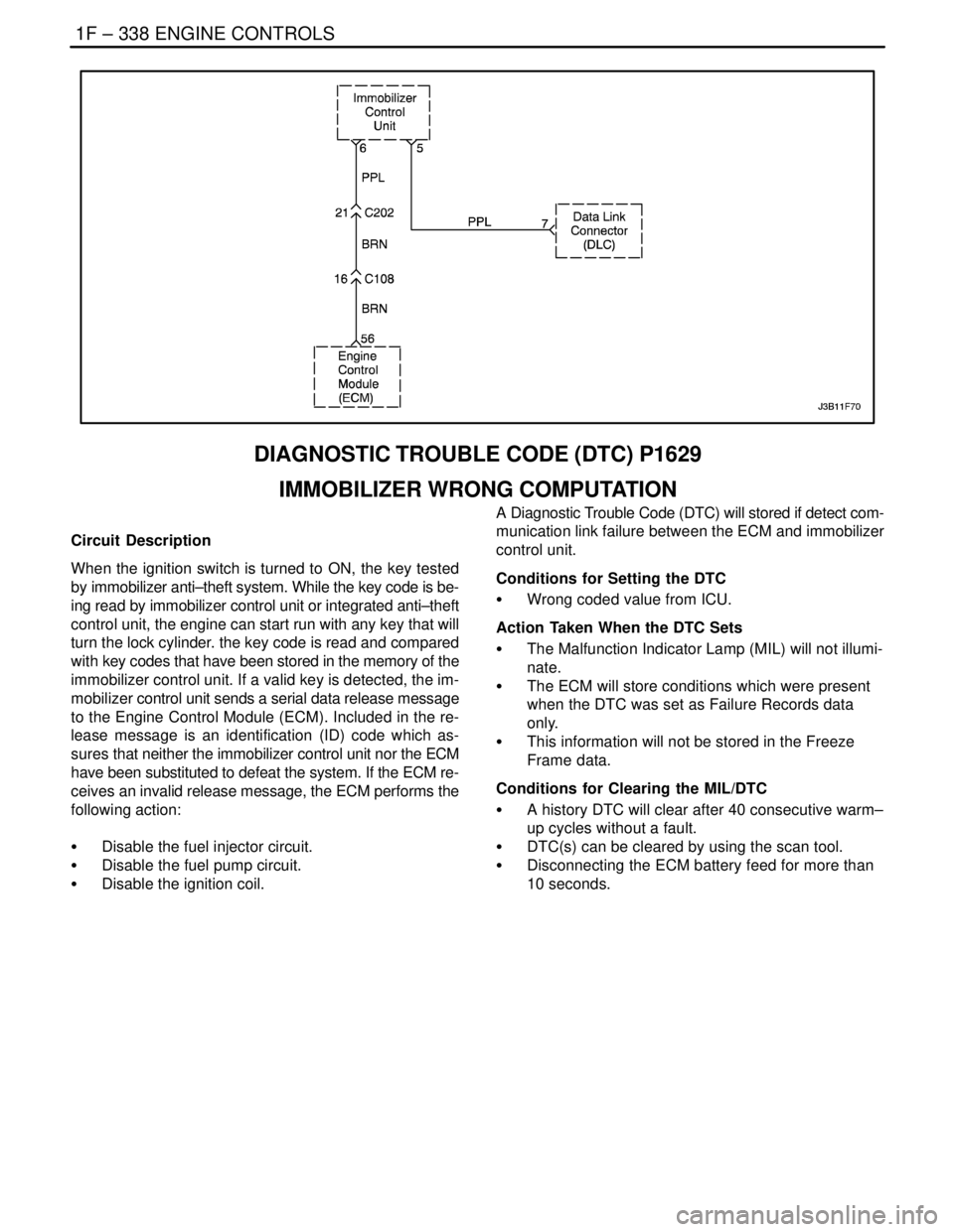
DIAGNOSTIC TROUBLE CODE (DTC) P1629
IMMOBILIZER WRONG COMPUTATION
Circuit Description
When the ignition switch is turned to ON, the key tested
by immobilizer anti–theft system. While the key code is be-
ing read by immobilizer control unit or integrated anti–theft
control unit, the engine can start run with any key that will
turn the lock cylinder. the key code is read and compared
with key codes that have been stored in the memory of the
immobilizer control unit. If a valid key is detected, the im-
mobilizer control unit sends a serial data release message
to the Engine Control Module (ECM). Included in the re-
lease message is an identification (ID) code which as-
sures that neither the immobilizer control unit nor the ECM
have been substituted to defeat the system. If the ECM re-
ceives an invalid release message, the ECM performs the
following action:
S Disable the fuel injector circuit.
S Disable the fuel pump circuit.
S Disable the ignition coil.A Diagnostic Trouble Code (DTC) will stored if detect com-
munication link failure between the ECM and immobilizer
control unit.
Conditions for Setting the DTC
S Wrong coded value from ICU.
Action Taken When the DTC Sets
S The Malfunction Indicator Lamp (MIL) will not illumi-
nate.
S The ECM will store conditions which were present
when the DTC was set as Failure Records data
only.
S This information will not be stored in the Freeze
Frame data.
Conditions for Clearing the MIL/DTC
S A history DTC will clear after 40 consecutive warm–
up cycles without a fault.
S DTC(s) can be cleared by using the scan tool.
S Disconnecting the ECM battery feed for more than
10 seconds.
Page 590 of 2643
1F – 344IENGINE CONTROLS
DAEWOO V–121 BL4
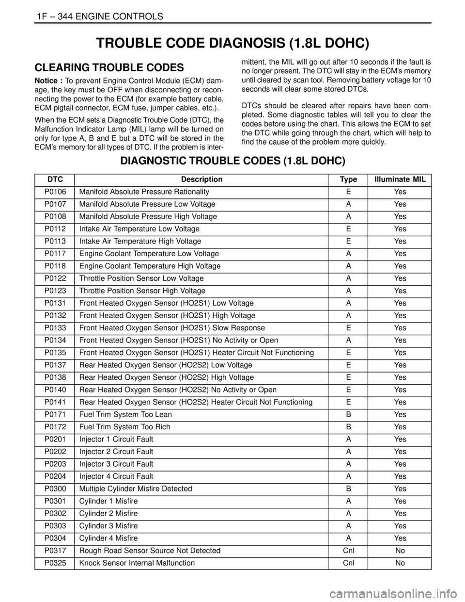
TROUBLE CODE DIAGNOSIS (1.8L DOHC)
CLEARING TROUBLE CODES
Notice : To prevent Engine Control Module (ECM) dam-
age, the key must be OFF when disconnecting or recon-
necting the power to the ECM (for example battery cable,
ECM pigtail connector, ECM fuse, jumper cables, etc.).
When the ECM sets a Diagnostic Trouble Code (DTC), the
Malfunction Indicator Lamp (MIL) lamp will be turned on
only for type A, B and E but a DTC will be stored in the
ECM’s memory for all types of DTC. If the problem is inter-mittent, the MIL will go out after 10 seconds if the fault is
no longer present. The DTC will stay in the ECM’s memory
until cleared by scan tool. Removing battery voltage for 10
seconds will clear some stored DTCs.
DTCs should be cleared after repairs have been com-
pleted. Some diagnostic tables will tell you to clear the
codes before using the chart. This allows the ECM to set
the DTC while going through the chart, which will help to
find the cause of the problem more quickly.
DIAGNOSTIC TROUBLE CODES (1.8L DOHC)
DTCDescriptionTypeIlluminate MIL
P0106Manifold Absolute Pressure RationalityEYe s
P0107Manifold Absolute Pressure Low VoltageAYe s
P0108Manifold Absolute Pressure High VoltageAYe s
P0112Intake Air Temperature Low VoltageEYe s
P0113Intake Air Temperature High VoltageEYe s
P0117Engine Coolant Temperature Low VoltageAYe s
P0118Engine Coolant Temperature High VoltageAYe s
P0122Throttle Position Sensor Low VoltageAYe s
P0123Throttle Position Sensor High VoltageAYe s
P0131Front Heated Oxygen Sensor (HO2S1) Low VoltageAYe s
P0132Front Heated Oxygen Sensor (HO2S1) High VoltageAYe s
P0133Front Heated Oxygen Sensor (HO2S1) Slow ResponseEYe s
P0134Front Heated Oxygen Sensor (HO2S1) No Activity or OpenAYe s
P0135Front Heated Oxygen Sensor (HO2S1) Heater Circuit Not FunctioningEYe s
P0137Rear Heated Oxygen Sensor (HO2S2) Low VoltageEYe s
P0138Rear Heated Oxygen Sensor (HO2S2) High VoltageEYe s
P0140Rear Heated Oxygen Sensor (HO2S2) No Activity or OpenEYe s
P0141Rear Heated Oxygen Sensor (HO2S2) Heater Circuit Not FunctioningEYe s
P0171Fuel Trim System Too LeanBYe s
P0172Fuel Trim System Too RichBYe s
P0201Injector 1 Circuit FaultAYe s
P0202Injector 2 Circuit FaultAYe s
P0203Injector 3 Circuit FaultAYe s
P0204Injector 4 Circuit FaultAYe s
P0300Multiple Cylinder Misfire DetectedBYe s
P0301Cylinder 1 MisfireAYe s
P0302Cylinder 2 MisfireAYe s
P0303Cylinder 3 MisfireAYe s
P0304Cylinder 4 MisfireAYe s
P0317Rough Road Sensor Source Not DetectedCnlNo
P0325Knock Sensor Internal MalfunctionCnlNo
Page 638 of 2643

1F – 392IENGINE CONTROLS
DAEWOO V–121 BL4
Conditions for Clearing the MIL/DTC
S The MIL will turn off after four consecutive ignition
cycles in which the diagnostic runs without a fault.
S A history DTC will clear after 40 consecutive warm–
up cycles without a fault.
S The DTC(s) can be cleared by using the scan tool.
S Disconnecting the ECM battery feed for more than
10 seconds.
Diagnostic Aids
Check for the following conditions:
S Rich exhaust – An overly rich exhaust may load the
catalyst, causing high HO2S2 signal voltages.
S Silicone contamination – A false rich condition may
be caused by silicone contamination of the HO2S2.
This will be indicated by a powdery white deposit on
the sensor.
S Faulty HO2S2 – If HO2S2 is internally shorted, the
HO2S2 voltage displayed on a scan tool will be
over 1 volt. Disconnect the HO2S2 and jumper the
sensor low circuit to engine ground; if the displayed
voltage goes from over 1000 millivolt to around 450
millivolt, replace the HO2S2.S Intermittent test – Observe HO2S2 on the scan tool
while moving related connectors and the wiring har-
ness with the key in the ON position. If the failure is
induced, the HO2S2 display will change. This may
help isolate the location of the malfunction.
Test Description
Number(s) below refer to the step number(s) on the Diag-
nostic Table.
1. The On–Board Diagnostic (EOBD) System Check
prompts the technician to complete some basic
checks and store the freeze frame and failure re-
cords data on the scan tool if applicable. This
creates an electronic copy of the data taken when
the malfunction occurred. The information is then
stored on the scan tool for later reference.
2. This step determines if DTC P0138 is the result of
a hard failure or an intermittent condition.
5. Disconnecting the HO2S2 and jumpering the sen-
sor signal circuit and the sensor low circuit to
ground should cause the scan tool to display
HO2S2 voltage below 100 mv (0.1 v). If the signal
voltage is still high, the ECM is malfunctioning.
6. The replacement ECM must be reprogrammed.
Refer to the latest Techline procedure for ECM re-
programming.
DTC P0138 – Rear Heated Oxygen Sensor (HO2S2) High Voltage
StepActionValue(s)YesNo
1Perform an On–Board Diagnostic (EOBD) System
Check.
Was the check performed?–Go to Step 2Go to
”On–Board
Diagnostic Sys-
tem Check”
21. Install a scan tool to the Data Link Connector
(DLC).
2. Turn the ignition ON.
Is the Rear Heated Oxygen Sensor (HO2S2) volt-
age above the value specified?0.9 VGo to Step 4Go to Step 3
31. Review the Freeze Frame data and note the
parameters.
2. Operate the vehicle within the Freeze frame
conditions and Conditions For Setting the DTC
as noted.
Is the HO2S2 voltage above the specified value?0.9 VGo to Step 4Go to Step 9
41. Turn the ignition OFF.
2. Disconnect HO2S2 connector.
3. Disconnect the Engine Control Module (ECM)
connector.
4. With voltmeter connected to ground, probe the
HO2S2 high signal circuit, terminal K36.
Is the voltage within the specified value?±0 VGo to Step 5Go to Step 6
Page 768 of 2643
1F – 522IENGINE CONTROLS
DAEWOO V–121 BL4
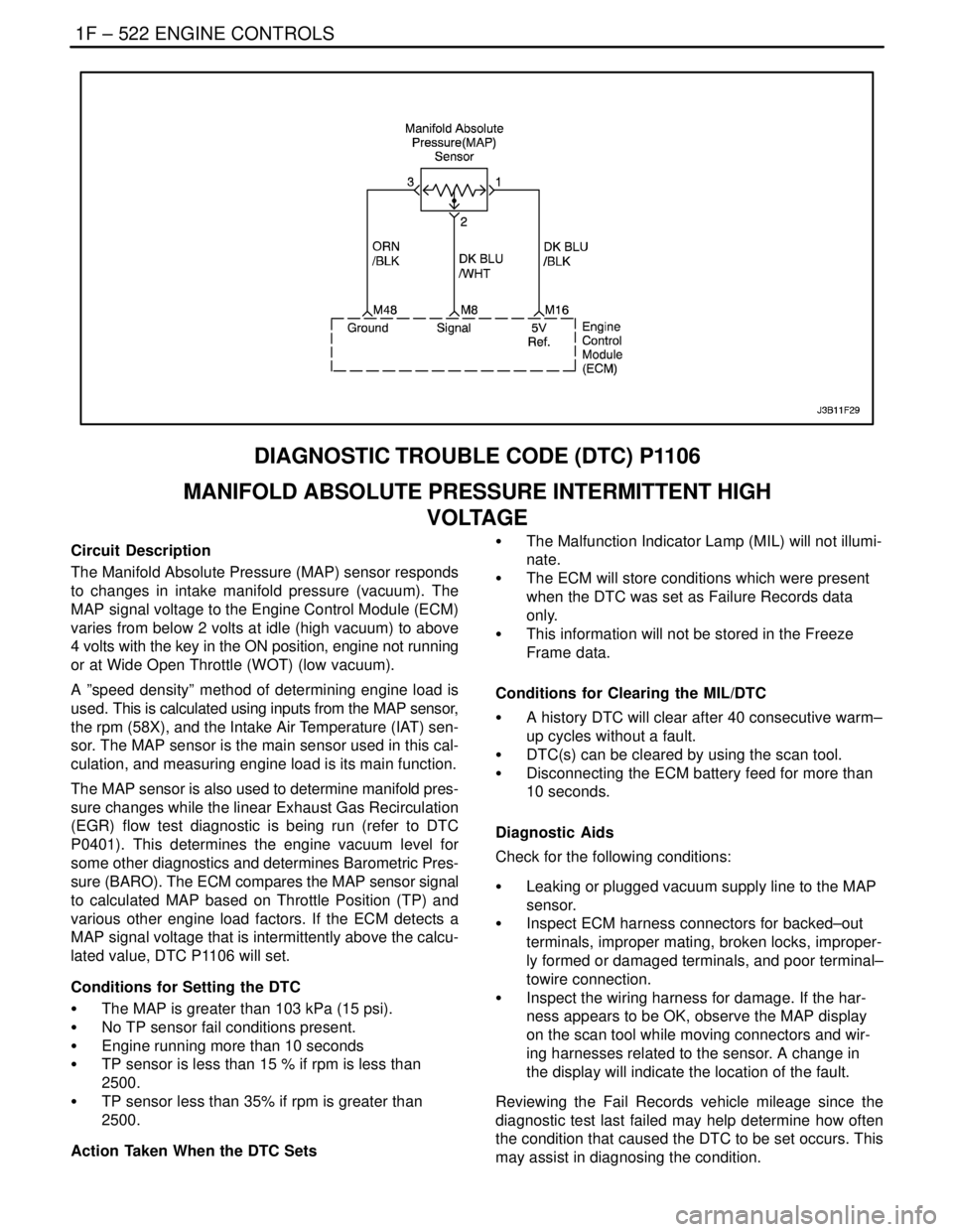
DIAGNOSTIC TROUBLE CODE (DTC) P1106
MANIFOLD ABSOLUTE PRESSURE INTERMITTENT HIGH
VOLTAGE
Circuit Description
The Manifold Absolute Pressure (MAP) sensor responds
to changes in intake manifold pressure (vacuum). The
MAP signal voltage to the Engine Control Module (ECM)
varies from below 2 volts at idle (high vacuum) to above
4 volts with the key in the ON position, engine not running
or at Wide Open Throttle (WOT) (low vacuum).
A ”speed density” method of determining engine load is
used. This is calculated using inputs from the MAP sensor,
the rpm (58X), and the Intake Air Temperature (IAT) sen-
sor. The MAP sensor is the main sensor used in this cal-
culation, and measuring engine load is its main function.
The MAP sensor is also used to determine manifold pres-
sure changes while the linear Exhaust Gas Recirculation
(EGR) flow test diagnostic is being run (refer to DTC
P0401). This determines the engine vacuum level for
some other diagnostics and determines Barometric Pres-
sure (BARO). The ECM compares the MAP sensor signal
to calculated MAP based on Throttle Position (TP) and
various other engine load factors. If the ECM detects a
MAP signal voltage that is intermittently above the calcu-
lated value, DTC P1106 will set.
Conditions for Setting the DTC
S The MAP is greater than 103 kPa (15 psi).
S No TP sensor fail conditions present.
S Engine running more than 10 seconds
S TP sensor is less than 15 % if rpm is less than
2500.
S TP sensor less than 35% if rpm is greater than
2500.
Action Taken When the DTC SetsS The Malfunction Indicator Lamp (MIL) will not illumi-
nate.
S The ECM will store conditions which were present
when the DTC was set as Failure Records data
only.
S This information will not be stored in the Freeze
Frame data.
Conditions for Clearing the MIL/DTC
S A history DTC will clear after 40 consecutive warm–
up cycles without a fault.
S DTC(s) can be cleared by using the scan tool.
S Disconnecting the ECM battery feed for more than
10 seconds.
Diagnostic Aids
Check for the following conditions:
S Leaking or plugged vacuum supply line to the MAP
sensor.
S Inspect ECM harness connectors for backed–out
terminals, improper mating, broken locks, improper-
ly formed or damaged terminals, and poor terminal–
towire connection.
S Inspect the wiring harness for damage. If the har-
ness appears to be OK, observe the MAP display
on the scan tool while moving connectors and wir-
ing harnesses related to the sensor. A change in
the display will indicate the location of the fault.
Reviewing the Fail Records vehicle mileage since the
diagnostic test last failed may help determine how often
the condition that caused the DTC to be set occurs. This
may assist in diagnosing the condition.
Page 770 of 2643

1F – 524IENGINE CONTROLS
DAEWOO V–121 BL4
DIAGNOSTIC TROUBLE CODE (DTC) P1107
MANIFOLD ABSOLUTE PRESSURE INTERMITTENT LOW
VOLTAGE
Circuit Description
The Manifold Absolute Pressure (MAP) sensor responds
to changes in intake manifold pressure (vacuum). The
MAP signal voltage to the Engine Control Module (ECM)
varies from below 2 volts at idle (high vacuum) to above
4 volts with the key in the ON position, engine not running
or at Wide Open Throttle (WOT) (low vacuum).
A ”speed density” method of determining engine load is
used. This is calculated using inputs from the MAP sensor,
the rpm (58X), and the Intake Air Temperature (IAT) sen-
sor. The MAP sensor is the main sensor used in this cal-
culation, and measuring engine load is its main function.
The MAP sensor is also used to determine manifold pres-
sure changes while the linear Exhaust Gas Recirculation
(EGR) flow test diagnostic is being run (refer to DTC
P0401). This determines the engine vacuum level for
some other diagnostics and determines Barometric Pres-
sure (BARO). The ECM compares the MAP sensor signal
to calculated MAP based on Throttle Position (TP) and
various other engine load factors. If the ECM detects a
MAP signal voltage that is intermittently below the calcu-
lated value, DTC P1107 will set.
Conditions for Setting the DTC
S The MAP is less than 12 kPa (1.7 psi).
S No TP sensor fail conditions present.
S TP sensor is greater than 0% if rpm is less than
1000.
S TP sensor less than 5% if rpm is greater than 1000.
S System voltage is between 11–11.5 volts.
Action Taken When the DTC SetsS The Malfunction Indicator Lamp (MIL) will not illumi-
nate.
S The ECM will store conditions which were present
when the DTC was set as Failure Records data
only.
S This information will not be stored in the Freeze
Frame data.
Conditions for Clearing the MIL/DTC
S A history DTC will clear after 40 consecutive warm–
up cycles without a fault.
S DTC(s) can be cleared by using the scan tool.
S Disconnecting the ECM battery feed for more than
10 seconds.
Diagnostic Aids
Check for the following conditions:
S Leaking or plugged vacuum supply line to the MAP
sensor.
S Inspect ECM harness connectors for backed–out
terminals, improper mating, broken locks, improper-
ly formed or damaged terminals, and poor terminal–
to–wire connection.
S Inspect the wiring harness for damage. If the har-
ness appears to be OK, observe the MAP display
on the scan tool while moving connectors and wir-
ing harnesses related to the sensor. A change in
the display will indicate the location of the fault.
Reviewing the Fail Records vehicle mileage since the
diagnostic test last failed may help determine how often
the condition that caused the DTC to be set occurs. This
may assist in diagnosing the condition.
Page 1014 of 2643
4–2WUSAGE AND CAPACITY OF FUSES IN FUSE BLOCK
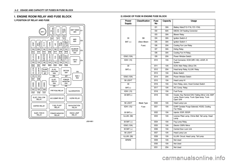
1. ENGINE ROOM RELAY AND FUSE BLOCK
1) POSITION OF RELAY AND FUSE
2) USAGE OF FUSE IN ENGINE FUSE BLOCK
Power
Supply
ClassificationFuse
NoCapacityUsage
Ef130ABattery Main(F13~F16, F21~F24)
Ef260AEBCM, Oil Feeding Conenctor
Ef330ABlower Relay
30SBEf430AIgnition Switch–2
BAT (+)(Slow–BlownEf530AIgnition Switch–1
Fuse)Ef620ACooling Fan Low Relay
Ef730ADefog Relay
Ef830ACooling Fan HI Relay
IGN2 (15A)Ef920APower Window Switch
IGN1 (15)Ef1015AFuel Connector, ECM (MR–140), LEGR, EI
System
30Ef1110AECM, Main Relay (Sirius D4)
BAT(+)Ef1225AHead lamp Relay, ILLUM. Relay
Ef1315ABrake Switch
IGN2 (15A)Ef1420APower Window Switch
56 LIGHTEf1515AHead Lamp HI
30Ef1615AHorn Relay, siren, Hood Contact Switch
BAT(+)Ef1710AA/C Comp. Relay
IGN1 (15)Ef1815AFuel Pump
30 BAT(+)Ef1915ACluster, Key Remind S/W, Folding Mirror Unit, MAP
Lamp, Room Lamp, Trunk Open lamp, Trunk
Open S/W
56 LIGHTBlade TypeEf2010AHead Lamp Low
IGN1 (15)/FuseEf2115AEVAP Canister Purge Solenoid, HO2S, Cooling
Fan Relay
30 BAT(+)Ef2215Ainjector, EGR, EEGR
ILLUM. (58)Ef2310ALicense Plate Lamp, Chime Bell, Tail Lamp, Head
Lamp
30 BAT (+)Ef2415AFog Lamp Relay
IGN2 (15A)Ef2510AElectric OSRV Mirror
30 BAT (+)Ef2615ACentral Door Lock Unit
56 LIGHTEf2710AHead Lamp Low
ILLUM. (58)Ef2810AILLUM. Circuit, Head Lamp, Tail Lamp
SPAREEf2910ANot Used
Ef3015ANot Used
Ef3125ANot Used
Page 1955 of 2643
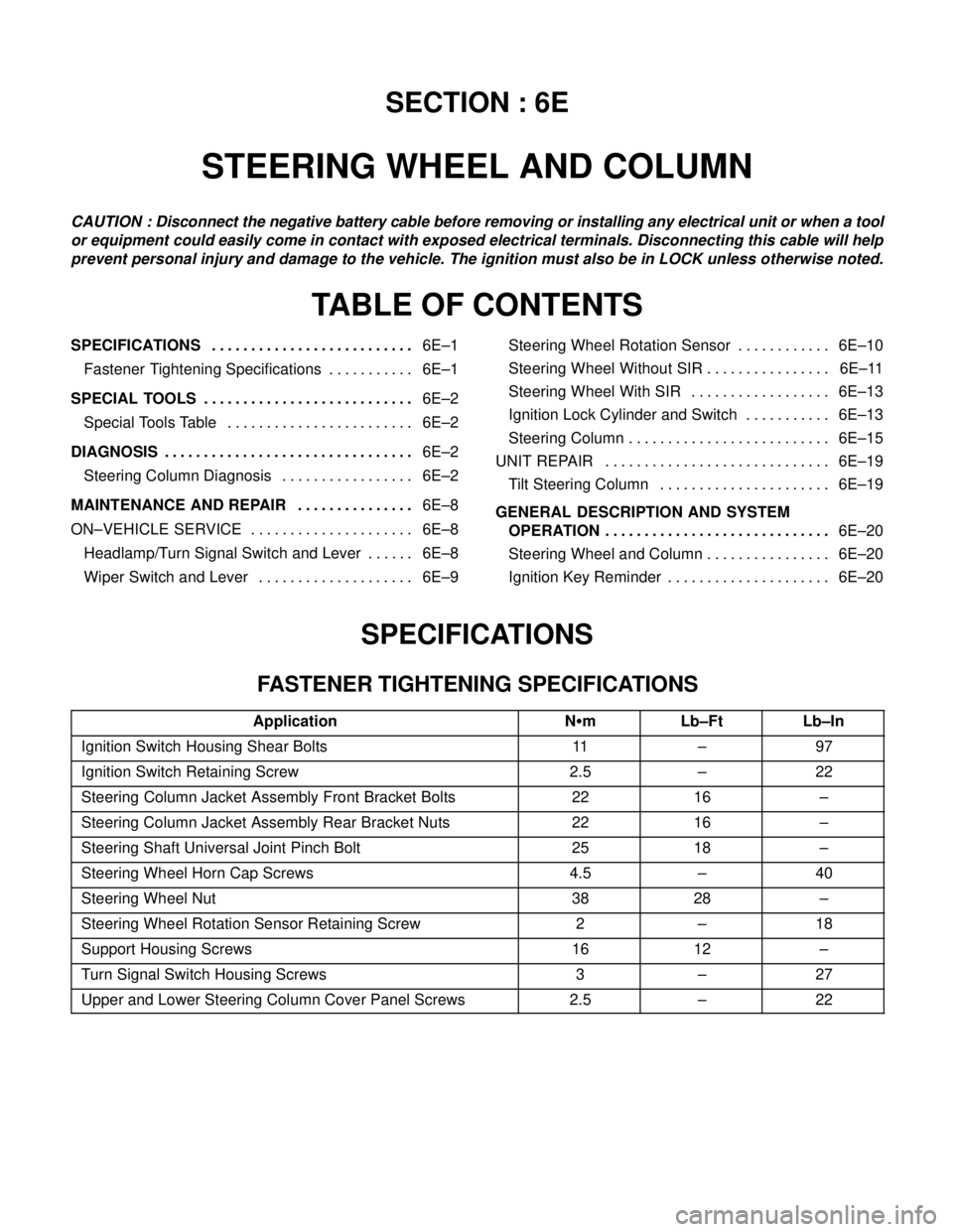
SECTION : 6E
STEERING WHEEL AND COLUMN
CAUTION : Disconnect the negative battery cable before removing or installing any electrical unit or when a tool
or equipment could easily come in contact with exposed electrical terminals. Disconnecting this cable will help
prevent personal injury and damage to the vehicle. The ignition must also be in LOCK unless otherwise noted.
TABLE OF CONTENTS
SPECIFICATIONS6E–1 . . . . . . . . . . . . . . . . . . . . . . . . . .
Fastener Tightening Specifications 6E–1. . . . . . . . . . .
SPECIAL TOOLS6E–2 . . . . . . . . . . . . . . . . . . . . . . . . . . .
Special Tools Table 6E–2. . . . . . . . . . . . . . . . . . . . . . . .
DIAGNOSIS6E–2 . . . . . . . . . . . . . . . . . . . . . . . . . . . . . . . .
Steering Column Diagnosis 6E–2. . . . . . . . . . . . . . . . .
MAINTENANCE AND REPAIR6E–8 . . . . . . . . . . . . . . .
ON–VEHICLE SERVICE 6E–8. . . . . . . . . . . . . . . . . . . . .
Headlamp/Turn Signal Switch and Lever 6E–8. . . . . .
Wiper Switch and Lever 6E–9. . . . . . . . . . . . . . . . . . . . Steering Wheel Rotation Sensor 6E–10. . . . . . . . . . . .
Steering Wheel Without SIR 6E–11. . . . . . . . . . . . . . . .
Steering Wheel With SIR 6E–13. . . . . . . . . . . . . . . . . .
Ignition Lock Cylinder and Switch 6E–13. . . . . . . . . . .
Steering Column 6E–15. . . . . . . . . . . . . . . . . . . . . . . . . .
UNIT REPAIR 6E–19. . . . . . . . . . . . . . . . . . . . . . . . . . . . .
Tilt Steering Column 6E–19. . . . . . . . . . . . . . . . . . . . . .
GENERAL DESCRIPTION AND SYSTEM
OPERATION6E–20 . . . . . . . . . . . . . . . . . . . . . . . . . . . . .
Steering Wheel and Column 6E–20. . . . . . . . . . . . . . . .
Ignition Key Reminder 6E–20. . . . . . . . . . . . . . . . . . . . .
SPECIFICATIONS
FASTENER TIGHTENING SPECIFICATIONS
ApplicationNSmLb–FtLb–In
Ignition Switch Housing Shear Bolts11–97
Ignition Switch Retaining Screw2.5–22
Steering Column Jacket Assembly Front Bracket Bolts2216–
Steering Column Jacket Assembly Rear Bracket Nuts2216–
Steering Shaft Universal Joint Pinch Bolt2518–
Steering Wheel Horn Cap Screws4.5–40
Steering Wheel Nut3828–
Steering Wheel Rotation Sensor Retaining Screw2–18
Support Housing Screws1612–
Turn Signal Switch Housing Screws3–27
Upper and Lower Steering Column Cover Panel Screws2.5–22