2004 DAEWOO LACETTI height
[x] Cancel search: heightPage 945 of 2643

REAR SUSPENSION 2D – 3
DAEWOO V–121 BL4
DIAGNOSIS
EXCESSIVE FRICTION CHECK
Check excessive friction in the rear suspension as follows:
1. With the aid of a helper, lift up on the rear bumper
and raise the vehicle as high as possible. Slowly
release the bumper and allow the car to assume
normal trim height.
2. Measure the distance from the floor to the center of
the bumper.
3. Push down on the bumper, release slowly, and al-
low the car to assume normal trim height.4. Measure the distance from the floor to the center of
the bumper.
The difference between the two measurements should be
less than 12.7 mm (0.50 inch). If the difference exceeds
this limit, inspect the control arms for damage or wear.
STRUT DAMPENER
A strut dampener is basically a shock absorber. However,
strut dampeners are easier to extend and retract by hand
than are shock absorbers.
Struts Seem Weak
ChecksAction
Check the tire pressures.Adjust the tire pressures to the specifications on the tire
placard.
Check the load conditions under which the vehicle is nor-
mally driven.Consult with the owner to confirm the owner’s understand-
ing of normal load conditions.
Check the compression and rebound effectiveness of the
strut dampener.Quickly push down and then lift up on the corner of the
bumper nearest the strut dampener being tested.
Compare the compression and rebound with those of a
similar vehicle that has an acceptable ride quality.
Replace the strut dampener, if needed.
Struts Are Noisy
ChecksAction
Check the mountings for looseness or damage.Tighten the strut dampener. Replace the strut dampener,
if needed.
Check the compression and rebound effectiveness of the
strut dampener.Quickly push down and then lift up on the corner of the
bumper nearest the strut dampener being tested.
Compare the compression and rebound with those of a
similar vehicle that has an acceptable ride quality.
Replace the strut dampener, if needed.
Leaks
ChecksAction
Check for a slight trace of fluid.The strut dampener is OK.
Check the seal cover on the fully extended strut.Replace the strut dampener.
Check for an excessive amount of fluid on the strut damp-
ener.Replace the strut dampener.
Page 1567 of 2643

5A1 – 218IZF 4 HP 16 AUTOMATIC TRANSAXLE
DAEWOO V–121 BL4
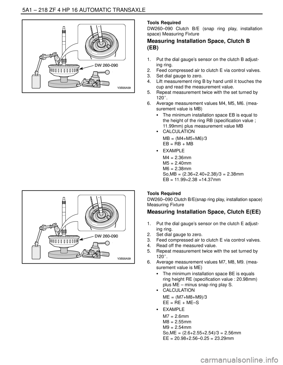
Tools Required
DW260–090 Clutch B/E (snap ring play, installation
space) Measuring Fixture
Measuring Installation Space, Clutch B
(EB)
1. Put the dial gauge’s sensor on the clutch B adjust-
ing ring.
2. Feed compressed air to clutch E via control valves.
3. Set dial gauge to zero.
4. Lift measurement ring B by hand until it touches the
cup and read the measurement value.
5. Repeat measurement twice with the set turned by
120°.
6. Average measurement values M4, M5, M6. (mea-
surement value is MB)
S The minimum installation space EB is equal to
the height of the ring RB (specification value ;
11.99mm) plus measurement value MB
S CALCULATION
MB = (M4+M5+M6)/3
EB = RB + MB
S EXAMPLE
M4 = 2.36mm
M5 = 2.40mm
M6 = 2.38mm
So,MB = (2.36+2.40+2.38)/3 = 2.38mm
EB = 11.99+2.38 =14.37mm
Tools Required
DW260–090 Clutch B/E(snap ring play, installation space)
Measuring Fixture
Measuring Installation Space, Clutch E(EE)
1. Put the dial gauge’s sensor on the clutch E adjust-
ing ring.
2. Set dial gauge to zero.
3. Feed compressed air to clutch E via control valves.
4. Read off the measured value.
5. Repeat measurement twice with the set turned by
120°.
6. Average measurement values M7, M8, M9. (mea-
surement value is ME)
S The minimum installation space BE is equals
ring height RE (specification value : 20.98mm)
plus ME – minus snap ring play S.
S CALCULATION
ME = (M7+M8+M9)/3
EE = RE + ME–S
S EXAMPLE
M7 = 2.6mm
M8 = 2.55mm
M9 = 2.54mm
So,ME = (2.6+2.55+2.54)/3 = 2.56mm
EE = 20.98+2.56–0.25 = 23.29mm
Page 1793 of 2643

AISIN AUTOMATIC TRANSAXLE 5A2 – 203
DAEWOO V–121 BL4
Upper Valve Body Key
MarkRetainerHeight/Width/Thickness mm (in.)
ACheck valve11.5 (0.453) / 5.0 (0.197) / 3.2 (0.126)
BSecondary regulator valve16.0 (0.630) / 5.0 (0.197) / 3.2 (0.126)
CLock up control valve16.0 (0.630) / 5.0 (0.197) / 3.2 (0.126)
DReverse control valve11.5 (0.453) / 5.0 (0.197) / 3.2 (0.126)
Page 1797 of 2643

AISIN AUTOMATIC TRANSAXLE 5A2 – 207
DAEWOO V–121 BL4
Lower Valve Body Key
MarkRetainerHeight/Width/Thickness mm (in.)
A4–3 shift timing valve No.136.0 (1.417) / 5.0 (0.197) / 3.2 (0.126)
BLow modulator valve24.0 (0.945) / 5.0 (0.197) / 3.2 (0.126)
C2–3 shift valve10.0 (0.394) / 5.0 (0.197) / 3.2 (0.126)
D1–2 shift valve10.0 (0.394) / 5.0 (0.197) / 3.2 (0.126)
EPrimary regulator valve9.8 (0.386) / 5.2 (0.205) / 3.2 (0.126)
FLock up relay valve16.0 (0.630) / 5.0 (0.197) / 3.2 (0.126)
GSolenoid modulator valve24.0 (0.945) / 5.0 (0.197) / 3.2 (0.126)
Page 1830 of 2643

5B – 6IFIVE–SPEED MANUAL TRANSAXLE
DAEWOO V–121 BL4
SYMPTOM DIAGNOSIS
ChecksAction
Check for a knock at low speeds.S Replace any worn drive axle CV joints.
S Replace any worn side gear hub.
Check for a noise most pronounced on turns.S Correct any abnormalities in the differential gear.
Check for a clunk upon acceleration or deceleration.S Tighten any loose engine mounts.
S Replace any worn drive axle inboard joints.
S Replace any worn differential pinion shaft in the
case.
S Replace any worn side gear hub in the case.
Check for a clunking noise in turns.S Replace any worn outboard CV joint.
Check for a vibration.S Replace any rough wheel bearing.
S Replace any bent drive axle shaft.
S Replace any out–of–round tires.
S Balance any unbalanced tire.
S Replace any worn CV joint in the drive axle shaft.
S Correct an excessive drive axle angle by adjusting
the trim height.
Check for a noise in the NEUTRAL gear with the engine
running.S Replace any worn cluster bearing shaft.
S Replace any worn clutch–release bearing.
S Replace any worn input shaft cluster gears.
S Replace any worn first–gear/bearing.
S Replace any worn second–gear/bearing.
S Replace any worn third–gear/bearing.
S Replace any worn fourth–gear/bearing.
S Replace any worn fifth–gear/bearing.
S Replace any worn mainshaft bearings.
Check for a noise in the first gear (1) only.S Replace any chipped, scored, or worn first–gear
constant mesh gears.
S Replace any worn first–second gear synchronizer.
S Replace any worn first–gear/bearing.
S Replace any worn differential–gear/bearing.
S Replace any worn–ring gear.
S Adjust, repair, or replace the shift lever and the rods.
Check for a noise in the second gear (2) only.S Replace any chipped, scored, or worn second–gear
constant mesh gears.
S Replace any worn first–second gear synchronizer.
S Replace any worn second–gear/bearing.
S Replace any worn differential–gear/bearing.
S Replace any worn–ring gear.
S Adjust, repair, or replace the shift lever and the rods.
Check for a noise in the third gear (3) only.S Replace any chipped, scored, or worn third–gear
constant mesh gears.
S Replace any worn third–fourth gear synchronizer.
S Replace any worn third–gear/bearing.
S Replace any worn differential–gear/bearing.
S Replace any worn–ring gear.
S Adjust, repair, or replace the shift lever and the rods.
Page 1895 of 2643

5C – 8ICLUTCH
DAEWOO V–121 BL4
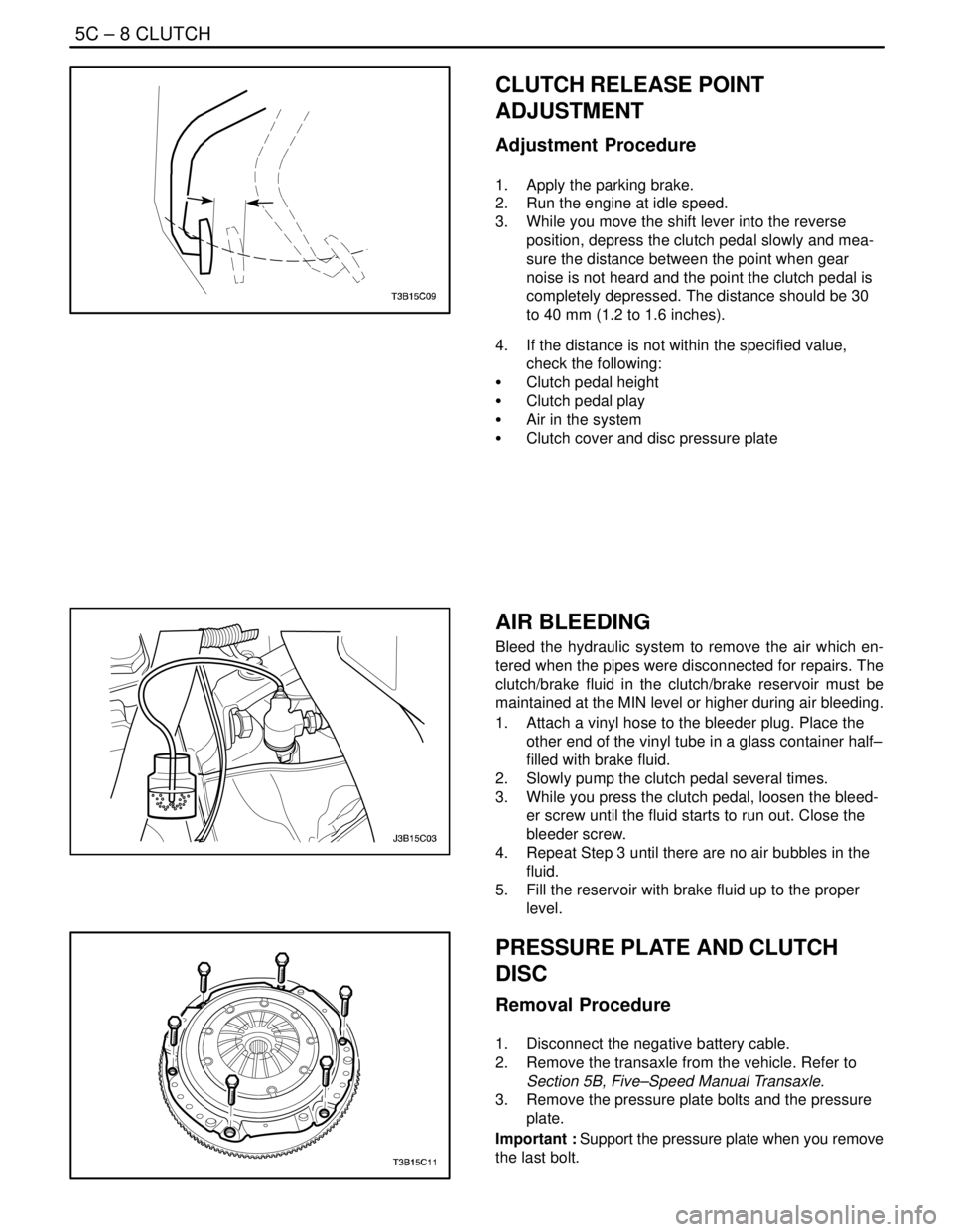
CLUTCH RELEASE POINT
ADJUSTMENT
Adjustment Procedure
1. Apply the parking brake.
2. Run the engine at idle speed.
3. While you move the shift lever into the reverse
position, depress the clutch pedal slowly and mea-
sure the distance between the point when gear
noise is not heard and the point the clutch pedal is
completely depressed. The distance should be 30
to 40 mm (1.2 to 1.6 inches).
4. If the distance is not within the specified value,
check the following:
S Clutch pedal height
S Clutch pedal play
S Air in the system
S Clutch cover and disc pressure plate
AIR BLEEDING
Bleed the hydraulic system to remove the air which en-
tered when the pipes were disconnected for repairs. The
clutch/brake fluid in the clutch/brake reservoir must be
maintained at the MIN level or higher during air bleeding.
1. Attach a vinyl hose to the bleeder plug. Place the
other end of the vinyl tube in a glass container half–
filled with brake fluid.
2. Slowly pump the clutch pedal several times.
3. While you press the clutch pedal, loosen the bleed-
er screw until the fluid starts to run out. Close the
bleeder screw.
4. Repeat Step 3 until there are no air bubbles in the
fluid.
5. Fill the reservoir with brake fluid up to the proper
level.
PRESSURE PLATE AND CLUTCH
DISC
Removal Procedure
1. Disconnect the negative battery cable.
2. Remove the transaxle from the vehicle. Refer to
Section 5B, Five–Speed Manual Transaxle.
3. Remove the pressure plate bolts and the pressure
plate.
Important : Support the pressure plate when you remove
the last bolt.
Page 2096 of 2643

SECTION : 8A
SEAT BELTS
CAUTION : Disconnect the negative battery cable before removing or installing any electrical unit or when a tool
or equipment could easily come in contact with exposed electrical terminals. Disconnecting this cable will help
prevent personal injury and damage to the vehicle. The ignition must also be in LOCK unless otherwise noted.
TABLE OF CONTENTS
SPECIFICATIONS8A–1 . . . . . . . . . . . . . . . . . . . . . . . . . .
Fastener Tightening Specifications 8A–1. . . . . . . . . . .
SCHEMATIC AND ROUTING DIAGRAMS8A–2 . . . . .
Driver Seat Belt Warning 8A–2. . . . . . . . . . . . . . . . . . . .
DIAGNOSIS8A–3 . . . . . . . . . . . . . . . . . . . . . . . . . . . . . . . .
Driver Seat Belt Warning 8A–3. . . . . . . . . . . . . . . . . . . .
MAINTENANCE AND REPAIR8A–4 . . . . . . . . . . . . . . .
ON–VEHICLE SERVICE 8A–4. . . . . . . . . . . . . . . . . . . . .
Pretensioner Front Seat Belt 8A–4. . . . . . . . . . . . . . . .
Front Seat Belt Height Adjuster 8A–5. . . . . . . . . . . . . . Three–Point Rear Seat Belt (LH,CENTER, RH) 8A–6
Front Seat Belt Buckle 8A–7. . . . . . . . . . . . . . . . . . . . .
GENERAL DESCRIPTION AND SYSTEM
OPERATION 8A–9 . . . . . . . . . . . . . . . . . . . . . . . . . . . . .
Driver Seat Belt Warning 8A–9. . . . . . . . . . . . . . . . . . . .
Three–Point ELR Front Seat Belt With
Pretensioner 8A–9. . . . . . . . . . . . . . . . . . . . . . . . . . . .
Three–Point CLR (ELR) Rear Outboard Seat
Belt 8A–9. . . . . . . . . . . . . . . . . . . . . . . . . . . . . . . . . . . .
Operational and Functional Checks 8A–9. . . . . . . . . .
Child Seat Tether Anchor 8A–9. . . . . . . . . . . . . . . . . . .
SPECIFICATIONS
FASTENER TIGHTENING SPECIFICATIONS
ApplicationNSmLb–FtLb–In
Child Seat Tether Anchor Bolt2518–
Front Seat Belt Height Adjuster Bolts2317–
Seat Belt Anchor Bolt3828–
Seat Belt Retractor Bracket Screws3–27
Seat Belt Retractor Bolt3828–
Page 2100 of 2643

SEAT BELTS 8A – 5
DAEWOO V–121 BL4
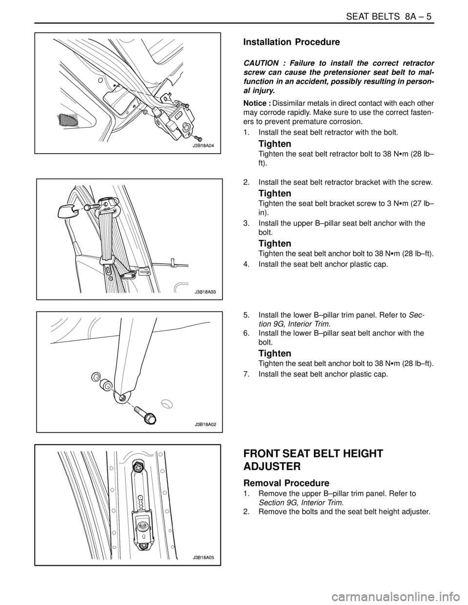
Installation Procedure
CAUTION : Failure to install the correct retractor
screw can cause the pretensioner seat belt to mal-
function in an accident, possibly resulting in person-
al injury.
Notice : Dissimilar metals in direct contact with each other
may corrode rapidly. Make sure to use the correct fasten-
ers to prevent premature corrosion.
1. Install the seat belt retractor with the bolt.
Tighten
Tighten the seat belt retractor bolt to 38 NSm (28 lb–
ft).
2. Install the seat belt retractor bracket with the screw.
Tighten
Tighten the seat belt bracket screw to 3 NSm (27 lb–
in).
3. Install the upper B–pillar seat belt anchor with the
bolt.
Tighten
Tighten the seat belt anchor bolt to 38 NSm (28 lb–ft).
4. Install the seat belt anchor plastic cap.
5. Install the lower B–pillar trim panel. Refer to Sec-
tion 9G, Interior Trim.
6. Install the lower B–pillar seat belt anchor with the
bolt.
Tighten
Tighten the seat belt anchor bolt to 38 NSm (28 lb–ft).
7. Install the seat belt anchor plastic cap.
FRONT SEAT BELT HEIGHT
ADJUSTER
Removal Procedure
1. Remove the upper B–pillar trim panel. Refer to
Section 9G, Interior Trim.
2. Remove the bolts and the seat belt height adjuster.