2004 DAEWOO LACETTI height
[x] Cancel search: heightPage 2101 of 2643

8A – 6ISEAT BELTS
DAEWOO V–121 BL4
Installation Procedure
Notice : Dissimilar metals in direct contact with each other
may corrode rapidly. Make sure to use the correct fasten-
ers to prevent premature corrosion.
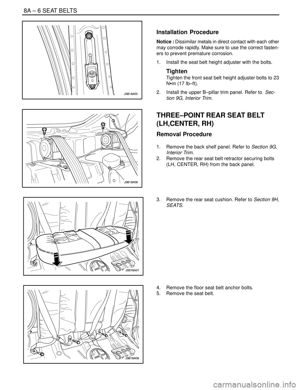
1. Install the seat belt height adjuster with the bolts.
Tighten
Tighten the front seat belt height adjuster bolts to 23
NSm (17 lb–ft).
2. Install the upper B–pillar trim panel. Refer to Sec-
tion 9G, Interior Trim.
THREE–POINT REAR SEAT BELT
(LH,CENTER, RH)
Removal Procedure
1. Remove the back shelf panel. Refer to Section 9G,
Interior Trim.
2. Remove the rear seat belt retractor securing bolts
(LH, CENTER, RH) from the back panel.
3. Remove the rear seat cushion. Refer to Section 9H,
SEATS.
4. Remove the floor seat belt anchor bolts.
5. Remove the seat belt.
Page 2193 of 2643

SUPPLEMENTAL INFLATABLE RESTRAINTS (SIR) 8B – 89
DAEWOO V–121 BL4
HANDLING, INSTALLATION AND
DIAGNOSIS
S Airbag modules should not be subjected to temper-
ature above 65 degrees Celsius(149 degrees Fahr-
enheit).
S An airbag and SDM should not be used if it has
been dropped from height of 0.9 meters(3 feet) or
greater.
S When an SDM is replaced, it must be oriented with
the arrow on the SDM pointing toward the front of
the vehicle.
S It is very important for the SDM to be installed flat
on the mounting surface, parallel to the vehicle’s
longitudinal axis.
S To avoid setting diagnostic trouble codes(DTCs), do
not apply power to the SIR unless all components
are connected or a diagnostic chart request it.
S The SIR Diagnostic System Check must be the
starting point of any SIR diagnostics. The SIR Diag-
nostic System Check will verify proper airbag indi-
cator operation and will lead you to correct chart to
diagnose any SIR malfunctions. Bypassing these
procedures may result in extended diagnostic time
incorrect parts replacement.
REPAIRS AND INSPECTIONS
REQUIRED AFTER AN ACCIDENT
CAUTION : Any repairs to the vehicle’s structure
must return it to the original production configu-
ration. Deployment requires replacement of
SDM, the inflator modules and a dimensional in-
spection of the steering column.
S If any SIR components are damaged, they must be
replaced. If SIR components mounting points are
damaged, they must be repaired or replaced.
S Never use SIR parts from another vehicle. This
does not include remanufactured parts purchased
from an authorized source.
S Do not attempt to service the SDM, the clock spring
or other airbag modules, these items must be re-
placed if they are defective.
S Verify the part number of replaced airbag modules.
Some inflator modules look identical but contain
different internal components.
Page 2357 of 2643

SECTION : 9H
SEATS
CAUTION : Disconnect the negative battery cable before removing or installing any electrical unit or when a tool
or equipment could easily come in contact with exposed electrical terminals. Disconnecting this cable will help
prevent personal injury and damage to the vehicle. The ignition must also be in LOCK unless otherwise noted.
TABLE OF CONTENTS
SPECIFICATIONS9H–2 . . . . . . . . . . . . . . . . . . . . . . . . . .
Fastener Tightening Specifications 9H–2. . . . . . . . . . .
MAINTENANCE AND REPAIR9H–3 . . . . . . . . . . . . . . .
ON–VEHICLE SERVICE 9H–3. . . . . . . . . . . . . . . . . . . . .
Front Bucket Seat 9H–3. . . . . . . . . . . . . . . . . . . . . . . . .
Front Seatback 9H–4. . . . . . . . . . . . . . . . . . . . . . . . . . . .
Front Seat Cushion 9H–5. . . . . . . . . . . . . . . . . . . . . . . .
Lumbar Support Lever 9H–5. . . . . . . . . . . . . . . . . . . . . .
Height Adjustment Knobs 9H–6. . . . . . . . . . . . . . . . . . .
Front Seat Trim 9H–6. . . . . . . . . . . . . . . . . . . . . . . . . . . . Head Restraint 9H–7. . . . . . . . . . . . . . . . . . . . . . . . . . . .
Rear Seat Cushion 9H–8. . . . . . . . . . . . . . . . . . . . . . . . .
Split Rear Seatback 9H–8. . . . . . . . . . . . . . . . . . . . . . . .
Split Rear Seatback Hinge 9H–9. . . . . . . . . . . . . . . . . .
Rear Seat Center Armrest 9H–9. . . . . . . . . . . . . . . . . .
Seat Covers 9H–10. . . . . . . . . . . . . . . . . . . . . . . . . . . . .
Child Seat Anchorage 9H–10. . . . . . . . . . . . . . . . . . . . .
Hatchback Child Seat Anchorage 9H–11. . . . . . . . . . .
GENERAL DESCRIPTION AND SYSTEM
OPERATION9H–12 . . . . . . . . . . . . . . . . . . . . . . . . . . . . .
Seats 9H–12. . . . . . . . . . . . . . . . . . . . . . . . . . . . . . . . . . .
Page 2362 of 2643

9H – 6ISEATS
DAEWOO V–121 BL4
Installation Procedure
Notice : Dissimilar metals in direct contact with each other
may corrode rapidly. Make sure to use the correct fasten-
ers to prevent premature corrosion.
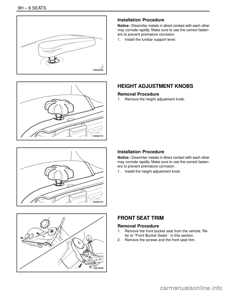
1. Install the lumbar support lever.
HEIGHT ADJUSTMENT KNOBS
Removal Procedure
1. Remove the height adjustment knob.
Installation Procedure
Notice : Dissimilar metals in direct contact with each other
may corrode rapidly. Make sure to use the correct fasten-
ers to prevent premature corrosion.
1. Install the height adjustment knob.
FRONT SEAT TRIM
Removal Procedure
1. Remove the front bucket seat from the vehicle. Re-
fer to ”Front Bucket Seats” in this section.
2. Remove the screws and the front seat trim.
Page 2368 of 2643

9H – 12ISEATS
DAEWOO V–121 BL4
GENERAL DESCRIPTION
AND SYSTEM OPERATION
SEATS
Do not attempt to change the designed seat position by al-
tering the designed seat adjuster–to–floor pan anchor pro-
visions or the seat adjuster–to–seat frame anchor provi-
sions. Changing the seat position could affect the
performance of the seat system.This vehicle is equipped with front bucket seats with sepa-
rate, adjustable head restraints, and a three–passenger
rear bench seat with an optional split folding rear seat. The
front bucket seats also have a recline, a height, and a lum-
bar adjustment. A power driver seat is optional. Seat cush-
ions and seatbacks have formed foam pads, which fit the
contours of the full panel seatback frame assembly and
the designed contour of the seat cushion frame.
Page 2369 of 2643

SECTION : 9I
WATERLEAKS
TABLE OF CONTENTS
SPECIFICATIONS9I–1 . . . . . . . . . . . . . . . . . . . . . . . . . . .
Recommended Materials for Waterleak Repairs 9I–1.
Watertest Stand Specifications 9I–1. . . . . . . . . . . . . . .
DIAGNOSIS9I–2 . . . . . . . . . . . . . . . . . . . . . . . . . . . . . . . . . Waterleak Diagnosis 9I–2. . . . . . . . . . . . . . . . . . . . . . . .
MAINTENANCE AND REPAIR9I–5 . . . . . . . . . . . . . . . .
ON–VEHICLE SERVICE 9I–5. . . . . . . . . . . . . . . . . . . . . .
Waterleak Repair 9I–5. . . . . . . . . . . . . . . . . . . . . . . . . . .
SPECIFICATIONS
RECOMMENDED MATERIALS FOR WATERLEAK
REPAIRS
Leak Areas Repair Materials
Windshield, back windowUrethane adhesive, caulking kit, or the equivalent
Metal jointsBrushable seam sealer which can be painted
Ventilation ducts3Mnv Auto Bedding and Glazing Compound or the equiva-
lent
Small cracks and pin holes3Mnv Drip–Check Sealer or the equivalent
Large holes3Mnv Automotive Joint and Seam Sealer
Weatherstrips3Mnv 08011 Weatherstrip Adhesive or the equivalent
Bolts, studs, and screwsStrip caulk
WATERTEST STAND SPECIFICATIONS
ApplicationDescription
Nozzle TypeFull jet spray nozzle #1/2 GG–25 or equivalent with a 60°
included angle
Nozzle HeightApproximately 1 600 mm (63.0 in.) from the floor
Volume of Flow14L (3.7 gal) per minute
Pressure155 kPa (22.5 psi) measured at the nozzle
Windshield and A–Pillar Test Stand PositionApproximately 30° down, 45° toward the rear, and aimed
at the corner of the windshield
B–Pillar Test Stand PositionApproximately 30° down, 45° toward the rear, and aimed
at the center of the rear door
Back Window and Rear Deck Lid Test Stand PositionApproximately 30° down, 30° toward the front and aimed
approximately 610 mm (24.0 in.) from the corner of the
back window
Page 2370 of 2643

9I – 2IWATERLEAKS
DAEWOO V–121 BL4
DIAGNOSIS
WATERLEAK DIAGNOSIS
The repair of waterleaks in the body requires proper test-
ing and diagnosis. Repair waterleaks by adjusting the mis-
aligned parts and using the proper repair materials. First,
determine what conditions cause the leak. For example,
the leak may occur only when the vehicle is parked on an
incline, or water may appear only in the spare tire compart-
ment. Second, test the area for the source of the leak us-
ing the following testing methods. If the general leak area
is found, determine the exact entry point of the leak by us-
ing a water hose or an air hose. If the general leak area is
not obvious, use the watertest stands to determine the
area of the leak. It may be necessary to remove some inte-
rior trim panels or some parts in order to locate the leaks.
Important : It is necessary to find the origin of all the leaks
before making any repairs. Random repairs may stop the
leak only temporarily and may make future repairs more
difficult. Continue localized testing in the general area in
order to ensure that all leaks are found.
Generalized Testing
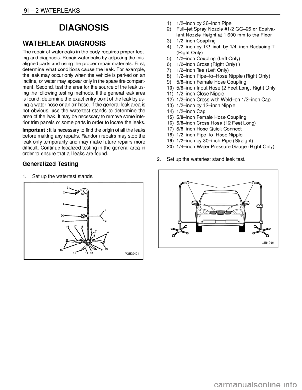
1. Set up the watertest stands.
1) 1/2–inch by 36–inch Pipe
2) Full–jet Spray Nozzle #1/2 GG–25 or Equiva-
lent Nozzle Height at 1,600 mm to the Floor
3) 1/2–inch Coupling
4) 1/2–inch by 1/2–inch by 1/4–inch Reducing T
(Right Only)
5) 1/2–inch Coupling (Left Only)
6) 1/2–inch Cross (Right Only) )
7) 1/2–inch Tee (Left Only)
8) 1/2–inch Pipe–to–Hose Nipple (Right Only)
9) 5/8–inch Female Hose Coupling
10) 5/8–inch Input Hose (2 Feet Long, Right Only
11) 1/2–inch Close Nipple
12) 1/2–inch Cross with Weld–on 1/2–inch Cap
13) 1/2–inch by 12–inch Nipple
14) 1/2–inch Cap
15) 5/8–inch Female Hose Coupling
16) 5/8–inch Cross Hose (12 Feet Long)
17) 5/8–inch Hose Quick Connect
18) 1/2–inch Pipe–to–Hose Nipple
19) 1/2–inch by 30–inch Pipe (Straight)
20) 1/4–inch Water Pressure Gauge (Right Only)
2. Set up the watertest stand leak test.