Page 2254 of 2643

9B – 28ILIGHTING SYSTEMS
DAEWOO V–121 BL4
Turn Signal Lamps and Hazard Lamps Do Not Work
StepActionValue(s)YesNo
1Check fuses F3 and F14.
Is either fuse blown?–Go to Step 2Go to Step 3
21. Check for a short circuit and repair it, if neces-
sary.
2. Replace the fuse.
Is the repair complete?–System OK–
31. Turn the ignition ON.
2. Check the voltage at fuses F3 and F14.
Does the battery voltage available at both fuses F3
and F14 equal the specified value?11–14 vGo to Step 4Go to Step 7
41. Turn the hazard switch on.
2. Remove each of the inoperative lamps from its
socket.
3. Test each lamp socket positive terminal with a
voltmeter.
Does the battery voltage pulsing at the turn signal
hazard lamp socket positive terminal equal the spe-
cified value?11–14 vGo to Step 5Go to Step 9
5At each bulb socket, use an ohmmeter to check the
ground circuit.
Is the resistance equal to the specified value?� 0 WGo to Step 6Go to Step 8
6Replace any faulty turn signal/hazard bulbs.
Is the repair complete?–System OK–
7Repair the power supply circuit to fuses.
Is the repair complete?–System OK–
8Repair the open ground wires.
Is the repair complete?–System OK–
91. Turn on the hazard lamp switch.
2. Test the blinker unit connector terminal 49a
with a voltmeter.
Does the battery voltage pulsing at the blinker unit
terminal 49a equal the specified value?11–14 vGo to Step 15Go to Step 10
101. Turn on the hazard lamp switch.
2. Test the blinker unit connector terminal 49 with
a voltmeter.
Does the battery voltage available at the blinker unit
terminal 49 equal the specified value?11–14 vGo to Step 11Go to Step 14
111. Disconnect the blinker unit from the connector.
2. Use an ohmmeter to check between ground
and the connector for terminal 31 of the blinker
unit.
Is the resistance equal to the specified value?� 0 WGo to Step 13Go to Step 12
12Repair the blinker unit ground connection.
Is the repair complete?–System OK–
13Replace the faulty blinker unit.
Is the repair complete?–System OK–
Page 2257 of 2643

LIGHTING SYSTEMS 9B – 31
DAEWOO V–121 BL4
INTERIOR COURTESY AND LUGGAGE COMPARTMENT
LAMPS
Interior Courtesy Lamp Inoperative
CAUTION : Always make sure there is an electrical
load (lamp bulb, etc.) in any circuit between battery
terminals. Do not make a short circuit between bat-
tery terminals with a jumper wire. Hazardous spark-
ing would result and could cause injury.
Test Description
The number(s) below refer to step(s) on the diagnostictable.
1. Bulb test. Clip one end of a jumper wire to the neg-
ative battery terminal. Clip the other end of the
jumper wire onto one end of the bulb. Take the free
end of the bulb (the end without the jumper at-
tached) and touch it to the positive battery terminal.
Step
ActionValue(s)YesNo
11. Remove the interior courtesy lamp bulb and
inspect the filament.
2. If the filament is not broken, test the bulb using
the vehicle’s battery and a jumper wire.
Does the bulb pass the visual and physical checks?–Go to Step 3Go to Step 2
2Replace the bulb.
Is the repair complete?–System OK–
31. Reinstall the interior courtesy lamp bulb.
2. Check fuse Ef19.
Is fuse Ef19 blown?–Go to Step 4Go to Step 5
41. Check for a short circuit and repair it, if neces-
sary.
2. Replace the fuse.
Is the repair complete?–System OK–
5Check fuse Ef19.
Does the voltage at fuse Ef19 equal the specified
value?11–14 vGo to Step 7Go to Step 6
6Repair the open power supply circuit for fuse Ef19.
Is the repair complete?–System OK–
71. Disconnect the interior courtesy lamp electrical
connector.
2. Check the voltage at connector terminal 1.
Does the voltage at connector terminal 1 equal the
value specified?11–14 vGo to Step 8Go to Step 9
8Repair the open circuit between fuse Ef19 and the
interior courtesy lamp terminal 1.
Is the repair complete?–System OK–
91. With the interior courtesy lamp disconnected,
turn it to the on position.
2. Use an ohmmeter to check the resistance be-
tween ground and terminal 2 of the interior
courtesy lamp connector (harness side).
Is the resistance equal to the specified value?0WGo to Step 10Go to Step 11
10Replace the interior courtesy lamp switch assembly.
Is the repair complete?–System OK–
11Repair the ground circuit for the interior courtesy
lamp.
Is the repair complete?–System OK–
Page 2258 of 2643

9B – 32ILIGHTING SYSTEMS
DAEWOO V–121 BL4
Luggage Compartment Lamp Inoperative
CAUTION : Always make sure there is an electrical
load (lamp bulb, etc.) in any circuit between battery
terminals. Do not make a short circuit between bat-
tery terminals with a jumper wire. Hazardous spark-
ing would result and could cause injury.
Test Description
The number(s) below refer to step(s) on the diagnostictable.
1. Bulb test. Clip one end of a jumper wire to the neg-
ative battery terminal. Clip the other end of the
jumper wire onto one end of the bulb. Take the free
end of the bulb (the end without the jumper at-
tached) and touch it to the positive battery terminal.
Step
ActionValue(s)YesNo
11. Remove the luggage compartment lamp bulb
and inspect the filament.
2. If the filament is not broken, test the bulb using
the vehicle’s battery and a jumper wire.
Does the bulb pass the visual and physical check?–Go to Step 3Go to Step 2
2Replace the bulb.
Is the repair complete?–System OK–
31. Reinstall the luggage compartment lamp bulb.
2. Check fuse Ef19.
Is fuse Ef19 blown?–Go to Step 4Go to Step 5
41. Check for a short circuit and repair it, if neces-
sary.
2. Replace the fuse.
Is the repair complete?–System OK–
5Check fuse Ef19.
Does the voltage at fuse Ef19 equal the specified
value?11–14 vGo to Step 7Go to Step 6
6Repair the open power supply circuit for fuse Ef19.
Is the repair complete?–System OK–
71. Disconnect the luggage compartment lamp
electrical connector.
2. Check the voltage at the orange wire.
Does the voltage at the ORN wire equal the specified
value?11–14 vGo to Step 8Go to Step 9
8Repair the open circuit between fuse Ef19 and the
luggage compartment lamp.
Is the repair complete?–System OK–
91. Reconnect the luggage compartment lamp.
2. Remove the luggage compartment lamp
switch.
3. With a voltmeter (or test lamp), test the PNK/
BLK wire at the luggage compartment lamp
switch.
Does the voltage at the luggage compartment lamp
switch equal the specified value?11–14 vGo to Step 11Go toStep 10
10Repair the open circuit between the luggage
compartment lamp and the luggage compartment
lamp switch.
Is the repair complete?–System OK–
Page 2261 of 2643
LIGHTING SYSTEMS 9B – 35
DAEWOO V–121 BL4
StepNo Yes Value(s) Action
12Repair the open circuit between the fog lamp relay
terminal 87 and the fog lamps.
Is the repair complete?–System OK–
13Use an ohmmeter (or test lamp) to check the ground
at terminal 1 of the fog lamp connector.
Does the resistance equal the specified value?0 WGo to Step 15Go to Step 14
14Repair the fog lamp ground circuit.
Is the repair complete?–System OK–
15Replace the faulty fog lamp bulbs.
Is the repair complete?–System OK–
Page 2262 of 2643
9B – 36ILITHING SYSTEMS
DAEWOO V–121 BL4
MAINTENANCE AND REPAIR
ON–VEHICLE SERVICE
HEADLAMPS/FRONT TURN SIGNAL
LAMPS
Removal Procedure
1. Disconnect the negative battery cable.
2. Remove the headlamp mounting bolts and nut.
3. Disconnect the electrical connectors.
4. Remove the turn signal bulb.
5. Remove the headlamp assembly.
6. Remove the cap concealing the headlamp bulb.
7. Disconnect the headlamp bulb electrical connector.
8. Remove the headlamp bulb.
Installation Procedure
1. Install the headlamp bulb.
2. Connect the headlamp bulb electrical connector.
3. Install the cap concealing the headlamp bulb.
4. Install the turn signal bulb.
5. Connect the electrical connectors.
Notice : Dissimilar metals in direct contact with each other
may corrode rapidly. Make sure to use the correct fasten-
ers to prevent premature corrosion.
6. Install the headlamp assembly with the bolts and
nut.
7. Connect the negative battery cable.
Page 2265 of 2643
LITHING SYSTEMS 9B – 39
DAEWOO V–121 BL4
4. Remove the fog lamp access cover.
5. Remove the retaining wire.
6. Remove the bulb.
Installation Procedure
1. Install the bulb.
2. Install the retaining wire.
3. Install the fog lamp access cover.
4. Connect the electrical connector.
Notice : Dissimilar metals in direct contact with each other
may corrode rapidly. Make sure to use the correct fasten-
ers to prevent premature corrosion.
5. Install the front fog lamp with the bolts.
Tighten
Tighten the front fog lamp bolts to 4 NSm (35 lb–in).
6. Connect the negative battery cable.
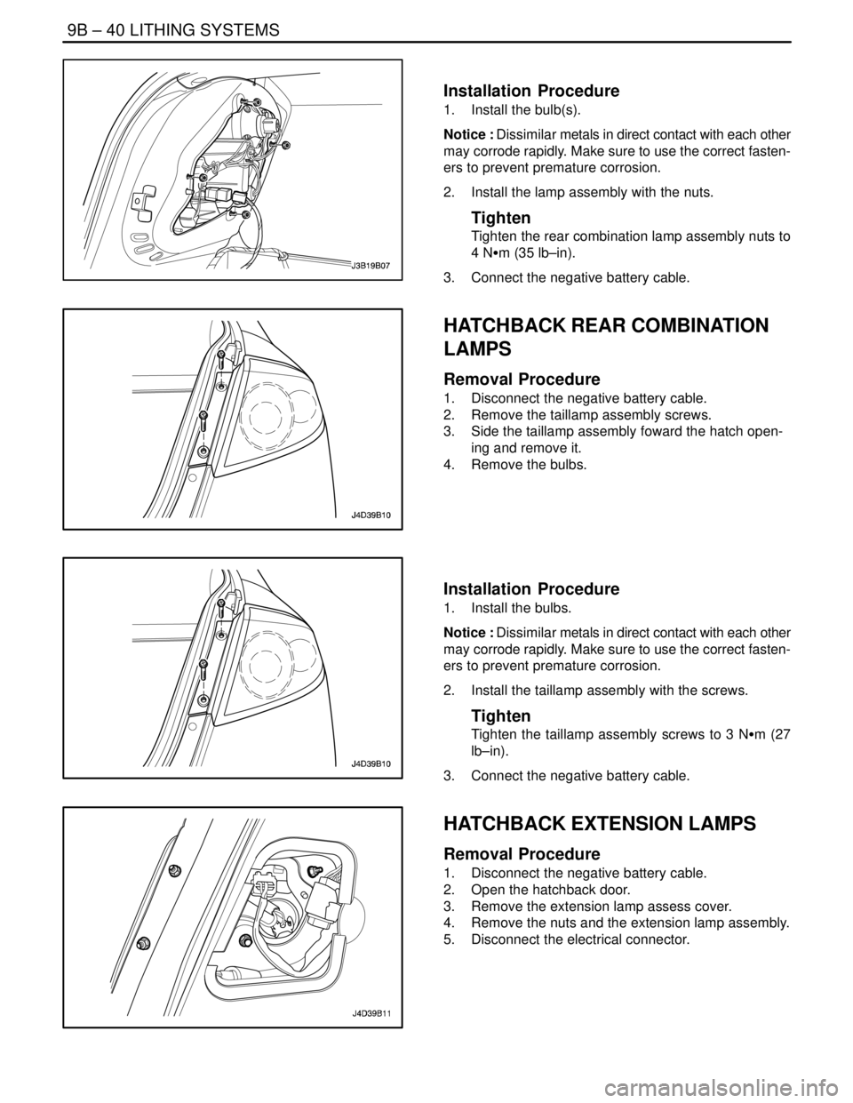
NOTCHBACK REAR COMBINATION
LAMPS
(Typical)
Removal Procedure
1. Disconnect the negative battery cable.
2. Remove the nuts and the lamp assembly.
3. Remove the bulb(s).
Page 2266 of 2643

9B – 40ILITHING SYSTEMS
DAEWOO V–121 BL4
Installation Procedure
1. Install the bulb(s).
Notice : Dissimilar metals in direct contact with each other
may corrode rapidly. Make sure to use the correct fasten-
ers to prevent premature corrosion.
2. Install the lamp assembly with the nuts.
Tighten
Tighten the rear combination lamp assembly nuts to
4 NSm (35 lb–in).
3. Connect the negative battery cable.
HATCHBACK REAR COMBINATION
LAMPS
Removal Procedure
1. Disconnect the negative battery cable.
2. Remove the taillamp assembly screws.
3. Side the taillamp assembly foward the hatch open-
ing and remove it.
4. Remove the bulbs.
Installation Procedure
1. Install the bulbs.
Notice : Dissimilar metals in direct contact with each other
may corrode rapidly. Make sure to use the correct fasten-
ers to prevent premature corrosion.
2. Install the taillamp assembly with the screws.
Tighten
Tighten the taillamp assembly screws to 3 NSm (27
lb–in).
3. Connect the negative battery cable.
HATCHBACK EXTENSION LAMPS
Removal Procedure
1. Disconnect the negative battery cable.
2. Open the hatchback door.
3. Remove the extension lamp assess cover.
4. Remove the nuts and the extension lamp assembly.
5. Disconnect the electrical connector.
Page 2268 of 2643

9B – 42ILITHING SYSTEMS
DAEWOO V–121 BL4
Installation Procedure
Notice : Dissimilar metals in direct contact with each other
may corrode rapidly. Make sure to use the correct fasten-
ers to prevent premature corrosion.
1. Install the CHMSL with the bolts.
Tighten
Tighten the CHMSL mounting bolts to 4 NSm (35 lb–
in).
2. Connect the negative battery cable.
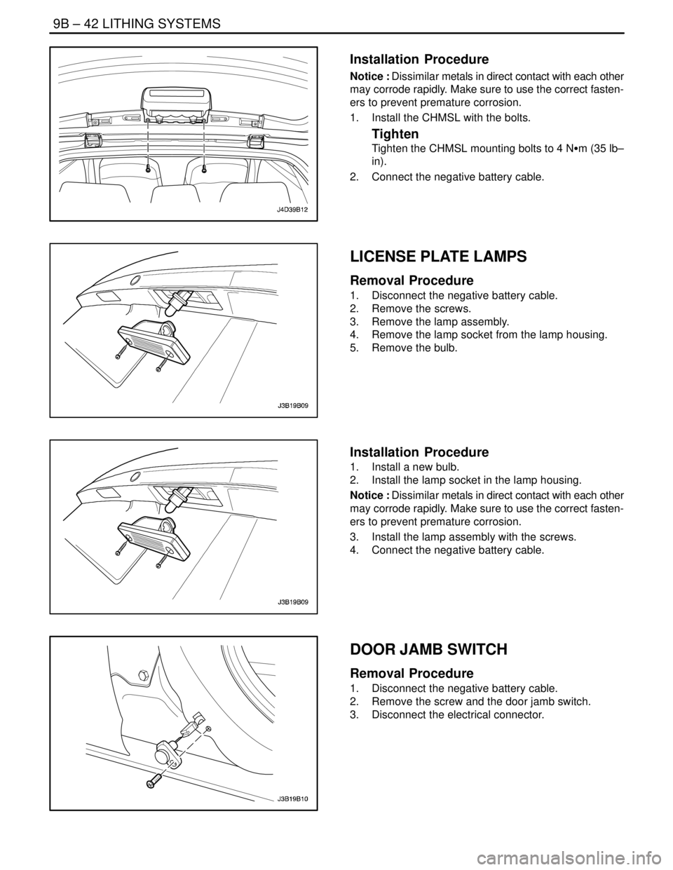
LICENSE PLATE LAMPS
Removal Procedure
1. Disconnect the negative battery cable.
2. Remove the screws.
3. Remove the lamp assembly.
4. Remove the lamp socket from the lamp housing.
5. Remove the bulb.
Installation Procedure
1. Install a new bulb.
2. Install the lamp socket in the lamp housing.
Notice : Dissimilar metals in direct contact with each other
may corrode rapidly. Make sure to use the correct fasten-
ers to prevent premature corrosion.
3. Install the lamp assembly with the screws.
4. Connect the negative battery cable.
DOOR JAMB SWITCH
Removal Procedure
1. Disconnect the negative battery cable.
2. Remove the screw and the door jamb switch.
3. Disconnect the electrical connector.