2004 DAEWOO LACETTI differential
[x] Cancel search: differentialPage 1579 of 2643

5A1 – 230IZF 4 HP 16 AUTOMATIC TRANSAXLE
DAEWOO V–121 BL4
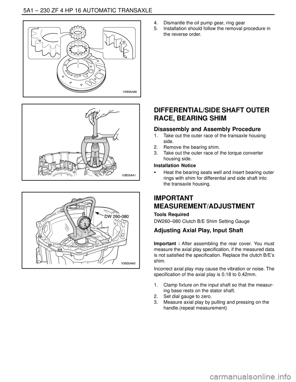
4. Dismantle the oil pump gear, ring gear
5. Installation should follow the removal procedure in
the reverse order.
DIFFERENTIAL/SIDE SHAFT OUTER
RACE, BEARING SHIM
Disassembly and Assembly Procedure
1. Take out the outer race of the transaxle housing
side.
2. Remove the bearing shim.
3. Take out the outer race of the torque converter
housing side.
Installation Notice
S Heat the bearing seats well and insert bearing outer
rings with shim for differential and side shaft into
the transaxle housing.
IMPORTANT
MEASUREMENT/ADJUSTMENT
Tools Required
DW260–080 Clutch B/E Shim Setting Gauge
Adjusting Axial Play, Input Shaft
Important : After assembling the rear cover. You must
measure the axial play specification, if the measured data
is not satisfied the specification. Replace the clutch B/E’s
shim.
Incorrect axial play may cause the vibration or noise. The
specification of the axial play is 0.18 to 0.42mm.
1. Clamp fixture on the input shaft so that the measur-
ing base rests on the stator shaft.
2. Set dial gauge to zero.
3. Measure axial play by pulling and pressing on the
handle.(repeat measurement)
Page 1581 of 2643

5A1 – 232IZF 4 HP 16 AUTOMATIC TRANSAXLE
DAEWOO V–121 BL4
GENERAL DESCRIPTION
AND SYSTEM OPERATION
The ZF 4HP 16 automatic transaxle consists primarily of
the following components.
Mechanical
S Torque converter with TCC
S Drive link assembly
S Two multiple disk clutch assemblies : Clutch B,E
S Three multiple brake assemblies : Brake C,D,F
S Lock–up clutch valve
S Two planetary gear sets
S One oil pump
S Final drive and differential assembly
Electronic
S Two shift solenoid valve(sol.1,2)
S Four pressure control solenoid valve(EDS)
S Two speed sensors : A/T ISS and A/T OSS
S Fluid temperature sensor
S Automatic transaxle control module(TCM)
S Wiring harness assembly
MECHANICAL COMPONENTS
Torque Converter
The converter consists of the impeller, the turbine wheel,
the reaction member (stator) and the oil to transmit torque.
The impeller, which is driven by the engine, causes the oil
in the converter to flow in a circular pattern. This oil flow
meets the turbine wheel, where is direction of flow is de-
flected. At the hub, the oil leaves the turbine and reaches
the reaction member (stator), where it is once again de-
flected so that it reaches the impeller at the correct angle
of flow.
The reversal effect generates movement in the stator, the
reaction torque then amplifies the turbine torque.
The ratio between turbine torque and torque is referred to
as torque multiplication.
The greater the difference is speed between the pump and
turbine, the greater the torque multiplication; it is at its
highest when the turbine is at a standstill. The higher the
speed of the turbine, the lower the torque multiplication.
When the turbine speed reaches about 85%of the pump
speed, torque multiplication=1, i.e. the turbine torque
equivalent to pump torque.
The stator, which bears against the housing via the free-
wheel, is then rotating freely in the oil flow and the free-
wheel is over–come. From this point onwards, the con-
verter acts as a straightforward fluid coupling.
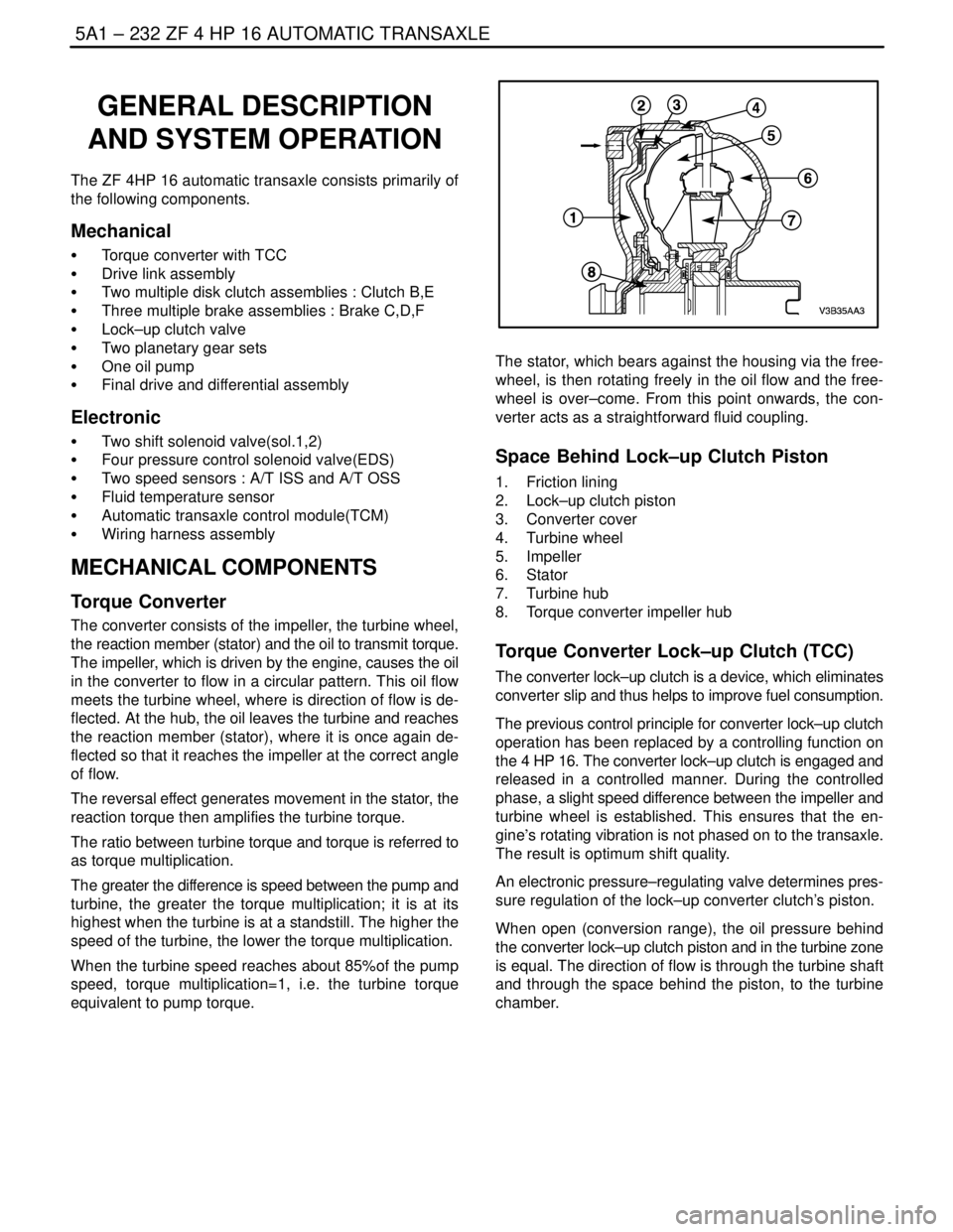
Space Behind Lock–up Clutch Piston
1. Friction lining
2. Lock–up clutch piston
3. Converter cover
4. Turbine wheel
5. Impeller
6. Stator
7. Turbine hub
8. Torque converter impeller hub
Torque Converter Lock–up Clutch (TCC)
The converter lock–up clutch is a device, which eliminates
converter slip and thus helps to improve fuel consumption.
The previous control principle for converter lock–up clutch
operation has been replaced by a controlling function on
the 4 HP 16. The converter lock–up clutch is engaged and
released in a controlled manner. During the controlled
phase, a slight speed difference between the impeller and
turbine wheel is established. This ensures that the en-
gine’s rotating vibration is not phased on to the transaxle.
The result is optimum shift quality.
An electronic pressure–regulating valve determines pres-
sure regulation of the lock–up converter clutch’s piston.
When open (conversion range), the oil pressure behind
the converter lock–up clutch piston and in the turbine zone
is equal. The direction of flow is through the turbine shaft
and through the space behind the piston, to the turbine
chamber.
Page 1585 of 2643

5A1 – 236IZF 4 HP 16 AUTOMATIC TRANSAXLE
DAEWOO V–121 BL4
ELECTRONICAL COMPONENTS
Selector Lever/Program Switch
The driver engages the travel position via the selector le-
ver:
P : Park Position
R : Reverse
N : Neutral
D : Forward Speeds
Park/Neutral Position Switch
The Park/Neutral Position Switch is located on the selec-
tor shaft and informs the TCM of the current selector lever
position P–R–N–D–3–2–1.
The selector lever position is transmitted to the TCM in en-
coded form along 4 lines. The encoding is such that mal-
functions in the connecting lead are identified.
The Park/Neutral Position Switch is located on the selec-
tor shaft, which is connected to the selector lever via a pull
cable. In addition, the Park/Neutral Position Switch con-
trols the starter interlock, the reversing light and the selec-
tor lever position indicator on the instrument panel.
Signal Combination
L1L2L3L4
P00120
R00012
N01200
D1212120
31212012
21201212
10121212
Automatic Transaxle Output Speed Sensor
(A/T OSS)
The vehicle A/T OSS is a magnetic inductive pickup that
relays information relative to vehicle speed to the TCM.
Vehicle speed information is used by the TCM to control
shift timing, line pressure, and TCC (lock–up clutch) apply
and release.
The output speed sensor mounts in the case at the speed
sensor rotor, which is pressed onto the spur gear. An air
gap of 0.1mm~1.3mm(0.004~0.05in) is maintained be-
tween the sensor and the teeth on the spur gear teeth. The
sensor consists of a permanent magnet surrounded by a
coil of wire.
As the differential rotates, an AC signal is generated by the
output speed sensor (OSS).
Automatic Transaxle Input Speed Sensor
(A/T ISS)
The A/T ISS is a magnetic inductive pickup that relays in-
formation relative to transaxle input speed to the TCM.
The TCM uses transaxle input speed information to con-
trol line pressure, TCC apply and release and transaxle
shift patterns. This information is also uses to calculate the
appropriate operating gear ratios and TCC slippage.
The input speed sensor mounts onto piston B that is inside
of valve body.
An air gap of 1.8~2.2mm(0.07~0.086inch) is maintained
between the sensor and the piston B.
The sensor consists of a permanent magnet surrounded
by a coil of wire. As the piston B is driven by the turbine
shaft, an AC signal induced in the input speed sensor.
Higher vehicle speeds induce a higher frequency and volt-
age measurement at the sensor.
Sensor resistance should measure between 825~835
ohms at 20°C (68°F). Sensor can measure from
1,000~8,000HZ.
Page 1592 of 2643

5A2 – 2IAISIN AUTOMATIC TRANSAXLE
DAEWOO V–121 BL4
Shift Control Lever Assembly 5A2–100. . . . . . . . . . . . .
Transmission Range (TR) Switch 5A2–101. . . . . . . . .
Shift Control Cable 5A2–104. . . . . . . . . . . . . . . . . . . . . .
Shift Select Cover 5A2–105. . . . . . . . . . . . . . . . . . . . . .
Input Shaft Speed (ISS) Sensor 5A2–106. . . . . . . . . .
Output Shaft Speed (OSS) Sensor 5A2–107. . . . . . . .
Transmission Control Module (TCM) 5A2–108. . . . . .
Fluid Cooler Inlet Pipes and Hoses 5A2–109. . . . . . . .
Fluid Cooler Outlet Pipes and Hoses 5A2–110. . . . . .
Transaxle Assembly 5A2–111. . . . . . . . . . . . . . . . . . . . .
UNIT REPAIR 5A2–117. . . . . . . . . . . . . . . . . . . . . . . . . . .
Major Component Disassembly 5A2–117. . . . . . . . . . .
Major Component Assembly 5A2–137. . . . . . . . . . . . .
Oil Pump 5A2–167. . . . . . . . . . . . . . . . . . . . . . . . . . . . . . Direct Clutch 5A2–171. . . . . . . . . . . . . . . . . . . . . . . . . . .
Planetary Ring Gear 5A2–178. . . . . . . . . . . . . . . . . . . .
One–Way Clutch 5A2–180. . . . . . . . . . . . . . . . . . . . . . .
Forward and Reverse Clutch 5A2–183. . . . . . . . . . . . .
Counter Driven Gear 5A2–192. . . . . . . . . . . . . . . . . . . .
Valve Body 5A2–195. . . . . . . . . . . . . . . . . . . . . . . . . . . .
Differential Case 5A2–208. . . . . . . . . . . . . . . . . . . . . . . .
GENERAL DESCRIPTION AND SYSTEM
OPERATION5A2–218 . . . . . . . . . . . . . . . . . . . . . . . . . . .
Transaxle Description 5A2–218. . . . . . . . . . . . . . . . . . .
Electronical Components 5A2–218. . . . . . . . . . . . . . . .
Hydraulic Control System 5A2–221. . . . . . . . . . . . . . . .
Automatic Transaxle System 5A2–222. . . . . . . . . . . . .
Page 1593 of 2643

AISIN AUTOMATIC TRANSAXLE 5A2 – 3
DAEWOO V–121 BL4
SPECIFICATIONS
GENERAL SPECIFICATIONS
Definition
1.6 DOHC
Transaxle Fluid TypeISU DEXRON III or ESSO JWS 3309
Transaxle Fluid Capacity5.77L (6.1 qts)
TRANSAXLE GEAR RATIO
GearRatio
1.6 DOHC
First2.875
Second1.568
Third1.000
Fourth0.697
Reverse2.300
Counter1.020
Differential3.750
FLUID CAPACITY
Capacity
1.6 DOHC
Transaxle Fluid (dry fill)5.77L (6.1 qts)
Transaxle Fluid (drain and refill)2.1L (2.2 qts)
Notice : Fluid capacity (drain and refill) could be changed according to the some condition, therefore be sure to check
the fluid using the oil stick guage.
LINE PRESSURE SPECIFICATION
ApplicationIdlingStall
At ”D” range3.9–4.2 kg/cm2 (55–60 psi)11.3–12.5 kg/cm2 (161–178 psi)
At ”R” range6.0–6.9 kg/cm2 (85–98 psi)16.2–18.6 kg/cm2 (230–265 psi)
Page 1594 of 2643

5A2 – 4IAISIN AUTOMATIC TRANSAXLE
DAEWOO V–121 BL4
FASTENER TIGHTENING SPECIFICATIONS
ApplicationNSmLb–FtLb–In
Drain Plug1713–
Control Cable Adjusting Nut8–71
Shift Control Lever Assembly Mounting Bolts8–71
Manual Valve Lever Shaft Nut12–106
Transmission Range (TR) Switch Bolts5.4–48
Input Speed Sensor Retaining Bolt5.4–48
Output Speed Sensor Retaining Bolt7.4–65
TCM Retaining Bolts5–44
Fluid Cooler Inlet Pipe Fitting Nut3526–
Fluid Cooler Inlet Pipe Bolt9–80
Inlet Pipe Union Bolt3526–
Fluid Cooler Rear Outlet Pipe Fitting Nut3526–
Fluid Cooler Rear Outlet Pipe Clip Bolt9–80
Front Outlet Pipe Union Bolt3526–
Lower Transaxle–to–Engine Retaining Bolts (a)7354–
Lower Transaxle–to–Engine Retaining Bolts (b)3123–
Lower Transaxle–to–Engine Retaining Bolts (c)2115–
Upper Transaxle–to–Engine Mounting Bolts7354–
Upper Transaxle Mounting Bracket Bolts6044–
Rear Mounting Bracket Bolts6044–
Damping Block Connection Nut and Bolt8059–
Torque Converter Bolts4543–
Screw Plugs7.4–65
Transaxle Apply Clamp Bolt5.4–48
Oil Reservoir Lock Plate Bolts5.4–48
Transaxle Case Plate Bolt9.8–87
Transaxle Housing Bolts2922–
Manual Detent Spring Bolt9.8–87
Parking Lock Pawl Bracket Bolts7.4–65
Planetary Ring Gear Nut (Standard)9.8–87
Planetary Ring Gear Nut (Maximum)2922–
Transaxle Rear Cover Bolts2518–
Oil Pump Bolts2518–
Valve Body Bolts11–97
Oil Strainer Bolts9.8–87
Oil Pan Bolts7–62
Unions2518–
Stator Shaft Bolts2518–
Shift Solenoid Valve Bolts11–97
Differential Case–to–Differential Ring Gear Bolt10275–
Page 1596 of 2643

5A2 – 6IAISIN AUTOMATIC TRANSAXLE
DAEWOO V–121 BL4
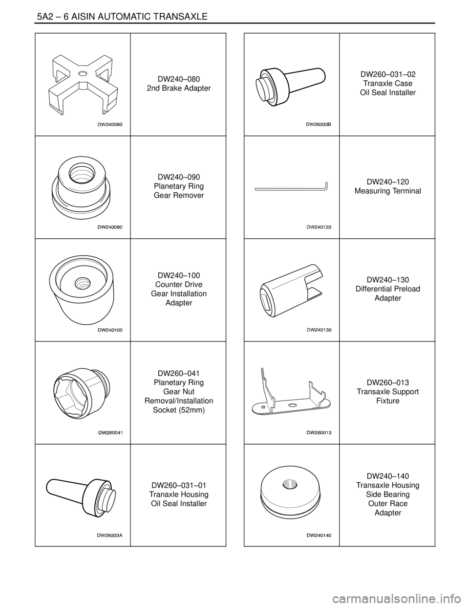
DW240–080
2nd Brake Adapter
DW240–090
Planetary Ring
Gear Remover
DW240–100
Counter Drive
Gear Installation
Adapter
DW260–041
Planetary Ring
Gear Nut
Removal/Installation
Socket (52mm)
DW260–031–01
Tranaxle Housing
Oil Seal Installer
DW260–031–02
Tranaxle Case
Oil Seal Installer
DW240–120
Measuring Terminal
DW240–130
Differential Preload
Adapter
DW260–013
Transaxle Support
Fixture
DW240–140
Transaxle Housing
Side Bearing
Outer Race
Adapter
Page 1610 of 2643

5A2 – 20IAISIN AUTOMATIC TRANSAXLE
DAEWOO V–121 BL4
1. Transaxle Housing
2. Oil Seal
3. Oil Reservoir Plate
4. Transaxle Oil Apply Pipe
5. Differential Gear Oil Apply Pipe
6. Transaxle Oil Apply Pipe Clamp
7. Spring
8. Check Valve Pipe Clamp
9. Apply Gasket
10. Brake Drun Gasket
11. Transaxle Wire
12. O–ring
13. Valve Body
14. Parking Lock Pawl
15. Parking Lock Pawl Shaft
16. Torsion Spring
17. Manual Valve lever Shaft
18. Manual Valve Lever
19. Parking Lock Rod
20. Parking Lock Pawl Bracket
21. Manual Detent Spring
22. Pin
23. Spacer24. Oil Seal
25. Transmission Range (TR) Switch
26. Lock Washer
27. Control Lever
28. Washer
29. Gasket
30. Oil Strainer
31. Oil Pan
32. Gasket
33. Magnet
34. Direct Clutch Accumulator Piston
35. O–ring
36. Spring
37. O–ring
38. Forward Clutch Accumulator Piston
39. O–ring
40. Spring
41. O–ring
42. Overdrive Brake Accumulator Piston
43. O–ring
44. O–ring
45. Spring