2004 DAEWOO LACETTI body front end
[x] Cancel search: body front endPage 157 of 2643
1.8L DOHC ENGINE MECHANICAL 1C2 – 37
DAEWOO V–121 BL4
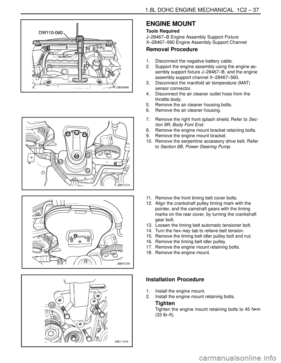
ENGINE MOUNT
Tools Required
J–28467–B Engine Assembly Support Fixture
X–28467–560 Engine Assembly Support Channel
Removal Procedure
1. Disconnect the negative battery cable.
2. Support the engine assembly using the engine as-
sembly support fixture J–28467–B, and the engine
assembly support channel X–28467–560.
3. Disconnect the manifold air temperature (MAT)
sensor connector.
4. Disconnect the air cleaner outlet hose from the
throttle body.
5. Remove the air cleaner housing bolts.
6. Remove the air cleaner housing.
7. Remove the right front splash shield. Refer to Sec-
tion 9R, Body Font End.
8. Remove the engine mount bracket retaining bolts.
9. Remove the engine mount bracket.
10. Remove the serpentine accessory drive belt. Refer
to Section 6B, Power Steering Pump.
11. Remove the front timing belt cover bolts.
12. Align the crankshaft pulley timing mark with the
pointer, and the camshaft gears with the timing
marks on the rear cover, by turning the crankshaft
gear bolt.
13. Loosen the timing belt automatic tensioner bolt.
14. Turn the hex–key tab to relieve belt tension.
15. Remove the timing belt idler pulley bolt and nut.
16. Remove the timing belt idler pulley.
17. Remove the engine mount retaining bolts.
18. Remove the engine mount.
Installation Procedure
1. Install the engine mount.
2. Install the engine mount retaining bolts.
Tighten
Tighten the engine mount retaining bolts to 45 NSm
(33 lb–ft).
Page 166 of 2643

1C2 – 46I1.8L DOHC ENGINE MECHANICAL
DAEWOO V–121 BL4
7. Install the timing belt automatic tensioner and bolt.
8. Install the camshaft gears. Refer to ”Camshaft
Gears” in this section.
9. Install the timing belt and timing belt cover. Refer to
”Timing Belt” in this section.
10. Connect the negative battery cable.
ENGINE
Removal Procedure
1. Remove the fuel pump fuse.
2. Start the engine. After it stalls, crank the engine for
10 seconds to rid the fuel system of fuel pressure.
3. Remove the hood. Refer to Section 9R, Body Front
End.
4. Drain the engine oil.
5. Disconnect the negative battery cable.
6. Discharge the air conditioning (A/C) system, if
equipped. Refer to Section 7B, Manual Control
Heating, Ventilation, and Air Conditioning Systems.
7. Disconnect the manifold air temperature (MAT)
sensor connector.
8. Remove the air cleaner outlet hose from the throttle
body and air cleaner housing.
9. Disconnect the breather tubes from the camshaft
cover.
10. Remove the right front wheel. Refer to Section 2E,
Tires and Wheels.
11. Remove the right front wheel well splash shield.
Refer to Section 9R, Body Font End.
12. Remove the serpentine accessory drive belt. Refer
to Section 6B, Power Steering Pump.
13. Drain the engine coolant. Refer to Section 1D, En-
gine Cooling.
14. Remove the cooling system radiator and the engine
cooling fans. Refer to Section 1D, Engine Cooling.
15. Disconnect the upper radiator hose from the ther-
mostat housing.
16. Disconnect the power steering return hose from the
power steering pump.
17. Disconnect the power steering pressure hose from
the power steering pump.
18. Disconnect the electrical connector at the direct
ignition system (DIS) coil and the electronic control
module (ECM) ground terminal and at the starter
motor.
Page 171 of 2643
1.8L DOHC ENGINE MECHANICAL 1C2 – 51
DAEWOO V–121 BL4
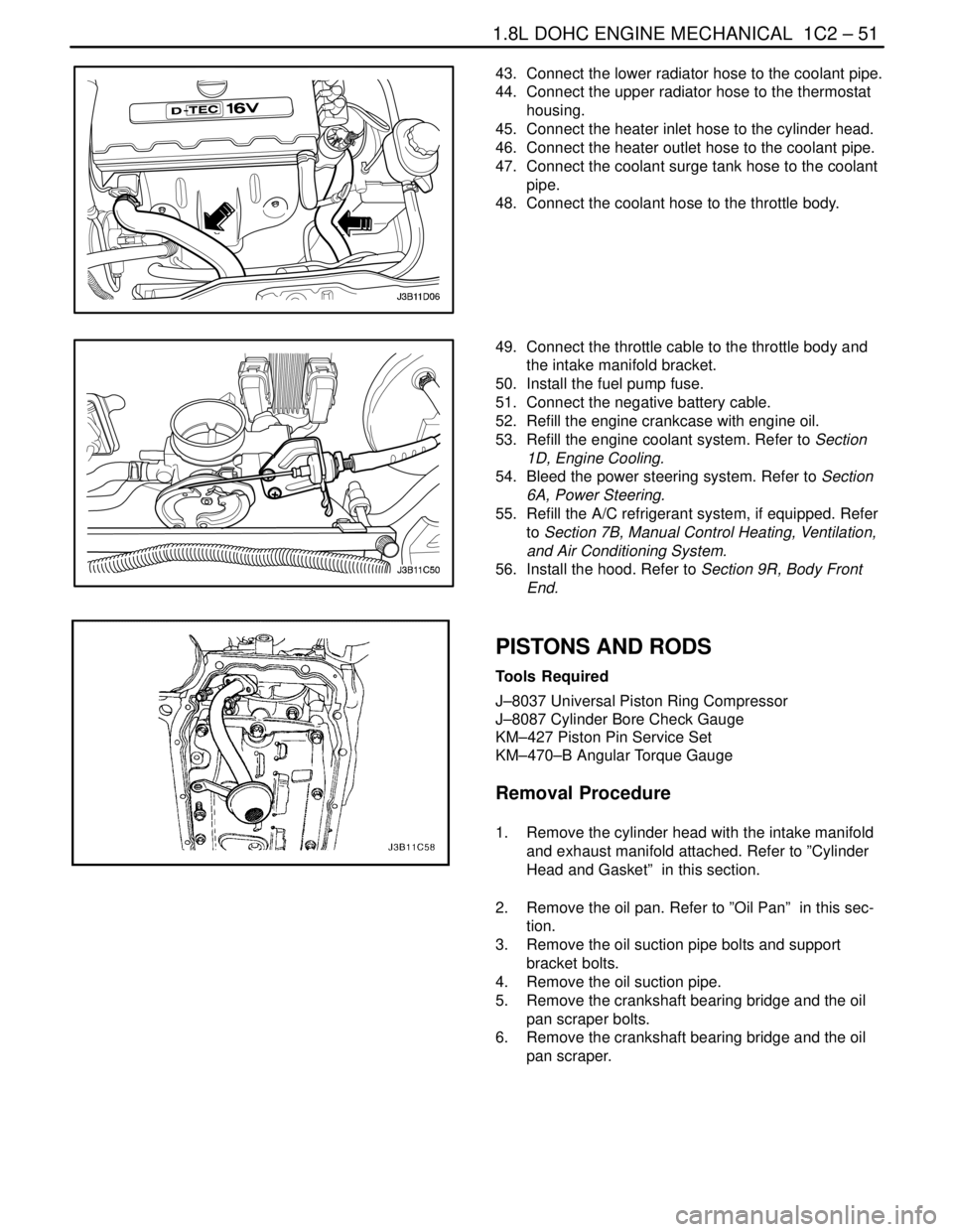
43. Connect the lower radiator hose to the coolant pipe.
44. Connect the upper radiator hose to the thermostat
housing.
45. Connect the heater inlet hose to the cylinder head.
46. Connect the heater outlet hose to the coolant pipe.
47. Connect the coolant surge tank hose to the coolant
pipe.
48. Connect the coolant hose to the throttle body.
49. Connect the throttle cable to the throttle body and
the intake manifold bracket.
50. Install the fuel pump fuse.
51. Connect the negative battery cable.
52. Refill the engine crankcase with engine oil.
53. Refill the engine coolant system. Refer to Section
1D, Engine Cooling.
54. Bleed the power steering system. Refer to Section
6A, Power Steering.
55. Refill the A/C refrigerant system, if equipped. Refer
to Section 7B, Manual Control Heating, Ventilation,
and Air Conditioning System.
56. Install the hood. Refer to Section 9R, Body Front
End.
PISTONS AND RODS
Tools Required
J–8037 Universal Piston Ring Compressor
J–8087 Cylinder Bore Check Gauge
KM–427 Piston Pin Service Set
KM–470–B Angular Torque Gauge
Removal Procedure
1. Remove the cylinder head with the intake manifold
and exhaust manifold attached. Refer to ”Cylinder
Head and Gasket” in this section.
2. Remove the oil pan. Refer to ”Oil Pan” in this sec-
tion.
3. Remove the oil suction pipe bolts and support
bracket bolts.
4. Remove the oil suction pipe.
5. Remove the crankshaft bearing bridge and the oil
pan scraper bolts.
6. Remove the crankshaft bearing bridge and the oil
pan scraper.
Page 869 of 2643

ENGINE CONTROLS 1F – 623
DAEWOO V–121 BL4
GENERAL DESCRIPTION
AND SYSTEM OPERATION
IGNITION SYSTEM OPERATION
This ignition system does not use a conventional distribu-
tor and coil. It uses a crankshaft position sensor input to
the engine control module (ECM). The ECM then deter-
mines Electronic Spark Timing (EST) and triggers the di-
rect ignition system ignition coil.
This type of distributorless ignition system uses a ”waste
spark” method of spark distribution. Each cylinder is
paired with the cylinder that is opposite it (1–4 or 2–3). The
spark occurs simultaneously in the cylinder coming up on
the compression stroke and in the cylinder coming up on
the exhaust stroke. The cylinder on the exhaust stroke re-
quires very little of the available energy to fire the spark
plug. The remaining energy is available to the spark plug
in the cylinder on the compression stroke.
These systems use the EST signal from the ECM to con-
trol the electronic spark timing. The ECM uses the follow-
ing information:
S Engine load (manifold pressure or vacuum).
S Atmospheric (barometric) pressure.
S Engine temperature.
S Intake air temperature.
S Crankshaft position.
S Engine speed (rpm).
ELECTRONIC IGNITION SYSTEM
IGNITION COIL
The Electronic Ignition (EI) system ignition coil provides
the spark for two spark plugs simultaneously. The EI sys-
tem ignition coil is not serviceable and must be replaced
as an assembly.
CRANKSHAFT POSITION SENSOR
This direct ignition system uses a magnetic crankshaft
position sensor. This sensor protrudes through its mount
to within approximately 0.05 inch (1.3 mm) of the crank-
shaft reluctor. The reluctor is a special wheel attached to
the crankshaft or crankshaft pulley with 58 slots machined
into it, 57 of which are equally spaced in 6 degree intervals.
The last slot is wider and serves to generate a ”sync
pulse.” As the crankshaft rotates, the slots in the reluctor
change the magnetic field of the sensor, creating an in-
duced voltage pulse. The longer pulse of the 58th slot
identifies a specific orientation of the crankshaft and al-
lows the engine control module (ECM) to determine the
crankshaft orientation at all times. The ECM uses this in-
formation to generate timed ignition and injection pulses
that it sends to the ignition coils and to the fuel injectors.
CAMAHAFT POSITION SENSOR
The Camshaft Position (CMP) sensor sends a CMP sen-
sor signal to the engine control module (ECM). The ECM
uses this signal as a ”sync pulse” to trigger the injectors in
the proper sequence. The ECM uses the CMP sensor sig-
nal to indicate the position of the #1 piston during its power
stroke. This allows the ECM to calculate true sequential
fuel injection mode of operation. If the ECM detects an in-
correct CMP sensor signal while the engine is running,
DTC P0341 will set. If the CMP sensor signal is lost while
the engine is running, the fuel injection system will shift to
a calculated sequential fuel injection mode based on the
last fuel injection pulse, and the engine will continue to run.
As long as the fault is present, the engine can be restarted.
It will run in the calculated sequential mode with a 1–in–6
chance of the injector sequence being correct.
IDLE AIR SYSTEM OPERATION
The idle air system operation is controlled by the base idle
setting of the throttle body and the Idle Air Control (IAC)
valve.
The engine control module (ECM) uses the IAC valve to
set the idle speed dependent on conditions. The ECM
uses information from various inputs, such as coolant tem-
perature, manifold vacuum, etc., for the effective control
of the idle speed.
FUEL CONTROL SYSTEM
OPERATION
The function of the fuel metering system is to deliver the
correct amount of fuel to the engine under all operating
conditions. The fuel is delivered to the engine by the indi-
vidual fuel injectors mounted into the intake manifold near
each cylinder.
The two main fuel control sensors are the Manifold Abso-
lute Pressure (MAP) sensor, the Front Heated Oxygen
Sensor (HO2S1) and the Rear Heated Oxygen Sensor
(HO2S2).
The MAP sensor measures or senses the intake manifold
vacuum. Under high fuel demands the MAP sensor reads
a low vacuum condition, such as wide open throttle. The
engine control module (ECM) uses this information to ri-
chen the mixture, thus increasing the fuel injector on–time,
to provide the correct amount of fuel. When decelerating,
the vacuum increases. This vacuum change is sensed by
the MAP sensor and read by the ECM, which then de-
creases the fuel injector on–time due to the low fuel de-
mand conditions.
HO2S Sensors
The HO2S sensor is located in the exhaust manifold. The
HO2S sensor indicates to the ECM the amount of oxygen
in the exhaust gas and the ECM changes the air/fuel ratio
to the engine by controlling the fuel injectors. The best air/
fuel ratio to minimize exhaust emissions is 14.7 to 1, which
allows the catalytic converter to operate most efficiently.
Page 915 of 2643
2B – 8IWHEEL ALIGNMENT
DAEWOO V–121 BL4
PRELIMINARY INSPECTION
ChecksAction
Check the tires for proper inflation pressures and normal
tread wear.Inflate the tires to the proper tire pressure. Replace the
tires as needed.
Check the wheel bearings for looseness.Tighten the axle nut to the proper specification. Replace
the strut wheel bearing as needed.
Check for loose ball joints and tie rod ends.Tighten the ball joints and the tie rods.
Check the runout of the wheels and the tires.Measure and correct the tire runout.
Check the vehicle trim heights.Correct the trim heights. Make the correction before ad-
justing the toe.
Check for loose rack and pinion mounting.Tighten the mounting brackets for the rack and pinion as-
sembly.
Check for improperly operating struts.Replace the strut assembly.
Check for loose control arms.Tighten the control arm attachment bolts. Replace the con-
trol arm bushings as needed.
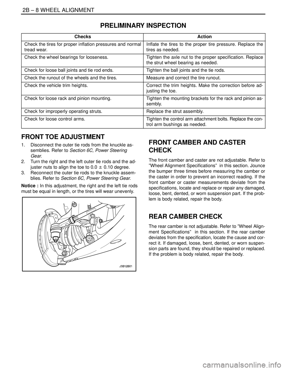
FRONT TOE ADJUSTMENT
1. Disconnect the outer tie rods from the knuckle as-
semblies. Refer to Section 6C, Power Steering
Gear.
2. Turn the right and the left outer tie rods and the ad-
juster nuts to align the toe to 0.0 ± 0.10 degree.
3. Reconnect the outer tie rods to the knuckle assem-
blies. Refer to Section 6C, Power Steering Gear.
Notice : In this adjustment, the right and the left tie rods
must be equal in length, or the tires will wear unevenly.FRONT CAMBER AND CASTER
CHECK
The front camber and caster are not adjustable. Refer to
”Wheel Alignment Specifications” in this section. Jounce
the bumper three times before measuring the camber or
the caster in order to prevent an incorrect reading. If the
front camber or caster measurements deviate from the
specifications, locate and replace or repair any damaged,
loose, bent, dented, or worn suspension part. If the prob-
lem is body related, repair the body.
REAR CAMBER CHECK
The rear camber is not adjustable. Refer to ”Wheel Align-
ment Specifications” in this section. If the rear camber
deviates from the specification, locate the cause and cor-
rect it. If damaged, loose, bent, dented, or worn suspen-
sion parts are found, they should be repaired or replaced.
If the problem is body related, repair the body.
Page 942 of 2643
FRONT SUSPENSION 2C – 25
DAEWOO V–121 BL4
GENERAL DESCRIPTION
AND SYSTEM OPERATION
FRONT SUSPENSION
The front suspension for this vehicle is a combination of
a strut assembly and a knuckle assembly. The strut as-
sembly combines a strut dampener and spring mounted
to the body of the vehicle. The upper end of the strut is iso-
lated by a rubber mount and contains a bearing to allow the
strut to turn. The knuckle is attached to the strut assembly
and pivots on a ball joint bolted to the control arm. The con-
trol arms pivot from the body using rubber bushings.
The ball joint is fastened to the steering knuckle with a
pinch bolt and nut, and to the lower control arm with rivets.
The stabilizer bar interconnects both strut assemblies ofthe vehicle through the stabilizer link and is attached to the
front suspension crossmember. Jounce and rebound
movements affecting one wheel are partially transmitted
to the opposite wheel of the vehicle to stabilize body roll.
When servicing the control arm–to–body attachment and
the stabilizer shaft–to–body insulators, make sure the at-
taching bolts are loose until the control arms are moved to
the trim height, which is curb height. Trim height is the nor-
mal position to which the control arms move when the ve-
hicle is sitting on the ground. Refer to ”General Specifica-
tions” in this section.
The springs in the front suspension of engine family II are
stronger and the strut dampeners heavier than are the
springs and strut dampeners found in the front suspension
of engine family I.
Page 972 of 2643
2E – 10ITIRES AND WHEELS
DAEWOO V–121 BL4
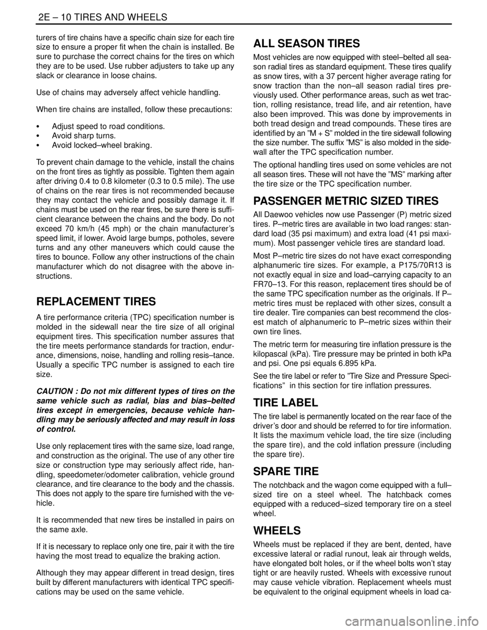
turers of tire chains have a specific chain size for each tire
size to ensure a proper fit when the chain is installed. Be
sure to purchase the correct chains for the tires on which
they are to be used. Use rubber adjusters to take up any
slack or clearance in loose chains.
Use of chains may adversely affect vehicle handling.
When tire chains are installed, follow these precautions:
S Adjust speed to road conditions.
S Avoid sharp turns.
S Avoid locked–wheel braking.
To prevent chain damage to the vehicle, install the chains
on the front tires as tightly as possible. Tighten them again
after driving 0.4 to 0.8 kilometer (0.3 to 0.5 mile). The use
of chains on the rear tires is not recommended because
they may contact the vehicle and possibly damage it. If
chains must be used on the rear tires, be sure there is suffi-
cient clearance between the chains and the body. Do not
exceed 70 km/h (45 mph) or the chain manufacturer’s
speed limit, if lower. Avoid large bumps, potholes, severe
turns and any other maneuvers which could cause the
tires to bounce. Follow any other instructions of the chain
manufacturer which do not disagree with the above in-
structions.
REPLACEMENT TIRES
A tire performance criteria (TPC) specification number is
molded in the sidewall near the tire size of all original
equipment tires. This specification number assures that
the tire meets performance standards for traction, endur-
ance, dimensions, noise, handling and rolling resis–tance.
Usually a specific TPC number is assigned to each tire
size.
CAUTION : Do not mix different types of tires on the
same vehicle such as radial, bias and bias–belted
tires except in emergencies, because vehicle han-
dling may be seriously affected and may result in loss
of control.
Use only replacement tires with the same size, load range,
and construction as the original. The use of any other tire
size or construction type may seriously affect ride, han-
dling, speedometer/odometer calibration, vehicle ground
clearance, and tire clearance to the body and the chassis.
This does not apply to the spare tire furnished with the ve-
hicle.
It is recommended that new tires be installed in pairs on
the same axle.
If it is necessary to replace only one tire, pair it with the tire
having the most tread to equalize the braking action.
Although they may appear different in tread design, tires
built by different manufacturers with identical TPC specifi-
cations may be used on the same vehicle.
ALL SEASON TIRES
Most vehicles are now equipped with steel–belted all sea-
son radial tires as standard equipment. These tires qualify
as snow tires, with a 37 percent higher average rating for
snow traction than the non–all season radial tires pre-
viously used. Other performance areas, such as wet trac-
tion, rolling resistance, tread life, and air retention, have
also been improved. This was done by improvements in
both tread design and tread compounds. These tires are
identified by an ”M + S” molded in the tire sidewall following
the size number. The suffix ”MS” is also molded in the side-
wall after the TPC specification number.
The optional handling tires used on some vehicles are not
all season tires. These will not have the ”MS” marking after
the tire size or the TPC specification number.
PASSENGER METRIC SIZED TIRES
All Daewoo vehicles now use Passenger (P) metric sized
tires. P–metric tires are available in two load ranges: stan-
dard load (35 psi maximum) and extra load (41 psi maxi-
mum). Most passenger vehicle tires are standard load.
Most P–metric tire sizes do not have exact corresponding
alphanumeric tire sizes. For example, a P175/70R13 is
not exactly equal in size and load–carrying capacity to an
FR70–13. For this reason, replacement tires should be of
the same TPC specification number as the originals. If P–
metric tires must be replaced with other sizes, consult a
tire dealer. Tire companies can best recommend the clos-
est match of alphanumeric to P–metric sizes within their
own tire lines.
The metric term for measuring tire inflation pressure is the
kilopascal (kPa). Tire pressure may be printed in both kPa
and psi. One psi equals 6.895 kPa.
See the tire label or refer to ”Tire Size and Pressure Speci-
fications” in this section for tire inflation pressures.
TIRE LABEL
The tire label is permanently located on the rear face of the
driver’s door and should be referred to for tire information.
It lists the maximum vehicle load, the tire size (including
the spare tire), and the cold inflation pressure (including
the spare tire).
SPARE TIRE
The notchback and the wagon come equipped with a full–
sized tire on a steel wheel. The hatchback comes
equipped with a reduced–sized temporary tire on a steel
wheel.
WHEELS
Wheels must be replaced if they are bent, dented, have
excessive lateral or radial runout, leak air through welds,
have elongated bolt holes, or if the wheel bolts won’t stay
tight or are heavily rusted. Wheels with excessive runout
may cause vehicle vibration. Replacement wheels must
be equivalent to the original equipment wheels in load ca-
Page 2207 of 2643
SECTION : 9A
BODY WIRING SYSTEM
CAUTION : Disconnect the negative battery cable before removing or installing any electrical unit or when a tool
or equipment could easily come in contact with exposed electrical terminals. Disconnecting this cable will help
prevent personal injury and damage to the vehicle. The ignition must also be in LOCK unless otherwise noted.
TABLE OF CONTENTS
SCHEMATIC AND ROUTING DIAGRAMS9A–1 . . . . .
Wire Color Chart 9A–1. . . . . . . . . . . . . . . . . . . . . . . . . . .
Power Distribution Schematic 9A–3. . . . . . . . . . . . . . .
Fuse Block Locator (Engine) 9A–12. . . . . . . . . . . . . . .
Fuse Block Locator (Passenger Compartment) 9A–12
Fuse Chart 9A–13. . . . . . . . . . . . . . . . . . . . . . . . . . . . . . Front Harness Routing 9A–15. . . . . . . . . . . . . . . . . . . .
Rear Harness Routing 9A–16. . . . . . . . . . . . . . . . . . . . .
Hatchback Rear Harness Routing 9A–17. . . . . . . . . . .
Floor Harness Routing 9A–18. . . . . . . . . . . . . . . . . . . .
Instrument Harness Routing 9A–19. . . . . . . . . . . . . . . .
Door Harness Routing 9A–20. . . . . . . . . . . . . . . . . . . . .
SCHEMATIC AND ROUTING DIAGRAMS
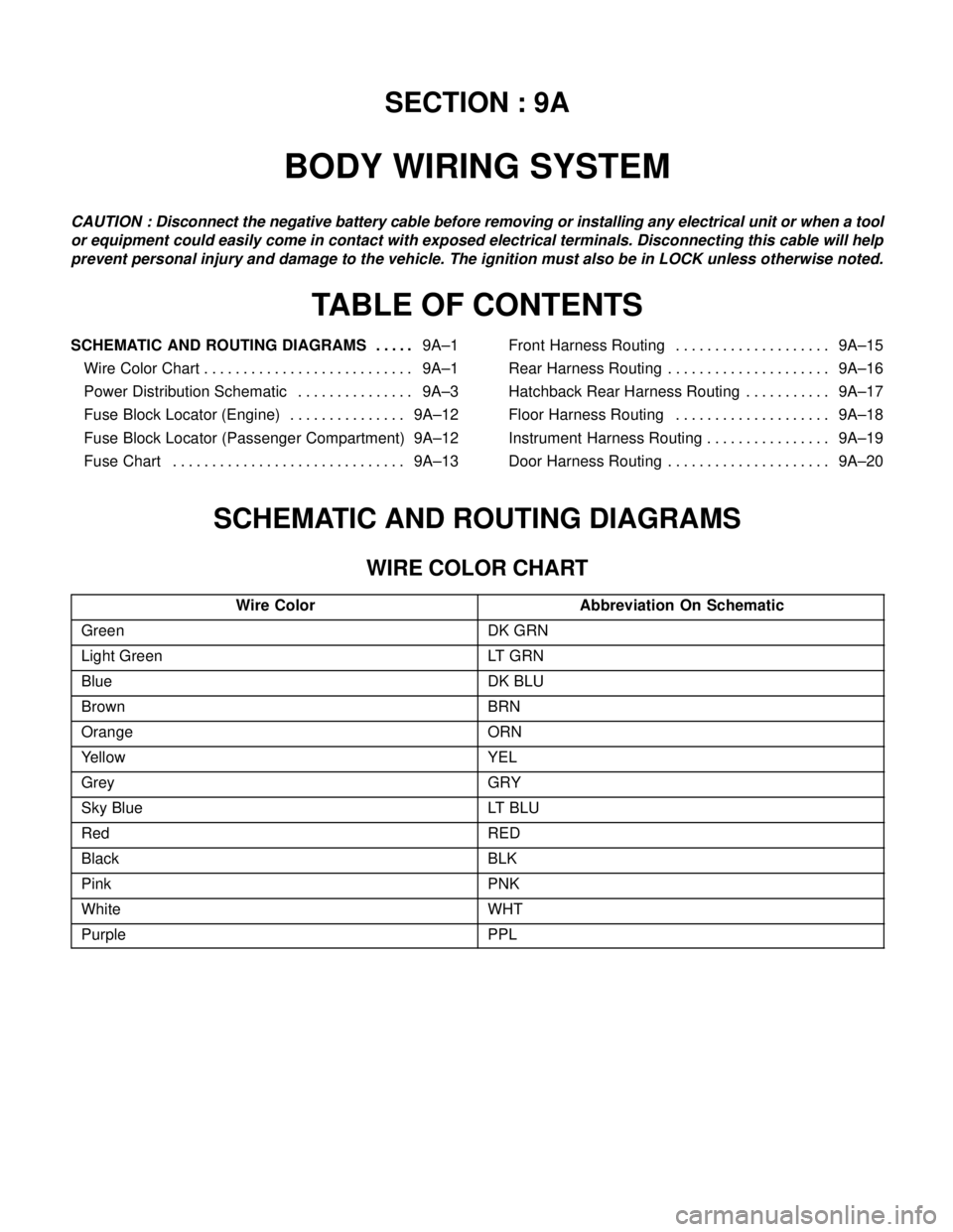
WIRE COLOR CHART
Wire ColorAbbreviation On Schematic
GreenDK GRN
Light GreenLT GRN
BlueDK BLU
BrownBRN
OrangeORN
YellowYEL
GreyGRY
Sky BlueLT BLU
RedRED
BlackBLK
PinkPNK
WhiteWHT
PurplePPL