Page 2291 of 2643
9D – 14IWIPERS/WASHER SYSTEMS
DAEWOO V–121 BL4
MAINTENANCE AND REPAIR
ON–VEHICLE SERVICE
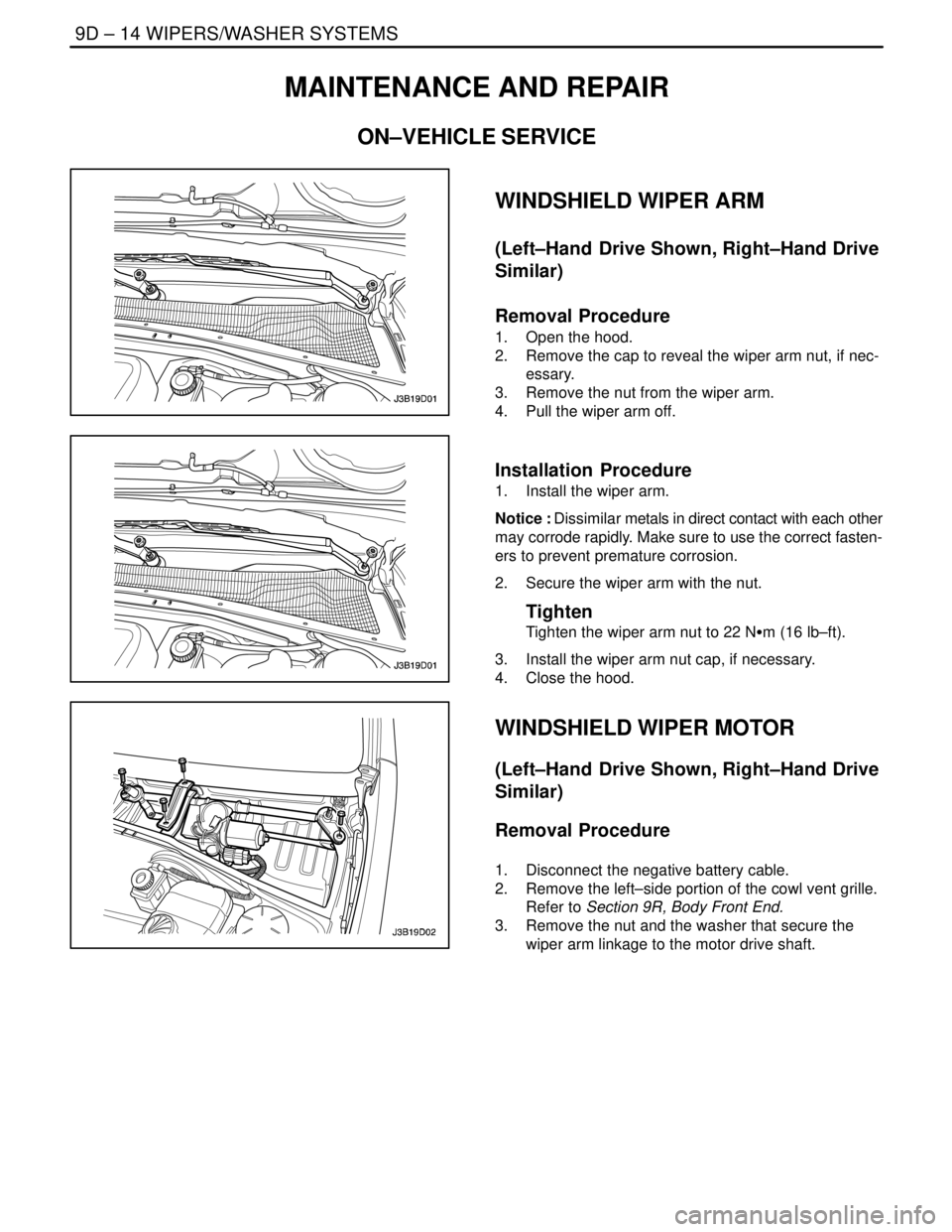
WINDSHIELD WIPER ARM
(Left–Hand Drive Shown, Right–Hand Drive
Similar)
Removal Procedure
1. Open the hood.
2. Remove the cap to reveal the wiper arm nut, if nec-
essary.
3. Remove the nut from the wiper arm.
4. Pull the wiper arm off.
Installation Procedure
1. Install the wiper arm.
Notice : Dissimilar metals in direct contact with each other
may corrode rapidly. Make sure to use the correct fasten-
ers to prevent premature corrosion.
2. Secure the wiper arm with the nut.
Tighten
Tighten the wiper arm nut to 22 NSm (16 lb–ft).
3. Install the wiper arm nut cap, if necessary.
4. Close the hood.
WINDSHIELD WIPER MOTOR
(Left–Hand Drive Shown, Right–Hand Drive
Similar)
Removal Procedure
1. Disconnect the negative battery cable.
2. Remove the left–side portion of the cowl vent grille.
Refer to Section 9R, Body Front End.
3. Remove the nut and the washer that secure the
wiper arm linkage to the motor drive shaft.
Page 2292 of 2643
WIPERS/WASHER SYSTEMS 9D – 15
DAEWOO V–121 BL4
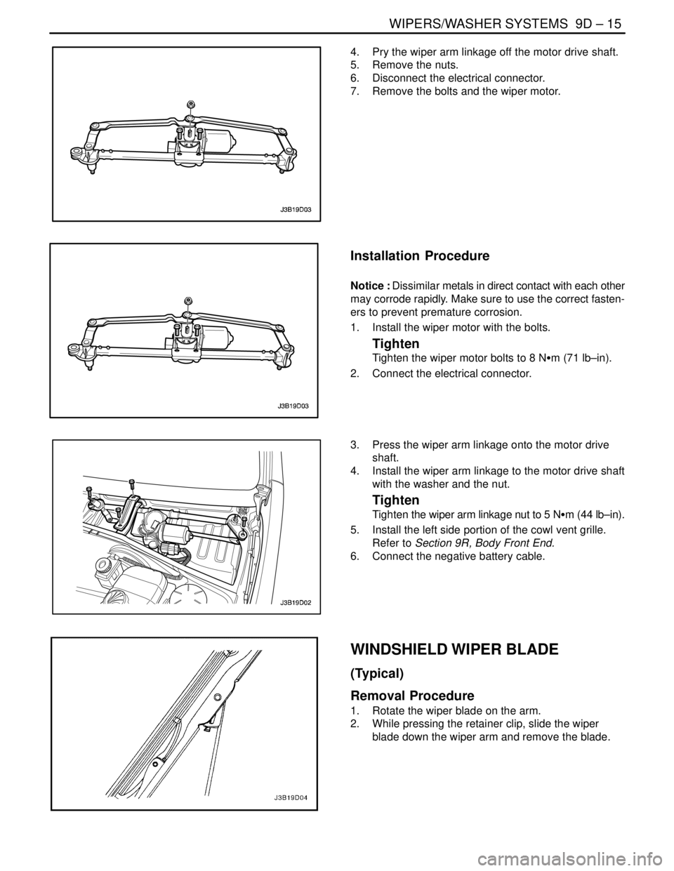
4. Pry the wiper arm linkage off the motor drive shaft.
5. Remove the nuts.
6. Disconnect the electrical connector.
7. Remove the bolts and the wiper motor.
Installation Procedure
Notice : Dissimilar metals in direct contact with each other
may corrode rapidly. Make sure to use the correct fasten-
ers to prevent premature corrosion.
1. Install the wiper motor with the bolts.
Tighten
Tighten the wiper motor bolts to 8 NSm (71 lb–in).
2. Connect the electrical connector.
3. Press the wiper arm linkage onto the motor drive
shaft.
4. Install the wiper arm linkage to the motor drive shaft
with the washer and the nut.
Tighten
Tighten the wiper arm linkage nut to 5 NSm (44 lb–in).
5. Install the left side portion of the cowl vent grille.
Refer to Section 9R, Body Front End.
6. Connect the negative battery cable.
WINDSHIELD WIPER BLADE
(Typical)
Removal Procedure
1. Rotate the wiper blade on the arm.
2. While pressing the retainer clip, slide the wiper
blade down the wiper arm and remove the blade.
Page 2377 of 2643
SECTION : 9K
SQUEAKS AND RATTLES
TABLE OF CONTENTS
DIAGNOSIS9K–1 . . . . . . . . . . . . . . . . . . . . . . . . . . . . . . . .
Squeak and Rattle Diagnosis 9K–1. . . . . . . . . . . . . . . .
MAINTENANCE AND REPAIR9K–3 . . . . . . . . . . . . . . . ON–VEHICLE SERVICE 9K–3. . . . . . . . . . . . . . . . . . . . .
Squeak and Rattle Repair 9K–3. . . . . . . . . . . . . . . . . . .
DIAGNOSIS
SQUEAK AND RATTLE DIAGNOSIS
Rattle Coming From the Side Rail
ChecksAction
Check the brake lines.S Tap lightly on the brake lines and listen for a rattle.
S Install plastic tie straps to secure the brake lines
tightly together.
Rattle Under Vehicle at Higher RPM
ChecksAction
Check for heat shield contact with the underbody.S Raise the vehicle and perform a visual inspection.
S Bend the heat shield slightly to gain clearance from
the underbody.
Squeak From the Front of the Vehicle in Cold Weather
ChecksAction
Check the front stabilizer shaft insulators.S While the vehicle is cold, perform a test drive and
achieve full front suspension travel by driving through
a dip in the road.
S Remove the insulators and wrap teflon tape around
the stabilizer shaft. Reinstall the insulators over the
tape.
Thump From Rear of Vehicle on Bumps
ChecksAction
Check for a properly secured spare tire in the rear
compartment.S Open the rear compartment and perform a visual
inspection of the spare tire and the tools.
S Tightly secure the spare tire and all tools.
S Perform a road test to verify that the noise is elimi-
nated.
Page 2389 of 2643
9L – 10IGLASS AND MIRRORS
DAEWOO V–121 BL4
MAINTENANCE AND REPAIR
ON–VEHICLE SERVICE
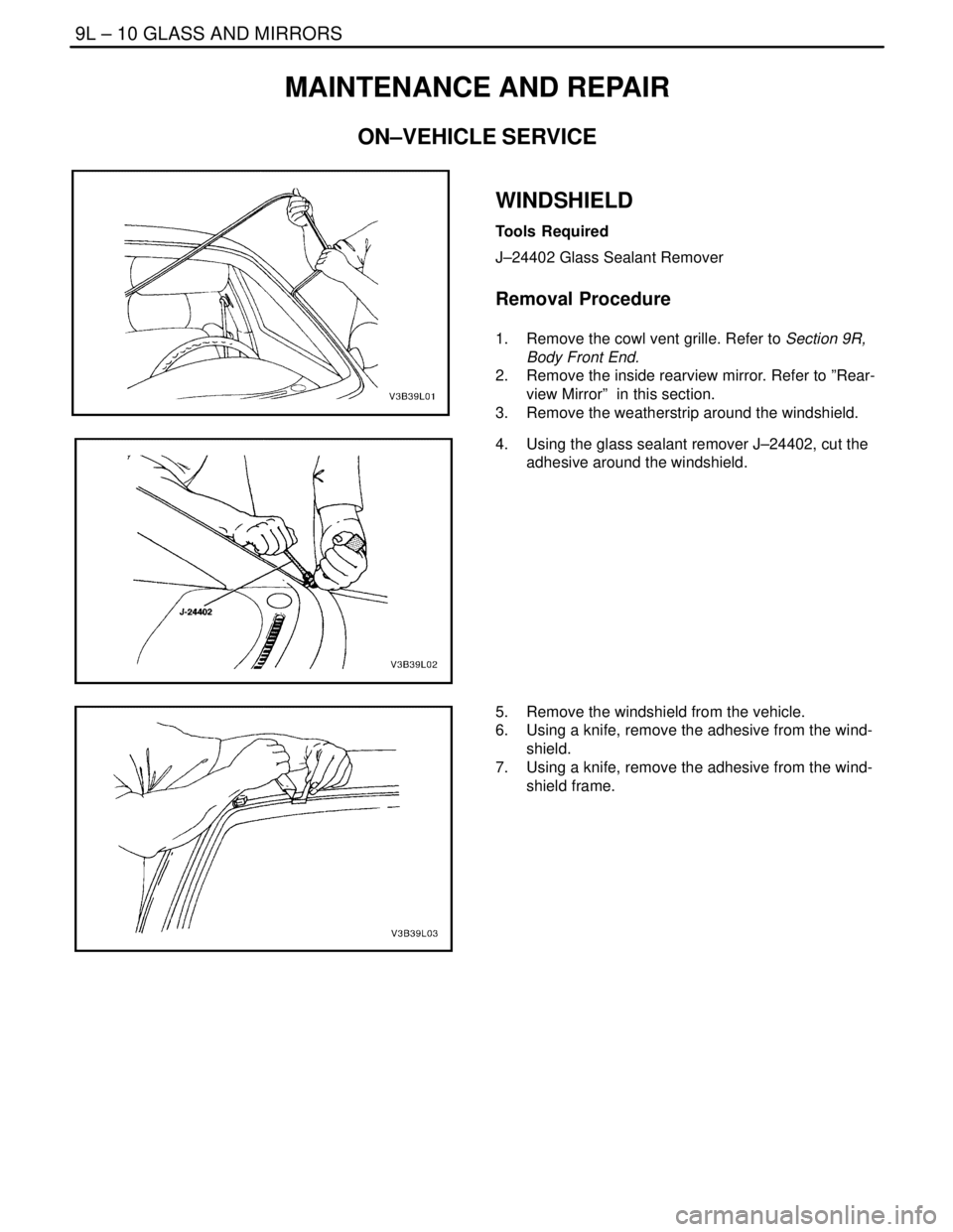
WINDSHIELD
Tools Required
J–24402 Glass Sealant Remover
Removal Procedure
1. Remove the cowl vent grille. Refer to Section 9R,
Body Front End.
2. Remove the inside rearview mirror. Refer to ”Rear-
view Mirror” in this section.
3. Remove the weatherstrip around the windshield.
4. Using the glass sealant remover J–24402, cut the
adhesive around the windshield.
5. Remove the windshield from the vehicle.
6. Using a knife, remove the adhesive from the wind-
shield.
7. Using a knife, remove the adhesive from the wind-
shield frame.
Page 2390 of 2643
GLASS AND MIRRORS 9L – 11
DAEWOO V–121 BL4
Installation Procedure
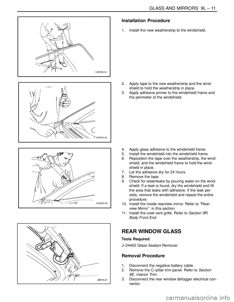
1. Install the new weatherstrip to the windshield.
2. Apply tape to the new weatherstrip and the wind-
shield to hold the weatherstrip in place.
3. Apply adhesive primer to the windshield frame and
the perimeter of the windshield.
4. Apply glass adhesive to the windshield frame.
5. Install the windshield into the windshield frame.
6. Reposition the tape over the weatherstrip, the wind-
shield, and the windshield frame to hold the wind-
shield in place.
7. Let the adhesive dry for 24 hours.
8. Remove the tape.
9. Check for waterleaks by pouring water on the wind-
shield. If a leak is found, dry the windshield and fill
the area that leaks with adhesive. If the leak per-
sists, remove the windshield and repeat the entire
procedure.
10. Install the inside rearview mirror. Refer to ”Rear-
view Mirror” in this section.
11. Install the cowl vent grille. Refer to Section 9R,
Body Front End.
REAR WINDOW GLASS
Tools Required
J–24402 Glass Sealant Remover
Removal Procedure
1. Disconnect the negative battery cable.
2. Remove the C–pillar trim panel. Refer to Section
9E, Interior Trim.
3. Disconnect the rear window defogger electrical con-
nector.
Page 2411 of 2643
9N – 8IFRAME AND UNDERBODY
DAEWOO V–121 BL4
GENERAL DESCRIPTION
AND SYSTEM OPERATION
GENERAL BODY CONSTRUCTION
This vehicle is constructed with a unitized body which in-
corporates integral front and rear frame side rails.
The front suspension lower control arms are bolted to and
retained by supports, one each on the right and left sides.
The front suspension lower control arm supports are at-
tached to the underbody with three bolts at two locations.
The engine is bolted to the integral front side rails. The
suspension strut towers must be dimensionally correct in
relation to the remainder of the underbody in order to main-
tain specified suspension strut and caster/ camber angles.Since the individual underbody parts contribute directly to
the overall strength of the body, it is essential to observe
proper welding techniques during service repair opera-
tions. The underbody parts should be properly sealed and
rustproofed whenever body repair operations destroy or
damage the original sealing and rustproofing. When rust-
proofing critical underbody parts, use a good–quality type
of air–dry primer, such as a corrosion–resistant chromate
or an equivalent material. Combination–type primer/sur-
facers are not recommended.
ENGINE UNDER COVERS
The engine under covers are molded pieces of plastic that
serve as shields for the underside of the engine. The cov-
ers help protect the engine from small rocks, gravel and
other objects that would otherwise come into contact with
the engine during normal driving conditions.
Page 2413 of 2643
9O – 2IBUMPERS AND FASCIAS
DAEWOO V–121 BL4
MAINTENANCE AND REPAIR
ON–VEHICLE SERVICE
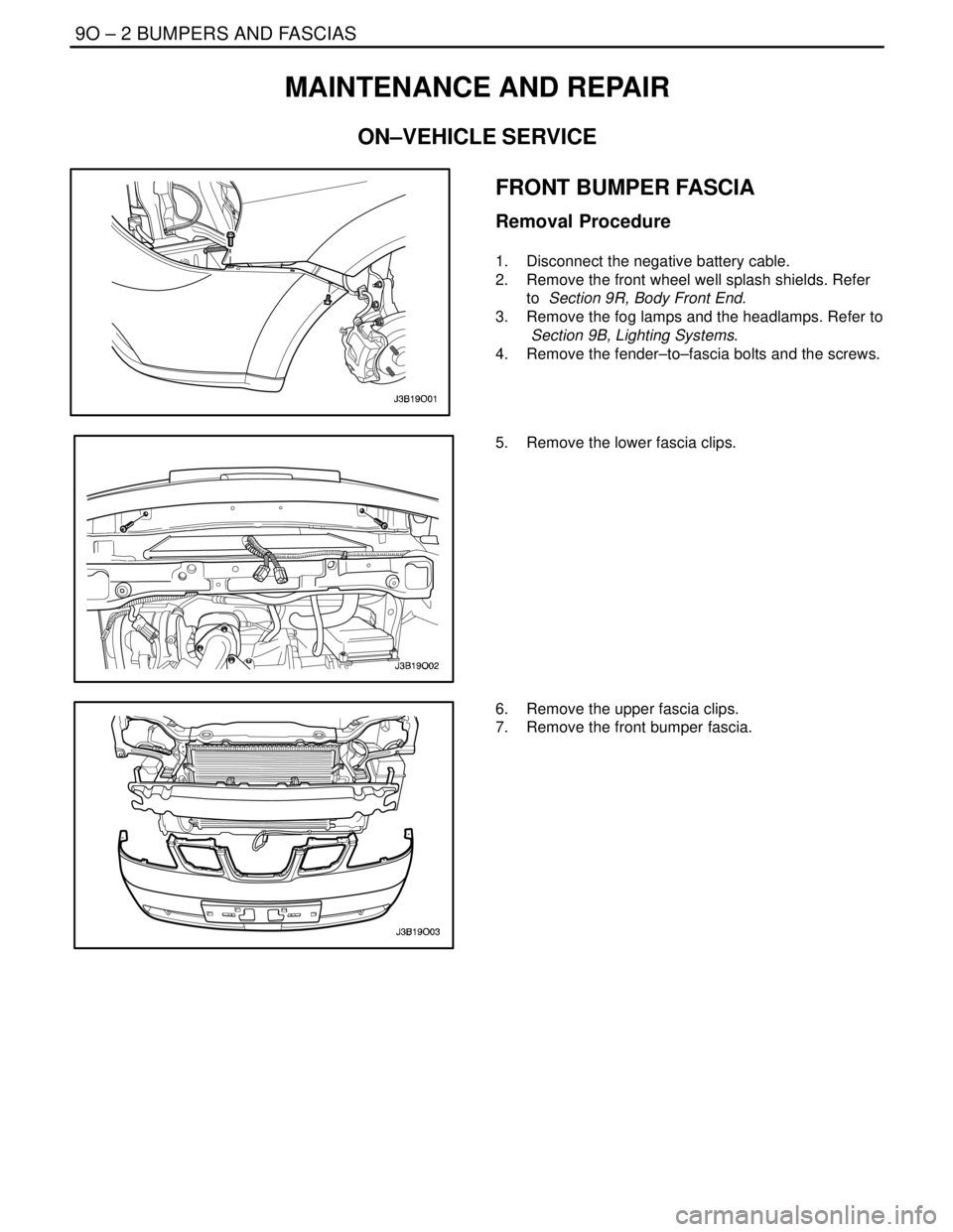
FRONT BUMPER FASCIA
Removal Procedure
1. Disconnect the negative battery cable.
2. Remove the front wheel well splash shields. Refer
to Section 9R, Body Front End.
3. Remove the fog lamps and the headlamps. Refer to
Section 9B, Lighting Systems.
4. Remove the fender–to–fascia bolts and the screws.
5. Remove the lower fascia clips.
6. Remove the upper fascia clips.
7. Remove the front bumper fascia.
Page 2442 of 2643
9P – 22IDOORS
DAEWOO V–121 BL4
DOOR LOCK STRIKER ADJUSTMENT
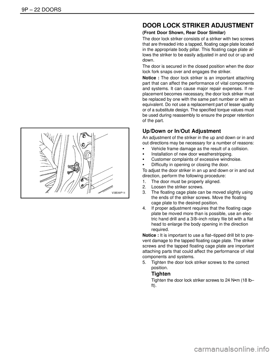
(Front Door Shown, Rear Door Similar)
The door lock striker consists of a striker with two screws
that are threaded into a tapped, floating cage plate located
in the appropriate body pillar. This floating cage plate al-
lows the striker to be easily adjusted in and out or up and
down.
The door is secured in the closed position when the door
lock fork snaps over and engages the striker.
Notice : The door lock striker is an important attaching
part that can affect the performance of vital components
and systems. It can cause major repair expenses. If re-
placement becomes necessary, the door lock striker must
be replaced by one with the same part number or with an
equivalent. Do not use a replacement part of lesser quality
or of a substitute design. The specified torque values must
be used during reassembly to ensure the proper retention
of the part.
Up/Down or In/Out Adjustment
An adjustment of the striker in the up and down or in and
out directions may be necessary for a number of reasons:
S Vehicle frame damage as the result of a collision.
S Installation of new door weatherstripping.
S Customer complaints of excessive windnoise.
S Difficulty in opening or closing the door.
To adjust the door striker in an up and down or in and out
direction, perform the following procedure:
1. The door must be properly aligned.
2. Loosen the striker screws.
3. The floating cage plate can be moved slightly using
the ends of the striker screws. Move the floating
cage plate to the desired position.
4. If proper adjustment requires that the floating cage
plate be moved more than is possible, use an elec-
tric hand drill and a 3/8–inch rotary file bit with a flat
head to enlarge the body opening in the direction
required.
Notice : It is important to use a flat–tipped drill bit to pre-
vent damage to the tapped floating cage plate. The striker
screws and the tapped floating cage plate are important
attaching parts that could affect the performance of vital
components and systems.
5. Tighten the door lock striker screws to the correct
position.
Tighten
Tighten the door lock striker screws to 24 NSm (18 lb–
ft).