2004 CHRYSLER VOYAGER torque
[x] Cancel search: torquePage 1888 of 2585
OPERATION
Transmission output is directed to an integral dif-
ferential by a transfer gear system in the following
input-to-output ratios:
First ............................... 2.84 : 1
Second ............................. 1.57 : 1
Third .............................. 1.00 : 1
Overdrive ........................... 0.69 : 1
Reverse ............................ 2.21 : 1
DIAGNOSIS AND TESTING
DIAGNOSIS AND TESTING - 4XTE TRANSAXLE
GENERAL DIAGNOSIS
NOTE: Before attempting any repair on a 4XTE four-
speed automatic transaxle, check for diagnostic trou-
ble codes (DTC's) using the DRB scan tool. Refer to
the Transmission Diagnostic Procedures Manual.
Transaxle malfunctions may be caused by these
general conditions: ² Poor engine performance
² Improper adjustments
² Hydraulic malfunctions
² Mechanical malfunctions
² Electronic malfunctions
Diagnosis of these problems should always begin by
checking the easily accessible variables: fluid level and
condition, gearshift cable adjustment. Then perform a
road test to determine if the problem has been corrected
or that more diagnosis is necessary. If the problem per-
sists after the preliminary tests and corrections are com-
pleted, hydraulic pressure checks should be performed.
DIAGNOSIS AND TESTING - ROAD TEST
Prior to performing a road test, verify that the
fluid level, fluid condition, and linkage adjustment
have been approved. During the road test, the transaxle should be oper-
ated in each position to check for slipping and any
variation in shifting. If the vehicle operates properly at highway speeds,
but has poor acceleration, the converter stator over-
running clutch may be slipping. If acceleration is nor-
mal, but high throttle opening is needed to maintain
highway speeds, the converter stator clutch may
have seized. Both of these stator defects require
replacement of the torque converter and thorough
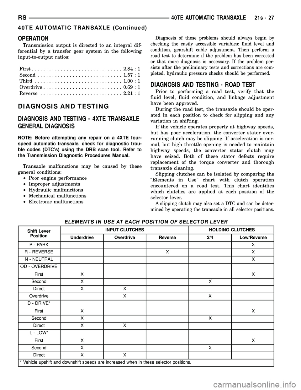
transaxle cleaning. Slipping clutches can be isolated by comparing the
ªElements in Useº chart with clutch operation
encountered on a road test. This chart identifies
which clutches are applied at each position of the
selector lever.
A slipping clutch may also set a DTC and can be deter-
mined by operating the transaxle in all selector positions.
ELEMENTS IN USE AT EACH POSITION OF SELECTOR LEVER
Shift Lever Position INPUT CLUTCHES HOLDING CLUTCHES
Underdrive Overdrive Reverse 2/4 Low/Reverse
P - PARK X
R - REVERSE X X N - NEUTRAL X
OD - OVERDRIVE
First X X
Second X X Direct X X
Overdrive X X
D - DRIVE*
First X X
Second X X Direct X X
L - LOW*
First X X
Second X X
Direct X X
* Vehicle upshift and downshift speeds are increased when in these selector positions.
RS 40TE AUTOMATIC TRANSAXLE21s-27
40TE AUTOMATIC TRANSAXLE (Continued)
Page 1889 of 2585
The process of elimination can be used to detect
any unit which slips and to confirm proper operation
of good units. Road test analysis can diagnose slip-
ping units, but the cause of the malfunction cannot
be determined. Practically any condition can be
caused by leaking hydraulic circuits or sticking
valves.
DIAGNOSIS AND TESTING - HYDRAULIC
PRESSURE TESTS
Pressure testing is a very important step in the
diagnostic procedure. These tests usually reveal the
cause of most hydraulic transaxle problems. Before performing pressure tests, be certain that
fluid level and condition, and shift cable adjustments
have been checked and approved. Fluid must be at
operating temperature (150 to 200 degrees F.). Install an engine tachometer, raise vehicle on hoist
which allows front wheels to turn, and position
tachometer so it can be read. Attach 300 psi gauge (C-3293SP) to port(s)
required for test(s) being conducted. Use adapter set
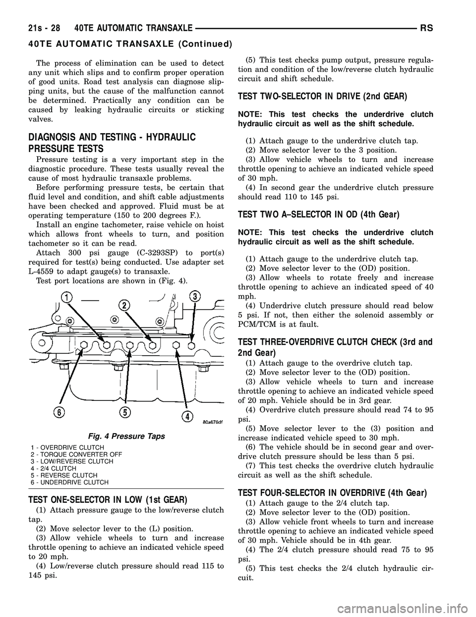
L-4559 to adapt gauge(s) to transaxle. Test port locations are shown in (Fig. 4).
TEST ONE-SELECTOR IN LOW (1st GEAR)
(1) Attach pressure gauge to the low/reverse clutch
tap. (2) Move selector lever to the (L) position.
(3) Allow vehicle wheels to turn and increase
throttle opening to achieve an indicated vehicle speed
to 20 mph. (4) Low/reverse clutch pressure should read 115 to
145 psi. (5) This test checks pump output, pressure regula-
tion and condition of the low/reverse clutch hydraulic
circuit and shift schedule.
TEST TWO-SELECTOR IN DRIVE (2nd GEAR)
NOTE: This test checks the underdrive clutch
hydraulic circuit as well as the shift schedule.
(1) Attach gauge to the underdrive clutch tap.
(2) Move selector lever to the 3 position.
(3) Allow vehicle wheels to turn and increase
throttle opening to achieve an indicated vehicle speed
of 30 mph. (4) In second gear the underdrive clutch pressure
should read 110 to 145 psi.
TEST TWO A±SELECTOR IN OD (4th Gear)
NOTE: This test checks the underdrive clutch
hydraulic circuit as well as the shift schedule.
(1) Attach gauge to the underdrive clutch tap.
(2) Move selector lever to the (OD) position.
(3) Allow wheels to rotate freely and increase
throttle opening to achieve an indicated speed of 40
mph. (4) Underdrive clutch pressure should read below
5 psi. If not, then either the solenoid assembly or
PCM/TCM is at fault.
TEST THREE-OVERDRIVE CLUTCH CHECK (3rd and
2nd Gear)
(1) Attach gauge to the overdrive clutch tap.
(2) Move selector lever to the (OD) position.
(3) Allow vehicle wheels to turn and increase
throttle opening to achieve an indicated vehicle speed
of 20 mph. Vehicle should be in 3rd gear. (4) Overdrive clutch pressure should read 74 to 95
psi. (5) Move selector lever to the (3) position and
increase indicated vehicle speed to 30 mph. (6) The vehicle should be in second gear and over-
drive clutch pressure should be less than 5 psi. (7) This test checks the overdrive clutch hydraulic
circuit as well as the shift schedule.
TEST FOUR-SELECTOR IN OVERDRIVE (4th Gear)
(1) Attach gauge to the 2/4 clutch tap.
(2) Move selector lever to the (OD) position.
(3) Allow vehicle front wheels to turn and increase
throttle opening to achieve an indicated vehicle speed
of 30 mph. Vehicle should be in 4th gear. (4) The 2/4 clutch pressure should read 75 to 95
psi. (5) This test checks the 2/4 clutch hydraulic cir-
cuit.
Fig. 4 Pressure Taps
1 - OVERDRIVE CLUTCH
2 - TORQUE CONVERTER OFF
3 - LOW/REVERSE CLUTCH
4 - 2/4 CLUTCH
5 - REVERSE CLUTCH
6 - UNDERDRIVE CLUTCH
21s - 28 40TE AUTOMATIC TRANSAXLERS
40TE AUTOMATIC TRANSAXLE (Continued)
Page 1890 of 2585
TEST FIVE-SELECTOR IN OVERDRIVE (4th Gear-CC
on)
(1) Attach gauge to the torque converter clutch off
pressure tap. (2) Move selector lever to the (OD) position.
(3) Allow vehicle wheels to turn and increase
throttle opening to achieve an indicated vehicle speed
of 50 mph. Vehicle should be in 4th gear, CC on.
CAUTION: Both wheels must turn at the same
speed.
(4) Torque converter clutch off pressure should be
less than 5 psi. (5) This test checks the torque converter clutch
hydraulic circuit.
TEST SIX-SELECTOR IN REVERSE
(1) Attach gauges to the reverse and LR clutch
tap. (2) Move selector lever to the (R) position.
(3) Read reverse clutch pressure with output sta-
tionary (foot on brake) and throttle opened to achieve
1500 rpm. (4) Reverse and LR clutch pressure should read
165 to 235 psi. (5) This test checks the reverse clutch hydraulic
circuit.
TEST RESULT INDICATIONS
(1) If proper line pressure is found in any one test,
the pump and pressure regulator are working prop-
erly. (2) Low pressure in all positions indicates a defec-
tive pump, a clogged filter, or a stuck pressure regu-
lator valve. (3) Clutch circuit leaks are indicated if pressures
do not fall within the specified pressure range. (4) If the overdrive clutch pressure is greater than
5 psi in Step 4 of Test Three, a worn reaction shaft
seal ring or a defective solenoid assembly is indi-
cated. (5) If the underdrive clutch pressure is greater
than 5 psi in Step 4 of Test Two A, a defective sole-
noid assembly or PCM/TCM is the cause.
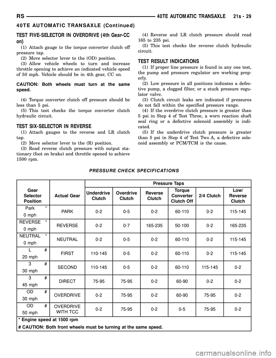
PRESSURE CHECK SPECIFICATIONS
Pressure Taps
Gear
Selector
Position Actual Gear
Underdrive
Clutch Overdrive
Clutch Reverse
Clutch Torque
Converter
Clutch Off 2/4 Clutch Low/
Reverse Clutch
Park * PARK 0-2 0-5 0-2 60-110 0-2 115-145
0 mph
REVERSE * REVERSE 0-2 0-7 165-235 50-100 0-2 165-235
0 mph
NEUTRAL * NEUTRAL 0-2 0-5 0-2 60-110 0-2 115-145
0 mph
L# FIRST 110-145 0-5 0-2 60-110 0-2 115-145
20 mph
3# SECOND 110-145 0-5 0-2 60-110 115-145 0-2
30 mph
3# DIRECT 75-95 75-95 0-2 60-90 0-2 0-2
45 mph
OD # OVERDRIVE 0-2 75-95 0-2 60-90 75-95 0-2
30 mph
OD # OVERDRIVE
WITH TCC 0-2 75-95 0-2 0-5 75-95 0-2
50 mph
* Engine speed at 1500 rpm
# CAUTION: Both front wheels must be turning at the same speed.
RS 40TE AUTOMATIC TRANSAXLE21s-29
40TE AUTOMATIC TRANSAXLE (Continued)
Page 1891 of 2585
DIAGNOSIS AND TESTING - CLUTCH AIR
PRESSURE TESTS
Inoperative clutches can be located using a series
of tests by substituting air pressure for fluid pressure
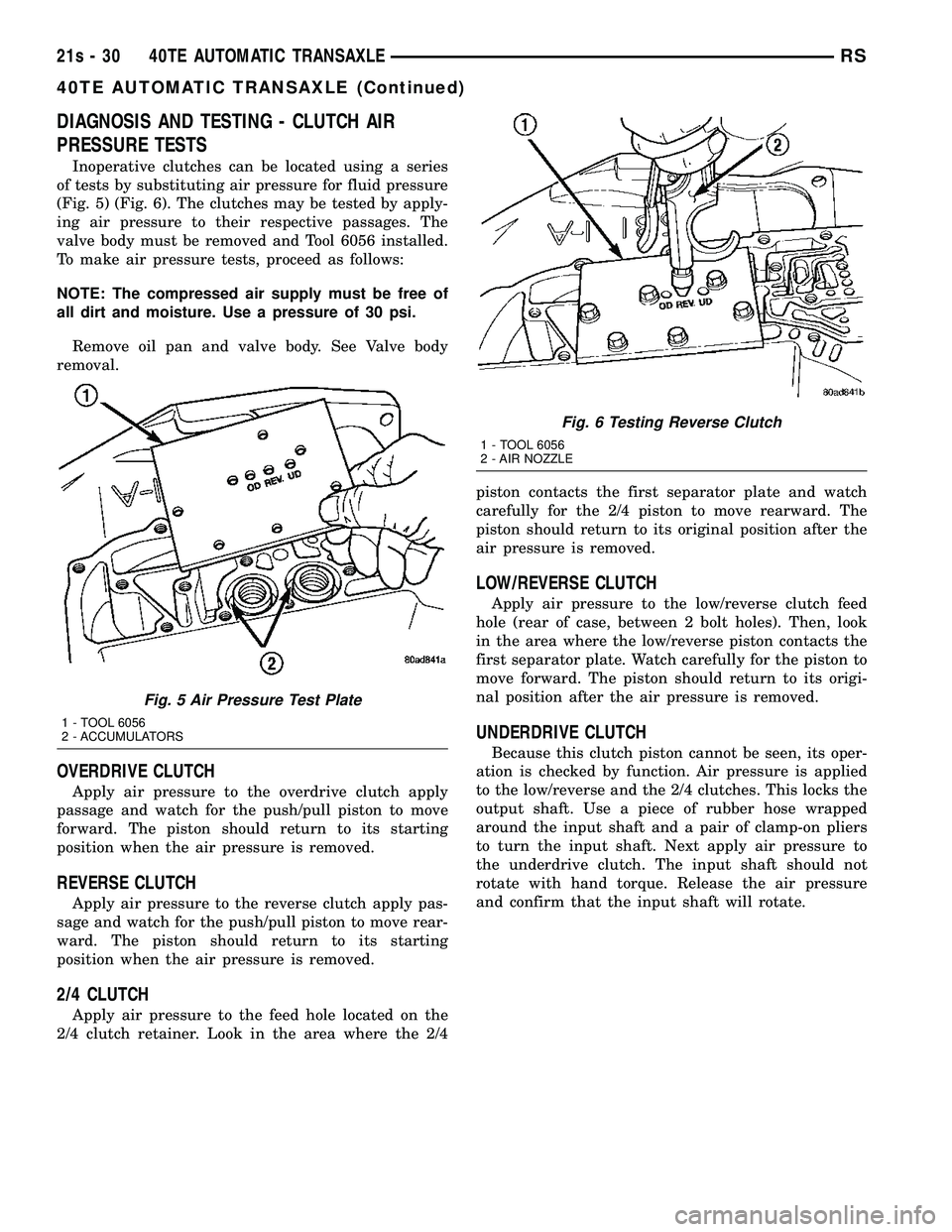
(Fig. 5) (Fig. 6). The clutches may be tested by apply-
ing air pressure to their respective passages. The
valve body must be removed and Tool 6056 installed.
To make air pressure tests, proceed as follows:
NOTE: The compressed air supply must be free of
all dirt and moisture. Use a pressure of 30 psi.
Remove oil pan and valve body. See Valve body
removal.
OVERDRIVE CLUTCH
Apply air pressure to the overdrive clutch apply
passage and watch for the push/pull piston to move
forward. The piston should return to its starting
position when the air pressure is removed.
REVERSE CLUTCH
Apply air pressure to the reverse clutch apply pas-
sage and watch for the push/pull piston to move rear-
ward. The piston should return to its starting
position when the air pressure is removed.
2/4 CLUTCH
Apply air pressure to the feed hole located on the
2/4 clutch retainer. Look in the area where the 2/4 piston contacts the first separator plate and watch
carefully for the 2/4 piston to move rearward. The
piston should return to its original position after the
air pressure is removed.
LOW/REVERSE CLUTCH
Apply air pressure to the low/reverse clutch feed
hole (rear of case, between 2 bolt holes). Then, look
in the area where the low/reverse piston contacts the
first separator plate. Watch carefully for the piston to
move forward. The piston should return to its origi-
nal position after the air pressure is removed.
UNDERDRIVE CLUTCH
Because this clutch piston cannot be seen, its oper-
ation is checked by function. Air pressure is applied
to the low/reverse and the 2/4 clutches. This locks the
output shaft. Use a piece of rubber hose wrapped
around the input shaft and a pair of clamp-on pliers
to turn the input shaft. Next apply air pressure to
the underdrive clutch. The input shaft should not
rotate with hand torque. Release the air pressure
and confirm that the input shaft will rotate.
Fig. 5 Air Pressure Test Plate
1 - TOOL 6056
2 - ACCUMULATORS
Fig. 6 Testing Reverse Clutch
1 - TOOL 6056
2 - AIR NOZZLE
21s - 30 40TE AUTOMATIC TRANSAXLERS
40TE AUTOMATIC TRANSAXLE (Continued)
Page 1892 of 2585
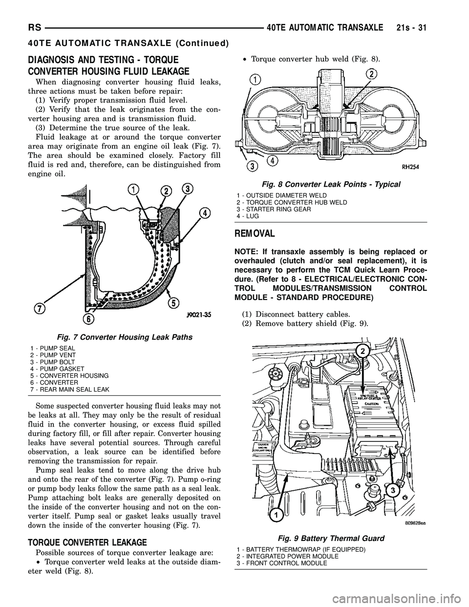
DIAGNOSIS AND TESTING - TORQUE
CONVERTER HOUSING FLUID LEAKAGE
When diagnosing converter housing fluid leaks,
three actions must be taken before repair: (1) Verify proper transmission fluid level.
(2) Verify that the leak originates from the con-
verter housing area and is transmission fluid. (3) Determine the true source of the leak.
Fluid leakage at or around the torque converter
area may originate from an engine oil leak (Fig. 7).
The area should be examined closely. Factory fill
fluid is red and, therefore, can be distinguished from
engine oil.
Some suspected converter housing fluid leaks may not
be leaks at all. They may only be the result of residual
fluid in the converter housing, or excess fluid spilled
during factory fill, or fill after repair. Converter housing
leaks have several potential sources. Through careful
observation, a leak source can be identified before
removing the transmission for repair. Pump seal leaks tend to move along the drive hub
and onto the rear of the converter (Fig. 7). Pump o-ring
or pump body leaks follow the same path as a seal leak.
Pump attaching bolt leaks are generally deposited on
the inside of the converter housing and not on the con-
verter itself. Pump seal or gasket leaks usually travel
down the inside of the converter housing (Fig. 7).
TORQUE CONVERTER LEAKAGE
Possible sources of torque converter leakage are:
² Torque converter weld leaks at the outside diam-
eter weld (Fig. 8). ²
Torque converter hub weld (Fig. 8).
REMOVAL
NOTE: If transaxle assembly is being replaced or
overhauled (clutch and/or seal replacement), it is
necessary to perform the TCM Quick Learn Proce-
dure. (Refer t o 8 - ELECTRICAL/ELECTRONIC CON-
TROL MODULES/TRANSMISSION CONTROL
MODULE - STANDARD PROCEDURE)
(1) Disconnect battery cables.
(2) Remove battery shield (Fig. 9).
Fig. 7 Converter Housing Leak Paths
1 - PUMP SEAL
2 - PUMP VENT
3 - PUMP BOLT
4 - PUMP GASKET
5 - CONVERTER HOUSING
6 - CONVERTER
7 - REAR MAIN SEAL LEAK
Fig. 8 Converter Leak Points - Typical
1 - OUTSIDE DIAMETER WELD
2 - TORQUE CONVERTER HUB WELD
3 - STARTER RING GEAR
4 - LUG
Fig. 9 Battery Thermal Guard
1 - BATTERY THERMOWRAP (IF EQUIPPED)
2 - INTEGRATED POWER MODULE
3 - FRONT CONTROL MODULE
RS 40TE AUTOMATIC TRANSAXLE21s-31
40TE AUTOMATIC TRANSAXLE (Continued)
Page 1894 of 2585
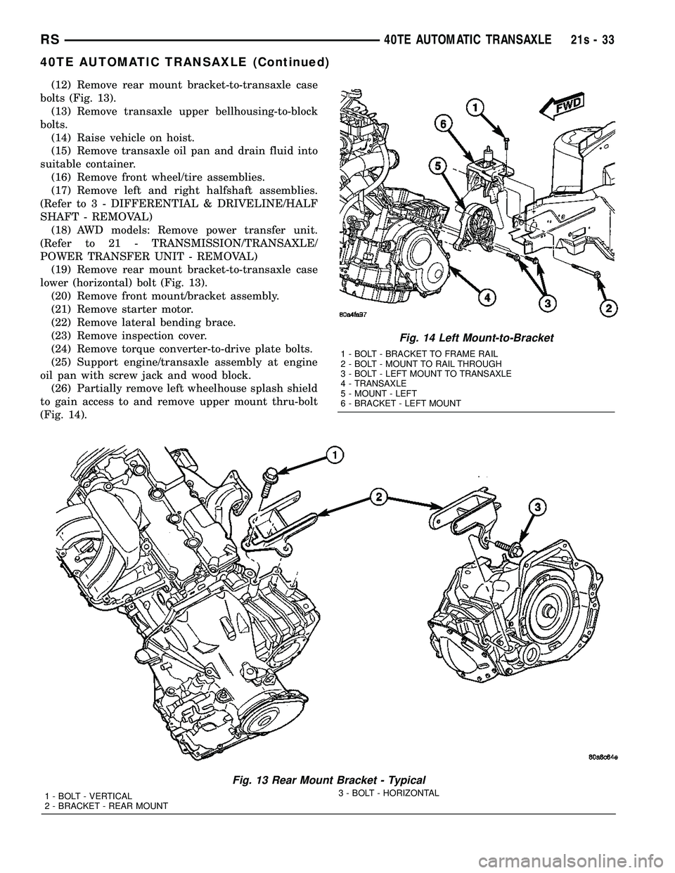
(12) Remove rear mount bracket-to-transaxle case
bolts (Fig. 13). (13) Remove transaxle upper bellhousing-to-block
bolts. (14) Raise vehicle on hoist.
(15) Remove transaxle oil pan and drain fluid into
suitable container. (16) Remove front wheel/tire assemblies.
(17) Remove left and right halfshaft assemblies.
(Refer t o 3 - DIFFERENTIAL & DRIVELINE/HALF
SHAFT - REMOVAL) (18) AWD models: Remove power transfer unit.
(Refer to 21 - TRANSMISSION/TRANSAXLE/
POWER TRANSFER UNIT - REMOVAL) (19) Remove rear mount bracket-to-transaxle case
lower (horizontal) bolt (Fig. 13). (20) Remove front mount/bracket assembly.
(21) Remove starter motor.
(22) Remove lateral bending brace.
(23) Remove inspection cover.
(24) Remove torque converter-to-drive plate bolts.
(25) Support engine/transaxle assembly at engine
oil pan with screw jack and wood block. (26) Partially remove left wheelhouse splash shield
to gain access to and remove upper mount thru-bolt
(Fig. 14).
Fig. 13 Rear Mount Bracket - Typical
1 - BOLT - VERTICAL
2 - BRACKET - REAR MOUNT 3 - BOLT - HORIZONTAL
Fig. 14 Left Mount-to-Bracket
1 - BOLT - BRACKET TO FRAME RAIL
2 - BOLT - MOUNT TO RAIL THROUGH
3 - BOLT - LEFT MOUNT TO TRANSAXLE
4 - TRANSAXLE
5 - MOUNT - LEFT
6 - BRACKET - LEFT MOUNT
RS
40TE AUTOMATIC TRANSAXLE21s-33
40TE AUTOMATIC TRANSAXLE (Continued)
Page 1913 of 2585
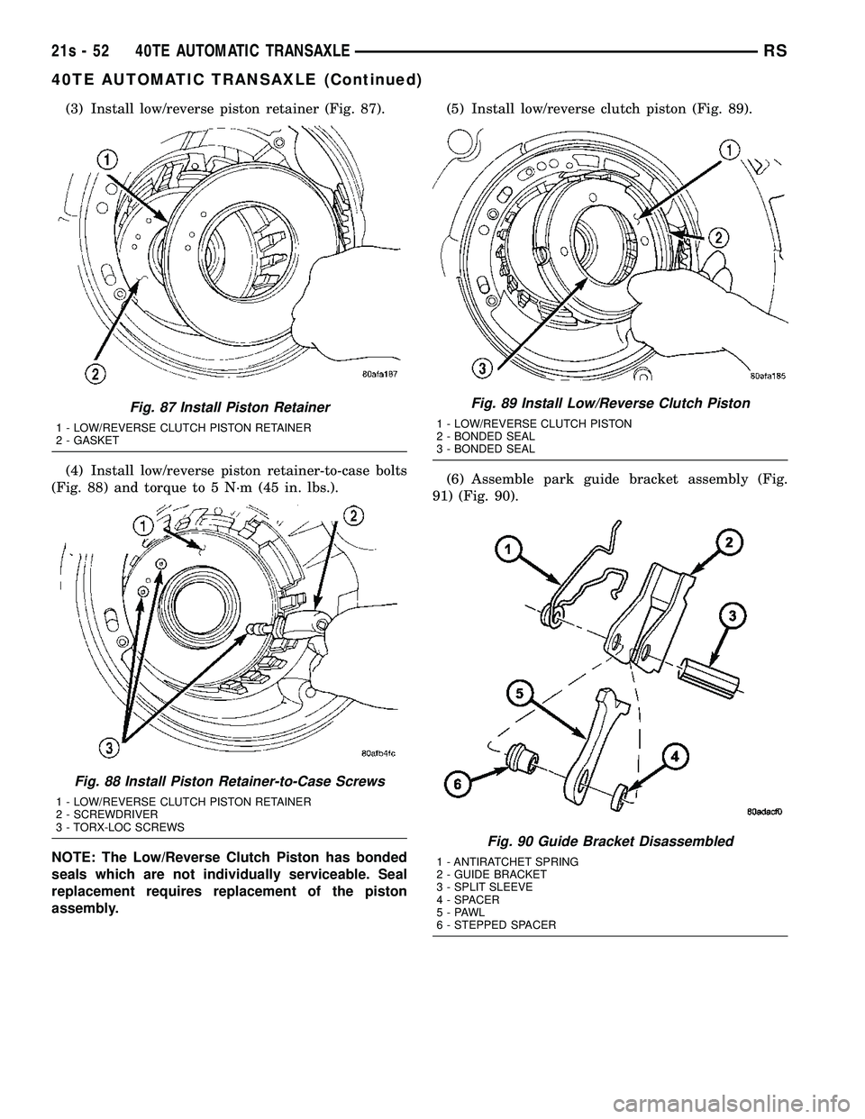
(3) Install low/reverse piston retainer (Fig. 87).
(4) Install low/reverse piston retainer-to-case bolts
(Fig. 88) and torque to 5 N´m (45 in. lbs.).
NOTE: The Low/Reverse Clutch Piston has bonded
seals which are not individually serviceable. Seal
replacement requires replacement of the piston
assembly. (5) Install low/reverse clutch piston (Fig. 89).
(6) Assemble park guide bracket assembly (Fig.
91) (Fig. 90).
Fig. 87 Install Piston Retainer
1 - LOW/REVERSE CLUTCH PISTON RETAINER
2 - GASKET
Fig. 88 Install Piston Retainer-to-Case Screws
1 - LOW/REVERSE CLUTCH PISTON RETAINER
2 - SCREWDRIVER
3 - TORX-LOC SCREWS
Fig. 89 Install Low/Reverse Clutch Piston
1 - LOW/REVERSE CLUTCH PISTON
2 - BONDED SEAL
3 - BONDED SEAL
Fig. 90 Guide Bracket Disassembled
1 - ANTIRATCHET SPRING
2 - GUIDE BRACKET
3 - SPLIT SLEEVE
4 - SPACER
5-PAWL
6 - STEPPED SPACER
21s - 52 40TE AUTOMATIC TRANSAXLERS
40TE AUTOMATIC TRANSAXLE (Continued)
Page 1916 of 2585
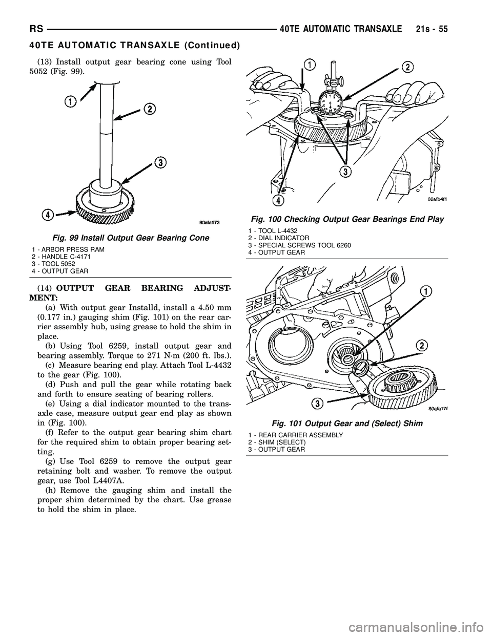
(13) Install output gear bearing cone using Tool
5052 (Fig. 99).
(14) OUTPUT GEAR BEARING ADJUST-
MENT: (a) With output gear Installd, install a 4.50 mm
(0.177 in.) gauging shim (Fig. 101) on the rear car-
rier assembly hub, using grease to hold the shim in
place. (b) Using Tool 6259, install output gear and
bearing assembly. Torque to 271 N´m (200 ft. lbs.). (c) Measure bearing end play. Attach Tool L-4432
to the gear (Fig. 100). (d) Push and pull the gear while rotating back
and forth to ensure seating of bearing rollers. (e) Using a dial indicator mounted to the trans-
axle case, measure output gear end play as shown
in (Fig. 100). (f) Refer to the output gear bearing shim chart
for the required shim to obtain proper bearing set-
ting. (g) Use Tool 6259 to remove the output gear
retaining bolt and washer. To remove the output
gear, use Tool L4407A. (h) Remove the gauging shim and install the
proper shim determined by the chart. Use grease
to hold the shim in place.
Fig. 99 Install Output Gear Bearing Cone
1 - ARBOR PRESS RAM
2 - HANDLE C-4171
3 - TOOL 5052
4 - OUTPUT GEAR
Fig. 100 Checking Output Gear Bearings End Play
1 - TOOL L-4432
2 - DIAL INDICATOR
3 - SPECIAL SCREWS TOOL 6260
4 - OUTPUT GEAR
Fig. 101 Output Gear and (Select) Shim
1 - REAR CARRIER ASSEMBLY
2 - SHIM (SELECT)
3 - OUTPUT GEAR
RS 40TE AUTOMATIC TRANSAXLE21s-55
40TE AUTOMATIC TRANSAXLE (Continued)