2004 CHRYSLER VOYAGER torque
[x] Cancel search: torquePage 1935 of 2585
(13) Install left and right halfshaft assemblies.
(Refer t o 3 - DIFFERENTIAL & DRIVELINE/HALF
SHAFT - INSTALLATION) (14) Install front wheel/tire assemblies.
(15) Lower vehicle.
(16) Torque remaining rear mount bracket-to-tran-
saxle vertical bolts (Fig. 160) to 102 N´m (75 ft. lbs.). (17) Install transaxle upper bellhousing-to-block
bolts and torque to 95 N´m (70 ft. lbs.). (18) Install and connect crank position sensor (if
equipped). (19) Connect gearshift cable to upper mount
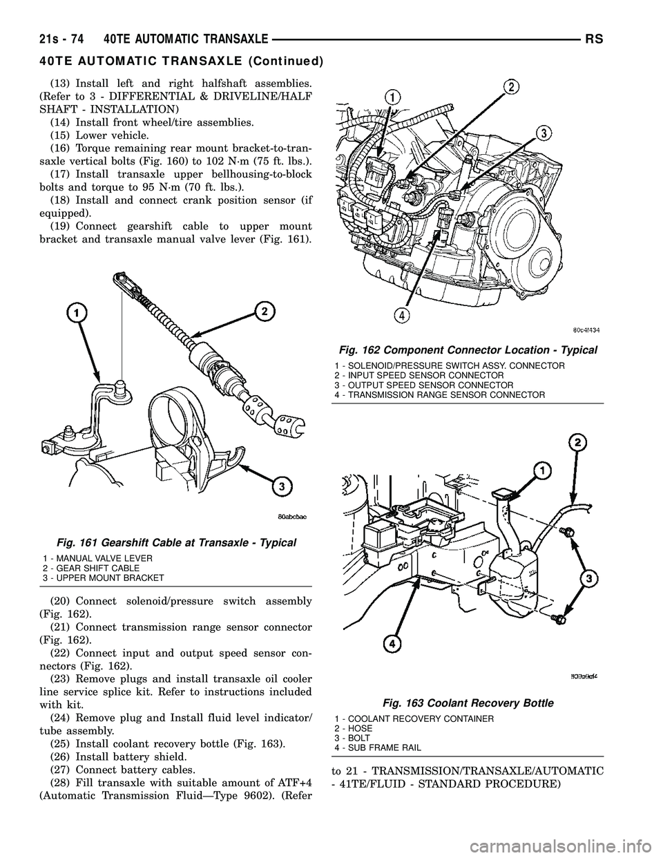
bracket and transaxle manual valve lever (Fig. 161).
(20) Connect solenoid/pressure switch assembly
(Fig. 162). (21) Connect transmission range sensor connector
(Fig. 162). (22) Connect input and output speed sensor con-
nectors (Fig. 162). (23) Remove plugs and install transaxle oil cooler
line service splice kit. Refer to instructions included
with kit. (24) Remove plug and Install fluid level indicator/
tube assembly. (25) Install coolant recovery bottle (Fig. 163).
(26) Install battery shield.
(27) Connect battery cables.
(28) Fill transaxle with suitable amount of ATF+4
(Automatic Transmission FluidÐType 9602). (Refer to 21 - TRANSMISSION/TRANSAXLE/AUTOMATIC
- 41TE/FLUID - STANDARD PROCEDURE)
Fig. 161 Gearshift Cable at Transaxle - Typical
1 - MANUAL VALVE LEVER
2 - GEAR SHIFT CABLE
3 - UPPER MOUNT BRACKET
Fig. 162 Component Connector Location - Typical
1 - SOLENOID/PRESSURE SWITCH ASSY. CONNECTOR
2 - INPUT SPEED SENSOR CONNECTOR
3 - OUTPUT SPEED SENSOR CONNECTOR
4 - TRANSMISSION RANGE SENSOR CONNECTOR
Fig. 163 Coolant Recovery Bottle
1 - COOLANT RECOVERY CONTAINER
2 - HOSE
3 - BOLT
4 - SUB FRAME RAIL
21s - 74 40TE AUTOMATIC TRANSAXLERS
40TE AUTOMATIC TRANSAXLE (Continued)
Page 1948 of 2585
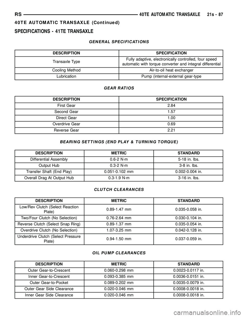
SPECIFICATIONS - 41TE TRANSAXLE
GENERAL SPECIFICATIONS
DESCRIPTION SPECIFICATION
Transaxle Type Fully adaptive, electronically controlled, four speed
automatic with torque converter and integral differential
Cooling Method Air-to-oil heat exchanger Lubrication Pump (internal-external gear-type
GEAR RATIOS
DESCRIPTION SPECIFICATION First Gear 2.84
Second Gear 1.57 Direct Gear 1.00
Overdrive Gear 0.69 Reverse Gear 2.21
BEARING SETTINGS (END PLAY & TURNING TORQUE)
DESCRIPTION METRIC STANDARD
Differential Assembly 0.6-2 N´m 5-18 in. lbs. Output Hub 0.3-2 N´m 3-8 in. lbs.
Transfer Shaft (End Play) 0.051-0.102 mm 0.002-0.004 in.
Overall Drag At Output Hub 0.3-1.9 N´m 3-16 in. lbs.
CLUTCH CLEARANCES
DESCRIPTION METRIC STANDARD
Low/Rev Clutch (Select Reaction Plate) 0.89-1.47 mm 0.035-0.058 in.
Two/Four Clutch (No Selection) 0.76-2.64 mm 0.030-0.104 in.
Reverse Clutch (Select Snap Ring) 0.89-1.37 mm 0.035-0.054 in. Overdrive Clutch (No Selection) 1.07-3.25 mm 0.042-0.128 in.
Underdrive Clutch (Select Pressure Plate) 0.94-1.50 mm 0.037-0.059 in.
OIL PUMP CLEARANCES
DESCRIPTION METRIC STANDARD
Outer Gear-to-Crescent 0.060-0.298 mm 0.0023-0.0117 in. Inner Gear-to-Crescent 0.093-0.385 mm 0.0036-0.0151 in. Outer Gear-to-Pocket 0.089-0.202 mm 0.0035-0.0079 in.
Outer Gear Side Clearance 0.020-0.046 mm 0.0008-0.0018 in. Inner Gear Side Clearance 0.020-0.046 mm 0.0008-0.0018 in.
RS 40TE AUTOMATIC TRANSAXLE21s-87
40TE AUTOMATIC TRANSAXLE (Continued)
Page 1949 of 2585
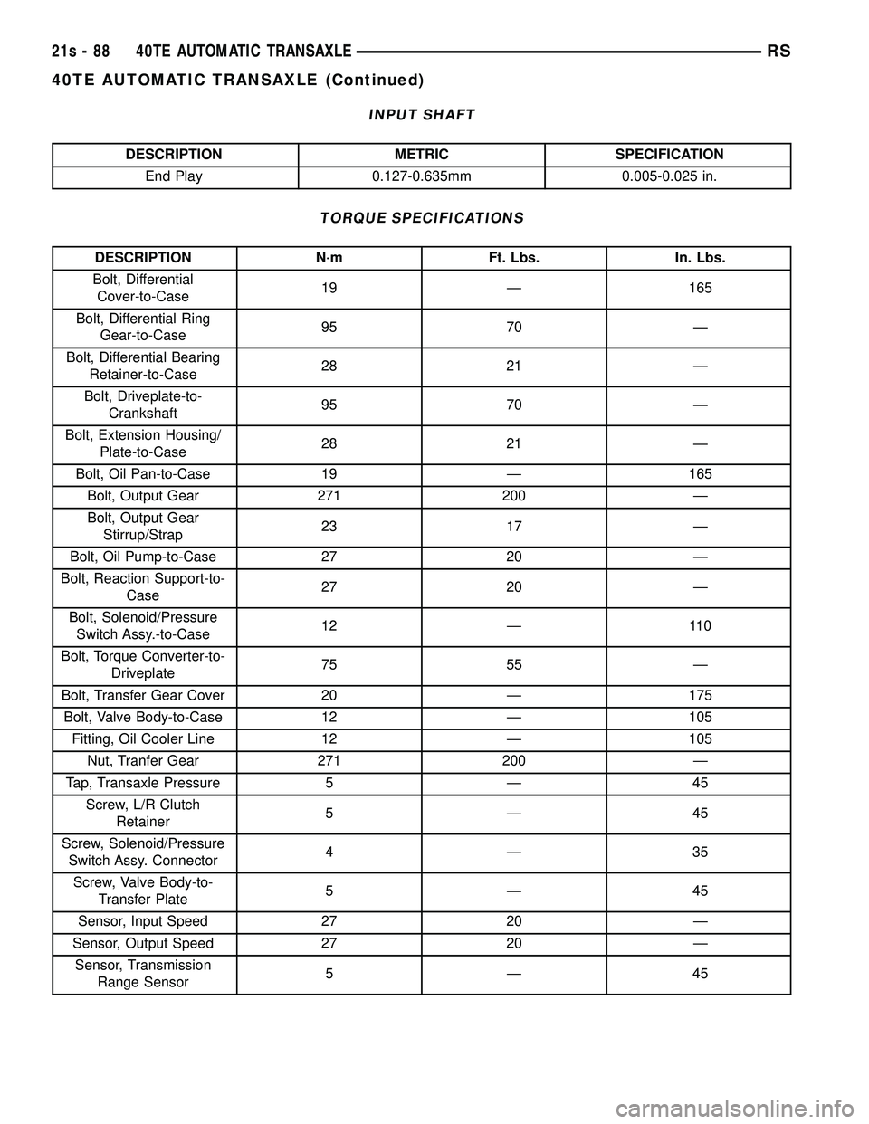
INPUT SHAFT
DESCRIPTION METRIC SPECIFICATIONEnd Play 0.127-0.635mm 0.005-0.025 in.
TORQUE SPECIFICATIONS
DESCRIPTION N´m Ft. Lbs. In. Lbs.
Bolt, Differential Cover-to-Case 19 Ð 165
Bolt, Differential Ring Gear-to-Case 95 70 Ð
Bolt, Differential Bearing Retainer-to-Case 28 21 Ð
Bolt, Driveplate-to- Crankshaft 95 70 Ð
Bolt, Extension Housing/ Plate-to-Case 28 21 Ð
Bolt, Oil Pan-to-Case 19 Ð 165 Bolt, Output Gear 271 200 Ð
Bolt, Output Gear Stirrup/Strap 23 17 Ð
Bolt, Oil Pump-to-Case 27 20 Ð
Bolt, Reaction Support-to- Case 27 20 Ð
Bolt, Solenoid/Pressure Switch Assy.-to-Case 12 Ð 110
Bolt, Torque Converter-to- Driveplate 75 55 Ð
Bolt, Transfer Gear Cover 20 Ð 175 Bolt, Valve Body-to-Case 12 Ð 105 Fitting, Oil Cooler Line 12 Ð 105 Nut, Tranfer Gear 271 200 Ð
Tap, Transaxle Pressure 5 Ð 45 Screw, L/R Clutch Retainer 5Ð45
Screw, Solenoid/Pressure Switch Assy. Connector 4Ð35
Screw, Valve Body-to- Transfer Plate 5Ð45
Sensor, Input Speed 27 20 Ð
Sensor, Output Speed 27 20 Ð Sensor, Transmission Range Sensor 5Ð45
21s - 88 40TE AUTOMATIC TRANSAXLERS
40TE AUTOMATIC TRANSAXLE (Continued)
Page 1957 of 2585
OPERATION
The differential assembly is driven by the transfer
shaft by way of the differential ring gear. The ring
gear drives the differential case, and the case drives
the driveshafts through the differential gears. The
differential pinion and side gears are supported in
the case by thrust washers and a pinion shaft. Dif-
ferential pinion and side gears make it possible for
front tires to rotate at different speeds while corner-
ing.
DISASSEMBLY
NOTE: The differential is serviced as an assembly.
The only parts that are serviceable within the differ-
ential are the differential bearing cups and cones. If
any other part fails within the differential, you must
replace the differential assembly along with the
transfer shaft.
The transfer shaft should be removed for differen-
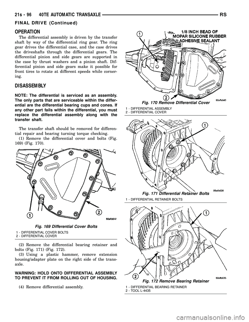
tial repair and bearing turning torque checking. (1) Remove the differential cover and bolts (Fig.
169) (Fig. 170).
(2) Remove the differential bearing retainer and
bolts (Fig. 171) (Fig. 172). (3) Using a plastic hammer, remove extension
housing/adapter plate on the right side of the trans-
axle.
WARNING: HOLD ONTO DIFFERENTIAL ASSEMBLY
TO PREVENT IT FROM ROLLING OUT OF HOUSING.
(4) Remove differential assembly.
Fig. 169 Differential Cover Bolts
1 - DIFFERENTIAL COVER BOLTS
2 - DIFFERENTIAL COVER
Fig. 170 Remove Differential Cover
1 - DIFFERENTIAL ASSEMBLY
2 - DIFFERENTIAL COVER
Fig. 171 Differential Retainer Bolts
1 - DIFFERENTIAL RETAINER BOLTS
Fig. 172 Remove Bearing Retainer
1 - DIFFERENTIAL BEARING RETAINER
2 - TOOL L-4435
21s - 96 40TE AUTOMATIC TRANSAXLERS
FINAL DRIVE (Continued)
Page 1960 of 2585
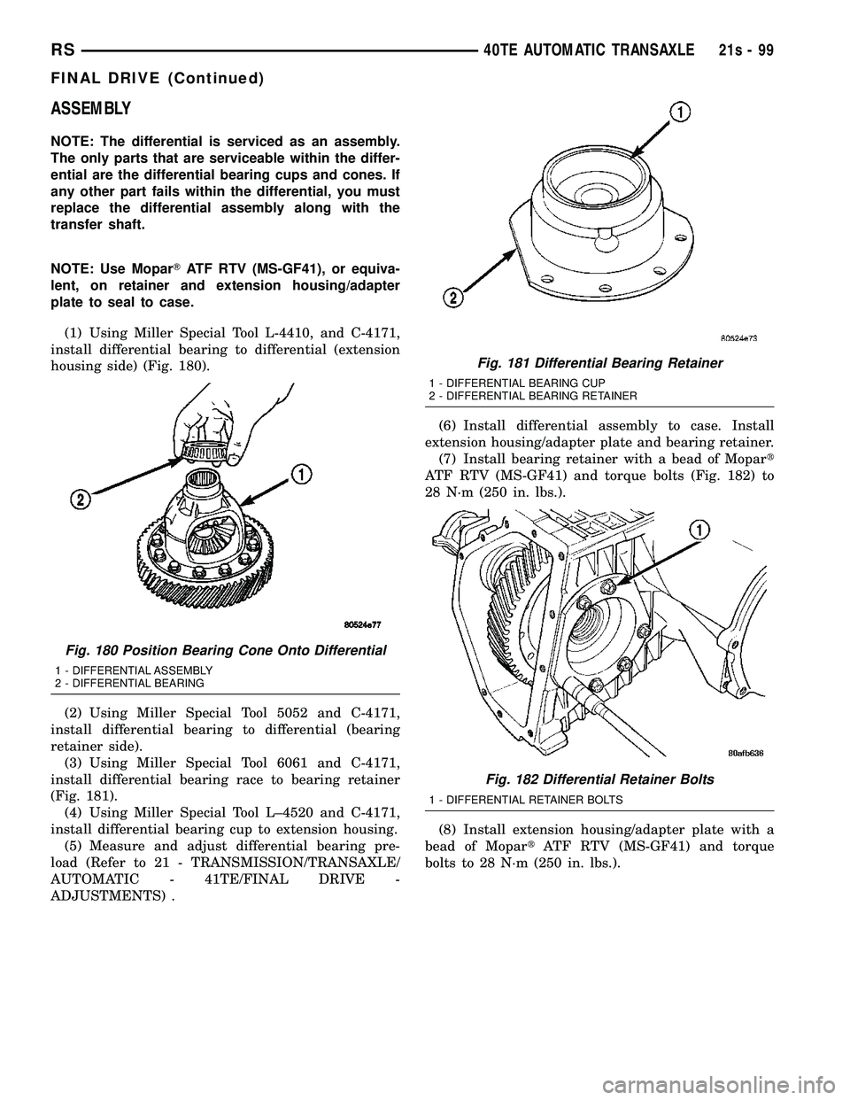
ASSEMBLY
NOTE: The differential is serviced as an assembly.
The only parts that are serviceable within the differ-
ential are the differential bearing cups and cones. If
any other part fails within the differential, you must
replace the differential assembly along with the
transfer shaft.
NOTE: Use MoparTATF RTV (MS-GF41), or equiva-
lent, on retainer and extension housing/adapter
plate to seal to case.
(1) Using Miller Special Tool L-4410, and C-4171,
install differential bearing to differential (extension
housing side) (Fig. 180).
(2) Using Miller Special Tool 5052 and C-4171,
install differential bearing to differential (bearing
retainer side). (3) Using Miller Special Tool 6061 and C-4171,
install differential bearing race to bearing retainer
(Fig. 181). (4) Using Miller Special Tool L±4520 and C-4171,
install differential bearing cup to extension housing. (5) Measure and adjust differential bearing pre-
load (Refer to 21 - TRANSMISSION/TRANSAXLE/
AUTOMATIC - 41TE/FINAL DRIVE -
ADJUSTMENTS) . (6) Install differential assembly to case. Install
extension housing/adapter plate and bearing retainer. (7) Install bearing retainer with a bead of Mopar t
ATF RTV (MS-GF41) and torque bolts (Fig. 182) to
28 N´m (250 in. lbs.).
(8) Install extension housing/adapter plate with a
bead of Mopar tATF RTV (MS-GF41) and torque
bolts to 28 N´m (250 in. lbs.).
Fig. 180 Position Bearing Cone Onto Differential
1 - DIFFERENTIAL ASSEMBLY
2 - DIFFERENTIAL BEARING
Fig. 181 Differential Bearing Retainer
1 - DIFFERENTIAL BEARING CUP
2 - DIFFERENTIAL BEARING RETAINER
Fig. 182 Differential Retainer Bolts
1 - DIFFERENTIAL RETAINER BOLTS
RS 40TE AUTOMATIC TRANSAXLE21s-99
FINAL DRIVE (Continued)
Page 1961 of 2585
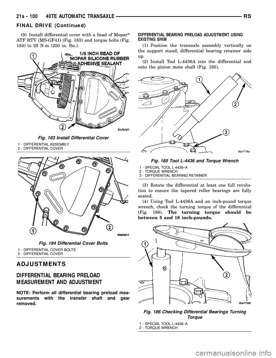
(9) Install differential cover with a bead of Mopart
ATF RTV (MS-GF41) (Fig. 183) and torque bolts (Fig.
184) to 28 N´m (250 in. lbs.).
ADJUSTMENTS
DIFFERENTIAL BEARING PRELOAD
MEASUREMENT AND ADJUSTMENT
NOTE: Perform all differential bearing preload mea-
surements with the transfer shaft and gear
removed. DIFFERENTIAL BEARING PRELOAD ADJUSTMENT USING
EXISTING SHIM
(1) Position the transaxle assembly vertically on
the support stand, differential bearing retainer side
up. (2) Install Tool L-4436A into the differential and
onto the pinion mate shaft (Fig. 185).
(3) Rotate the differential at least one full revolu-
tion to ensure the tapered roller bearings are fully
seated. (4) Using Tool L-4436A and an inch-pound torque
wrench, check the turning torque of the differential
(Fig. 186). The turning torque should be
between 5 and 18 inch-pounds.
Fig. 183 Install Differential Cover
1 - DIFFERENTIAL ASSEMBLY
2 - DIFFERENTIAL COVER
Fig. 184 Differential Cover Bolts
1 - DIFFERENTIAL COVER BOLTS
2 - DIFFERENTIAL COVER
Fig. 185 Tool L-4436 and Torque Wrench
1 - SPECIAL TOOL L-4436±A
2 - TORQUE WRENCH
3 - DIFFERENTIAL BEARING RETAINER
Fig. 186 Checking Differential Bearings Turning Torque
1 - SPECIAL TOOL L-4436±A
2 - TORQUE WRENCH
21s - 100 40TE AUTOMATIC TRANSAXLERS
FINAL DRIVE (Continued)
Page 1962 of 2585
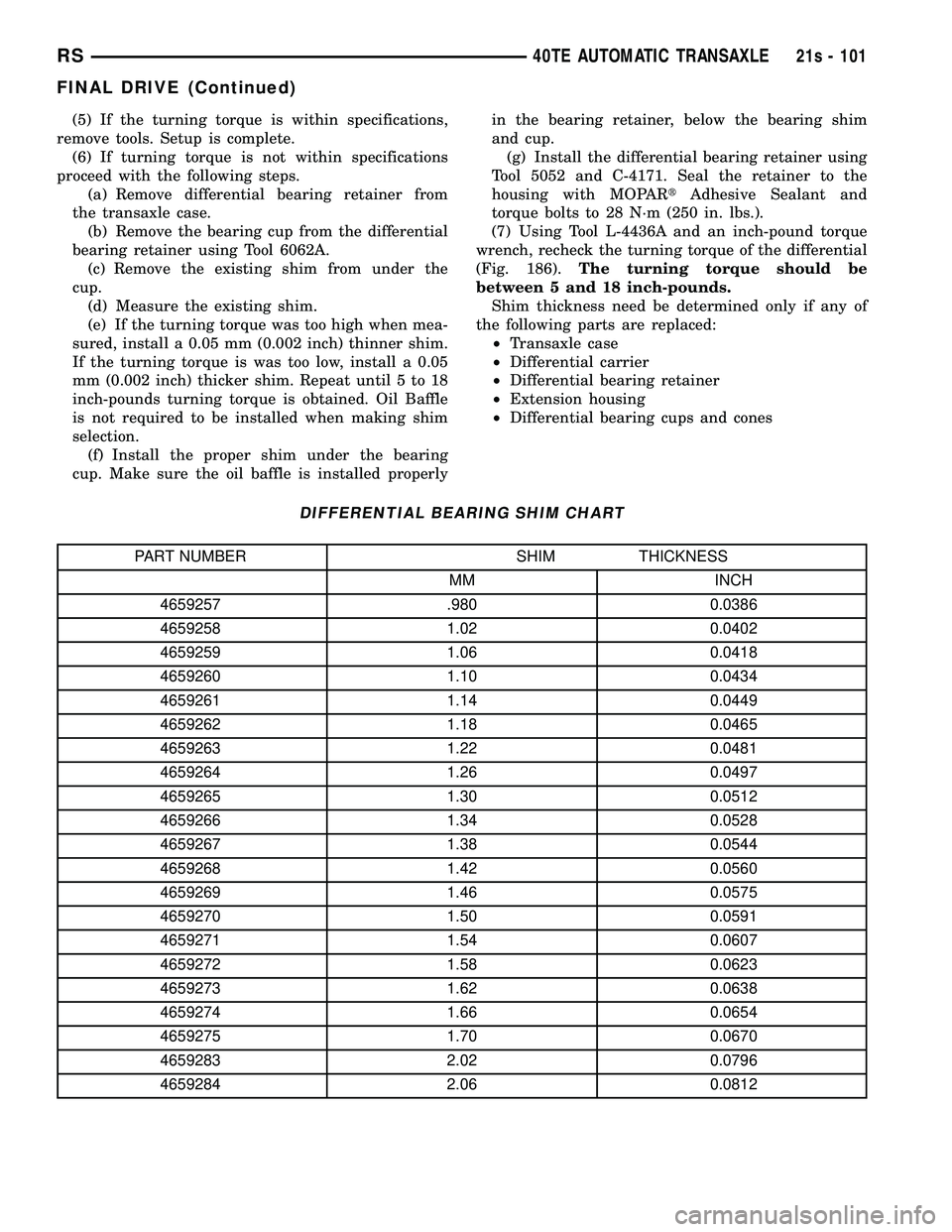
(5) If the turning torque is within specifications,
remove tools. Setup is complete. (6) If turning torque is not within specifications
proceed with the following steps. (a) Remove differential bearing retainer from
the transaxle case. (b) Remove the bearing cup from the differential
bearing retainer using Tool 6062A. (c) Remove the existing shim from under the
cup. (d) Measure the existing shim.
(e) If the turning torque was too high when mea-
sured, install a 0.05 mm (0.002 inch) thinner shim.
If the turning torque is was too low, install a 0.05
mm (0.002 inch) thicker shim. Repeat until 5 to 18
inch-pounds turning torque is obtained. Oil Baffle
is not required to be installed when making shim
selection. (f) Install the proper shim under the bearing
cup. Make sure the oil baffle is installed properly in the bearing retainer, below the bearing shim
and cup.
(g) Install the differential bearing retainer using
Tool 5052 and C-4171. Seal the retainer to the
housing with MOPAR tAdhesive Sealant and
torque bolts to 28 N´m (250 in. lbs.).
(7) Using Tool L-4436A and an inch-pound torque
wrench, recheck the turning torque of the differential
(Fig. 186). The turning torque should be
between 5 and 18 inch-pounds. Shim thickness need be determined only if any of
the following parts are replaced: ² Transaxle case
² Differential carrier
² Differential bearing retainer
² Extension housing
² Differential bearing cups and cones
DIFFERENTIAL BEARING SHIM CHART
PART NUMBER SHIM THICKNESS
MM INCH
4659257 .980 0.0386
4659258 1.02 0.0402
4659259 1.06 0.0418
4659260 1.10 0.0434
4659261 1.14 0.0449
4659262 1.18 0.0465
4659263 1.22 0.0481
4659264 1.26 0.0497
4659265 1.30 0.0512
4659266 1.34 0.0528
4659267 1.38 0.0544
4659268 1.42 0.0560
4659269 1.46 0.0575
4659270 1.50 0.0591
4659271 1.54 0.0607
4659272 1.58 0.0623
4659273 1.62 0.0638
4659274 1.66 0.0654
4659275 1.70 0.0670
4659283 2.02 0.0796
4659284 2.06 0.0812
RS 40TE AUTOMATIC TRANSAXLE21s - 101
FINAL DRIVE (Continued)
Page 1963 of 2585
PRELOAD ADJUSTMENT W/O SHIM(1) Remove the bearing cup from the differential
bearing retainer using Miller special Tool 6062A. (2) Remove existing shim from under bearing cup.
(3) Reinstall the bearing cup into the retainer
using Miller Special Tool 6061, and C-4171.
NOTE: Oil baffle is not required when making the
shim calculation.
(4) Install the bearing retainer into the case.
Torque bolts to 28 N ²m (250 in. lbs.).
(5) Position the transaxle assembly vertically on
the support stand and install Miller Special Tool
L-4436-A into the bearing retainer. (6) Rotate the differential at least one full revolu-
tion to ensure the tapered roller bearings are fully
seated. (7) Attach a dial indicator to the case and zero the
dial. Place the tip on the end of Special Tool
L-4436-A. (8) Place a large screwdriver to each side of the
ring gear and lift. Check the dial indicator for the
amount of end play.
CAUTION: Do not damage the transaxle case and/or
differential retainer sealing surface.
(9) Using the end play measurement that was
determined, add 0.18mm (0.007 inch). This should
give you between 5 and 18 inch pounds of bearing
preload. Refer to the Differential Bearing Shim Chart
to determine which shim to use. (10) Remove the differential bearing retainer.
Remove the bearing cup. (11) Install the oil baffle. Install the proper shim
combination under the bearing cup. (12) Install the differential bearing retainer. Seal
the retainer to the housing with Mopar tSilicone
Rubber Adhesive Sealant. Torque bolts to 28 N ²m
(250 in. lbs.). (13) Using Miller Special Tool L-4436-A and an
inch-pound torque wrench, check the turning torque
of the differential (Fig. 186). The turning torque
should be between 5-18 inch-pounds.
NOTE: If turning torque is too high install a 0.05mm
(0.002 inch) thicker shim. If the turning torque is too
low, install a 0.05mm (0.002 inch) thinner shim.
Repeat until 5-18 inch-pounds of turning torque is
obtained.FLUID
STANDARD PROCEDURE
FLUID LEVEL AND CONDITION CHECK
NOTE: Only transmission fluid of the type labeled
Mopar ATF+4 (Automatic Transmission Fluid)
should be used in this transaxle.
FLUID LEVEL CHECK
The transmission sump has a fluid level indicator
(dipstick) to check oil similar to most automatic
transmissions. It is located on the left side of the
engine. Be sure to wipe all dirt from dipstick handle
before removing. The torque converter fills in both the P Park and N
Neutral positions. Place the selector lever in P Park
to be sure that the fluid level check is accurate. The
engine should be running at idle speed for at
least one minute, with the vehicle on level
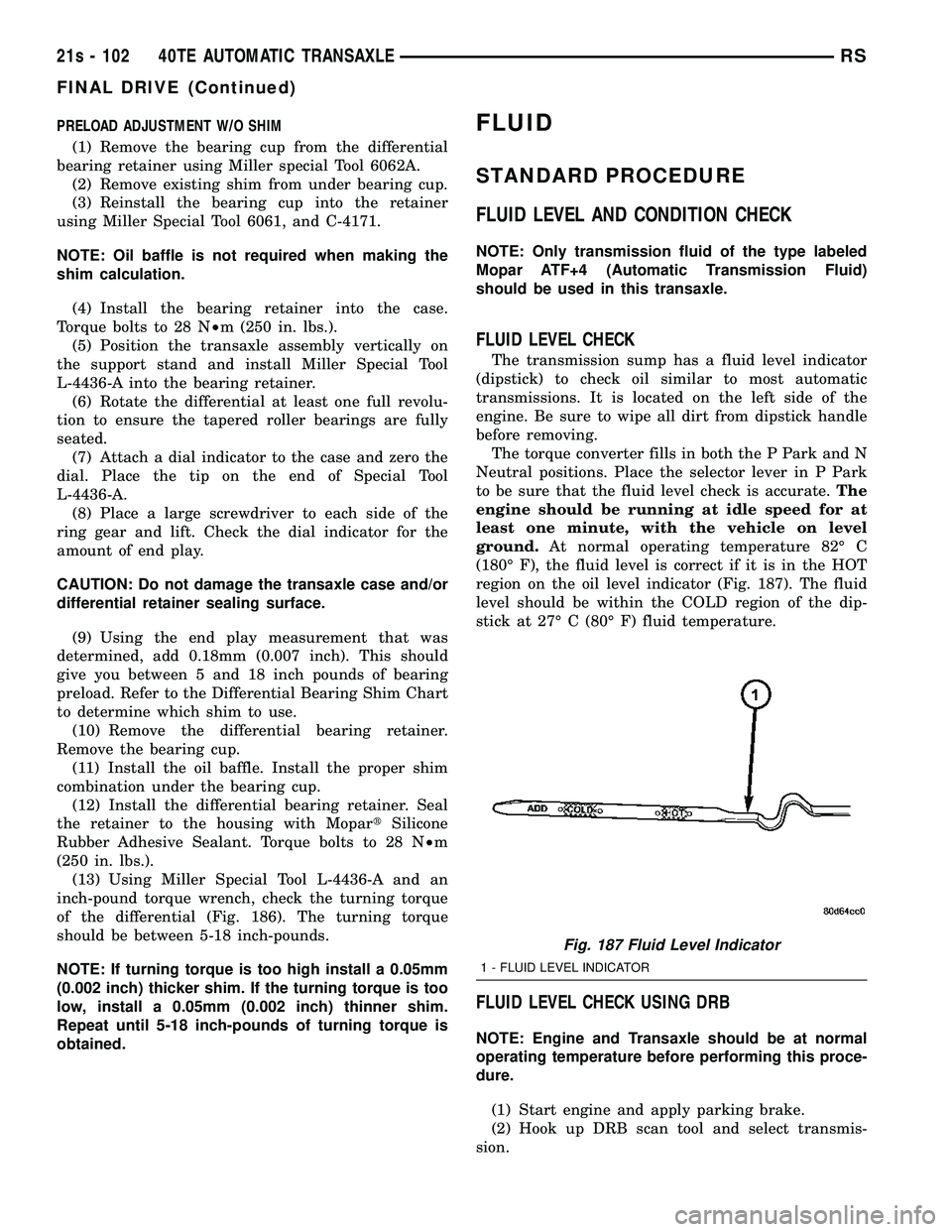
ground. At normal operating temperature 82É C
(180É F), the fluid level is correct if it is in the HOT
region on the oil level indicator (Fig. 187). The fluid
level should be within the COLD region of the dip-
stick at 27É C (80É F) fluid temperature.
FLUID LEVEL CHECK USING DRB
NOTE: Engine and Transaxle should be at normal
operating temperature before performing this proce-
dure.
(1) Start engine and apply parking brake.
(2) Hook up DRB scan tool and select transmis-
sion.
Fig. 187 Fluid Level Indicator
1 - FLUID LEVEL INDICATOR
21s - 102 40TE AUTOMATIC TRANSAXLERS
FINAL DRIVE (Continued)