Page 1760 of 2585
(57) Install oil pump assembly (Fig. 149).
(58) Install oil pump-to-case bolts and torque to 27
N´m (20 ft. lbs.) (Fig. 150).(59) Install low/reverse accumulator (Fig. 151).
(60) Install low/reverse accumulator plug (Fig.
152).
Fig. 149 Install Oil Pump
1 - OIL PUMP
2 - GASKET
Fig. 150 Install Pump-to-Case Bolts
1 - PUMP ATTACHING BOLTS
2 - PUMP HOUSING
Fig. 151 Install Low/Reverse Accumulator
1 - ACCUMULATOR PISTON
2 - SEAL RINGS
3 - RETURN SPRINGS
4 - (NOTE NOTCH)
Fig. 152 Install Low/Reverse Accumulator Plug
(Cover)
1 - ADJUSTABLE PLIERS
2 - PLUG
RS41TE AUTOMATIC TRANSAXLE21 - 163
41TE AUTOMATIC TRANSAXLE (Continued)
Page 1762 of 2585
(63) Install valve body to transaxle (Fig. 157).
Rotate manual valve shaft fully clockwise to ease
installation. Make sure park rod rollers are posi-
tioned within park guide bracket.
(64) Install and torque valve body-to-case bolts to
12 N´m (105 in. lbs.) (Fig. 158).(65) Install oil filter and new o-ring (Fig. 159).
(66) Apply an 1/8º bead of MopartATF RTV (MS-
GF41) to oil pan and immediately install to case (Fig.
160).
Fig. 157 Install Valve Body
1 - VALVE BODY
Fig. 158 Install Valve Body-to-Case Bolts
1 - VALVE BODY ATTACHING BOLTS (18)
2 - VALVE BODY
Fig. 159 Install Oil Filter
1 - OIL FILTER
2 - O-RING
Fig. 160 Install Oil Pan
1 - OIL PAN
2 - 1/8 INCH BEAD OF MOPARTATF RTV (MS-GF41)
3 - OIL FILTER
RS41TE AUTOMATIC TRANSAXLE21 - 165
41TE AUTOMATIC TRANSAXLE (Continued)
Page 1763 of 2585

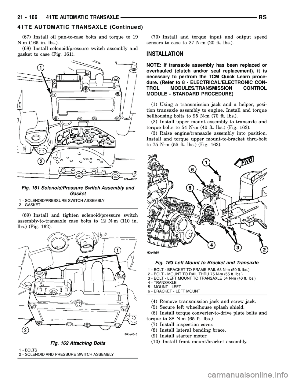
(67) Install oil pan-to-case bolts and torque to 19
N´m (165 in. lbs.).
(68) Install solenoid/pressure switch assembly and
gasket to case (Fig. 161).
(69) Install and tighten solenoid/pressure switch
assembly-to-transaxle case bolts to 12 N´m (110 in.
lbs.) (Fig. 162).(70) Install and torque input and output speed
sensors to case to 27 N´m (20 ft. lbs.).
INSTALLATION
NOTE: If transaxle assembly has been replaced or
overhauled (clutch and/or seal replacement), it is
necessary to perfrom the TCM Quick Learn proce-
dure. (Refer to 8 - ELECTRICAL/ELECTRONIC CON-
TROL MODULES/TRANSMISSION CONTROL
MODULE - STANDARD PROCEDURE)
(1) Using a transmission jack and a helper, posi-
tion transaxle assembly to engine. Install and torque
bellhousing bolts to 95 N´m (70 ft. lbs.).
(2) Install upper mount assembly to transaxle and
torque bolts to 54 N´m (40 ft. lbs.) (Fig. 163).
(3) Raise engine/transaxle assembly into position.
Install and torque upper mount-to-bracket thru-bolt
to 75 N´m (55 ft. lbs.) (Fig. 163).
(4) Remove transmission jack and screw jack.
(5) Secure left wheelhouse splash shield.
(6) Install torque converter-to-drive plate bolts and
torque to 88 N´m (65 ft. lbs.)
(7) Install inspection cover.
(8) Install lateral bending brace.
(9) Install starter motor.
(10) Install front mount/bracket assembly.
Fig. 161 Solenoid/Pressure Switch Assembly and
Gasket
1 - SOLENOID/PRESSURE SWITCH ASSEMBLY
2 - GASKET
Fig. 162 Attaching Bolts
1 - BOLTS
2 - SOLENOID AND PRESSURE SWITCH ASSEMBLY
Fig. 163 Left Mount to Bracket and Transaxle
1 - BOLT - BRACKET TO FRAME RAIL 68 N´m (50 ft. lbs.)
2 - BOLT - MOUNT TO RAIL THRU 75 N´m (55 ft. lbs.)
3 - BOLT - LEFT MOUNT TO TRANSAXLE 54 N´m (40 ft. lbs.)
4 - TRANSAXLE
5 - MOUNT - LEFT
6 - BRACKET - LEFT MOUNT
21 - 166 41TE AUTOMATIC TRANSAXLERS
41TE AUTOMATIC TRANSAXLE (Continued)
Page 1764 of 2585

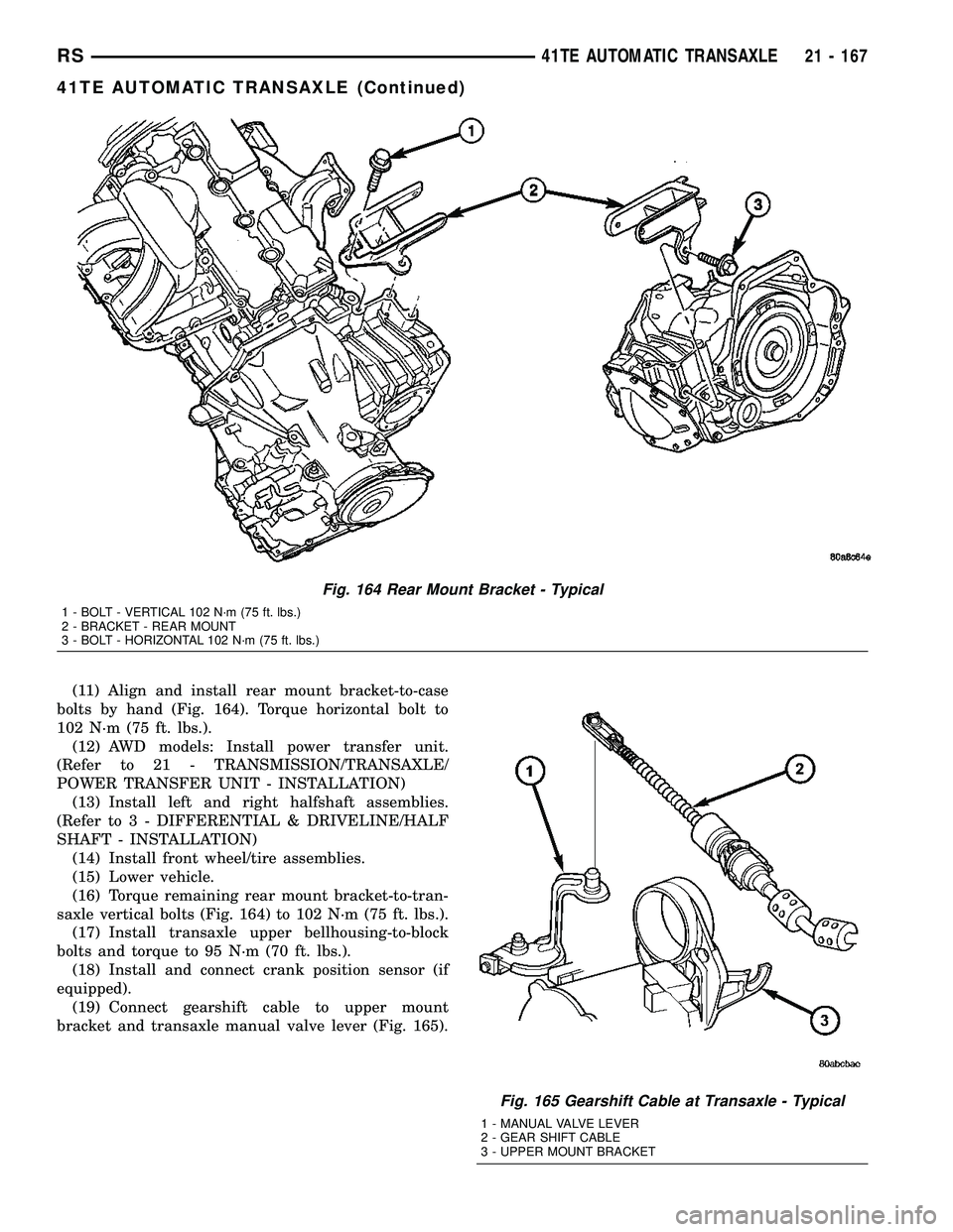
(11) Align and install rear mount bracket-to-case
bolts by hand (Fig. 164). Torque horizontal bolt to
102 N´m (75 ft. lbs.).
(12) AWD models: Install power transfer unit.
(Refer to 21 - TRANSMISSION/TRANSAXLE/
POWER TRANSFER UNIT - INSTALLATION)
(13) Install left and right halfshaft assemblies.
(Refer to 3 - DIFFERENTIAL & DRIVELINE/HALF
SHAFT - INSTALLATION)
(14) Install front wheel/tire assemblies.
(15) Lower vehicle.
(16) Torque remaining rear mount bracket-to-tran-
saxle vertical bolts (Fig. 164) to 102 N´m (75 ft. lbs.).
(17) Install transaxle upper bellhousing-to-block
bolts and torque to 95 N´m (70 ft. lbs.).
(18) Install and connect crank position sensor (if
equipped).
(19) Connect gearshift cable to upper mount
bracket and transaxle manual valve lever (Fig. 165).
Fig. 164 Rear Mount Bracket - Typical
1 - BOLT - VERTICAL 102 N´m (75 ft. lbs.)
2 - BRACKET - REAR MOUNT
3 - BOLT - HORIZONTAL 102 N´m (75 ft. lbs.)
Fig. 165 Gearshift Cable at Transaxle - Typical
1 - MANUAL VALVE LEVER
2 - GEAR SHIFT CABLE
3 - UPPER MOUNT BRACKET
RS41TE AUTOMATIC TRANSAXLE21 - 167
41TE AUTOMATIC TRANSAXLE (Continued)
Page 1778 of 2585

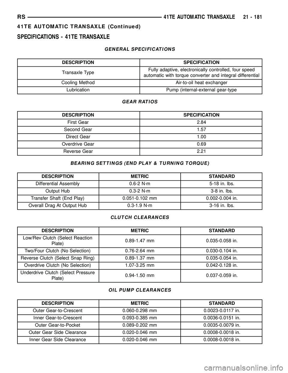
SPECIFICATIONS - 41TE TRANSAXLE
GENERAL SPECIFICATIONS
DESCRIPTION SPECIFICATION
Transaxle TypeFully adaptive, electronically controlled, four speed
automatic with torque converter and integral differential
Cooling Method Air-to-oil heat exchanger
Lubrication Pump (internal-external gear-type
GEAR RATIOS
DESCRIPTION SPECIFICATION
First Gear 2.84
Second Gear 1.57
Direct Gear 1.00
Overdrive Gear 0.69
Reverse Gear 2.21
BEARING SETTINGS (END PLAY & TURNING TORQUE)
DESCRIPTION METRIC STANDARD
Differential Assembly 0.6-2 N´m 5-18 in. lbs.
Output Hub 0.3-2 N´m 3-8 in. lbs.
Transfer Shaft (End Play) 0.051-0.102 mm 0.002-0.004 in.
Overall Drag At Output Hub 0.3-1.9 N´m 3-16 in. lbs.
CLUTCH CLEARANCES
DESCRIPTION METRIC STANDARD
Low/Rev Clutch (Select Reaction
Plate)0.89-1.47 mm 0.035-0.058 in.
Two/Four Clutch (No Selection) 0.76-2.64 mm 0.030-0.104 in.
Reverse Clutch (Select Snap Ring) 0.89-1.37 mm 0.035-0.054 in.
Overdrive Clutch (No Selection) 1.07-3.25 mm 0.042-0.128 in.
Underdrive Clutch (Select Pressure
Plate)0.94-1.50 mm 0.037-0.059 in.
OIL PUMP CLEARANCES
DESCRIPTION METRIC STANDARD
Outer Gear-to-Crescent 0.060-0.298 mm 0.0023-0.0117 in.
Inner Gear-to-Crescent 0.093-0.385 mm 0.0036-0.0151 in.
Outer Gear-to-Pocket 0.089-0.202 mm 0.0035-0.0079 in.
Outer Gear Side Clearance 0.020-0.046 mm 0.0008-0.0018 in.
Inner Gear Side Clearance 0.020-0.046 mm 0.0008-0.0018 in.
RS41TE AUTOMATIC TRANSAXLE21 - 181
41TE AUTOMATIC TRANSAXLE (Continued)
Page 1779 of 2585

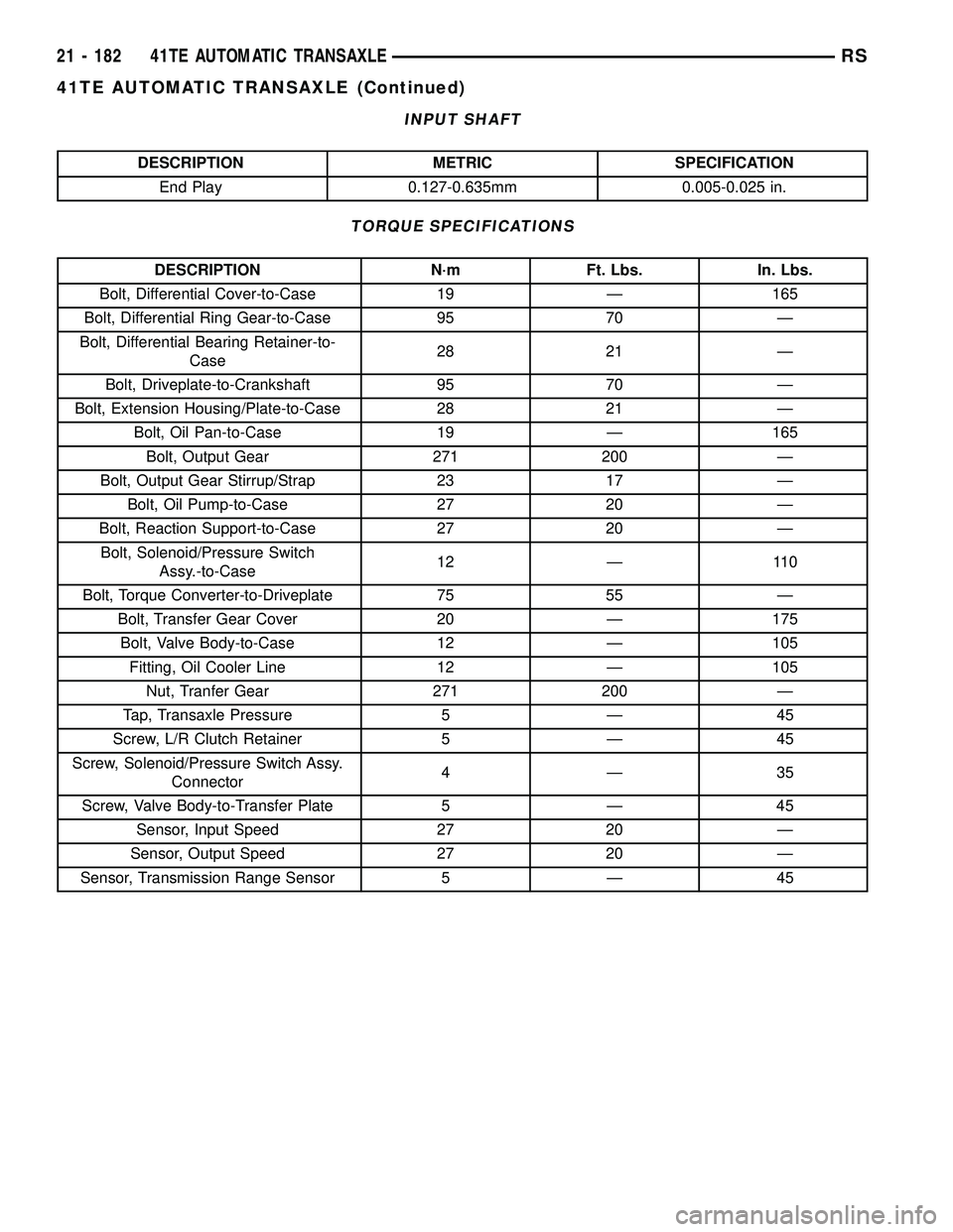
INPUT SHAFT
DESCRIPTION METRIC SPECIFICATION
End Play 0.127-0.635mm 0.005-0.025 in.
TORQUE SPECIFICATIONS
DESCRIPTION N´m Ft. Lbs. In. Lbs.
Bolt, Differential Cover-to-Case 19 Ð 165
Bolt, Differential Ring Gear-to-Case 95 70 Ð
Bolt, Differential Bearing Retainer-to-
Case28 21 Ð
Bolt, Driveplate-to-Crankshaft 95 70 Ð
Bolt, Extension Housing/Plate-to-Case 28 21 Ð
Bolt, Oil Pan-to-Case 19 Ð 165
Bolt, Output Gear 271 200 Ð
Bolt, Output Gear Stirrup/Strap 23 17 Ð
Bolt, Oil Pump-to-Case 27 20 Ð
Bolt, Reaction Support-to-Case 27 20 Ð
Bolt, Solenoid/Pressure Switch
Assy.-to-Case12 Ð 110
Bolt, Torque Converter-to-Driveplate 75 55 Ð
Bolt, Transfer Gear Cover 20 Ð 175
Bolt, Valve Body-to-Case 12 Ð 105
Fitting, Oil Cooler Line 12 Ð 105
Nut, Tranfer Gear 271 200 Ð
Tap, Transaxle Pressure 5 Ð 45
Screw, L/R Clutch Retainer 5 Ð 45
Screw, Solenoid/Pressure Switch Assy.
Connector4Ð35
Screw, Valve Body-to-Transfer Plate 5 Ð 45
Sensor, Input Speed 27 20 Ð
Sensor, Output Speed 27 20 Ð
Sensor, Transmission Range Sensor 5 Ð 45
21 - 182 41TE AUTOMATIC TRANSAXLERS
41TE AUTOMATIC TRANSAXLE (Continued)
Page 1788 of 2585
The transfer shaft should be removed for differen-
tial repair and bearing turning torque checking.
(1) Remove the differential cover and bolts (Fig.
173) (Fig. 174).(2) Remove the differential bearing retainer and
bolts (Fig. 175) (Fig. 176).
(3) Using a plastic hammer, remove extension
housing/adapter plate on the right side of the trans-
axle.
WARNING: HOLD ONTO DIFFERENTIAL ASSEMBLY
TO PREVENT IT FROM ROLLING OUT OF HOUSING.
Fig. 173 Differential Cover Bolts
1 - DIFFERENTIAL COVER BOLTS
2 - DIFFERENTIAL COVER
Fig. 174 Remove Differential Cover
1 - DIFFERENTIAL ASSEMBLY
2 - DIFFERENTIAL COVER
Fig. 175 Differential Retainer Bolts
1 - DIFFERENTIAL RETAINER BOLTS
Fig. 176 Remove Bearing Retainer
1 - DIFFERENTIAL BEARING RETAINER
2 - TOOL L-4435
RS41TE AUTOMATIC TRANSAXLE21 - 191
FINAL DRIVE (Continued)
Page 1794 of 2585
(6) Install side gear thrust washer to case (Fig.
197).
(7) Install differential support into position, while
aligning through-holes (Fig. 198).(8) Install differential ring gear to case (Fig. 199).
(9) Install ring gear-to-case bolts, with pinion shaft
retainers (Fig. 200), and torque bolts to 95 N´m (70
ft. lbs.).
Fig. 197 Side Gear Thrust Washer
1 - SIDE GEAR THRUST WASHER
Fig. 198 Diff Support Installation
1 - DIFFERENTIAL SUPPORT
2 - DIFFERENTIAL CASE
Fig. 199 Ring Gear Installation
1 - DIFFERENTIAL CASE
2 - RING GEAR
Fig. 200 Ring Gear-to-Case Bolts
1 - DIFFERENTIAL CASE
2 - PINION SHAFT RETAINER
3 - RING GEAR
4 - RING GEAR-TO-CASE BOLT
RS41TE AUTOMATIC TRANSAXLE21 - 197
FINAL DRIVE (Continued)