2004 CHRYSLER VOYAGER light
[x] Cancel search: lightPage 1526 of 2585
1 second. Therefore, battery voltage is not supplied to
the fuel pump, ignition coil, fuel injectors and heated
oxygen sensors.
ENGINE START-UP MODE
This is an OPEN LOOP mode. If the vehicle is in
park or neutral (automatic transaxles) or the clutch
pedal is depressed (manual transaxles) the ignition
switch energizes the starter relay when the engine is
not running. The following actions occur when the
starter motor is engaged.
²If the PCM receives the camshaft position sensor
and crankshaft position sensor signals, it energizes
the Auto Shutdown (ASD) relay and fuel pump relay.
If the PCM does not receive both signals within
approximately one second, it will not energize the
ASD relay and fuel pump relay. The ASD and fuel
pump relays supply battery voltage to the fuel pump,
fuel injectors, ignition coil, (EGR solenoid and PCV
heater if equipped) and heated oxygen sensors.
²The PCM energizes the injectors (on the 69É
degree falling edge) for a calculated pulse width until
it determines crankshaft position from the camshaft
position sensor and crankshaft position sensor sig-
nals. The PCM determines crankshaft position within
1 engine revolution.
²After determining crankshaft position, the PCM
begins energizing the injectors in sequence. It adjusts
injector pulse width and controls injector synchroni-
zation by turning the individual ground paths to the
injectors On and Off.
²When the engine idles within 64 RPM of its
target RPM, the PCM compares current MAP sensor
value with the atmospheric pressure value received
during the Ignition Switch On (zero RPM) mode.
Once the ASD and fuel pump relays have been
energized, the PCM determines injector pulse width
based on the following:
²MAP
²Engine RPM
²Battery voltage
²Engine coolant temperature
²Inlet/Intake air temperature (IAT)
²Throttle position
²The number of engine revolutions since cranking
was initiated
During Start-up the PCM maintains ignition tim-
ing at 9É BTDC.
ENGINE WARM-UP MODE
This is an OPEN LOOP mode. The following inputs
are received by the PCM:
²Manifold Absolute Pressure (MAP)
²Crankshaft position (engine speed)
²Engine coolant temperature
²Inlet/Intake air temperature (IAT)²Camshaft position
²Knock sensor
²Throttle position
²A/C switch status
²Battery voltage
²Vehicle speed
²Speed control
²O2 sensors
The PCM adjusts injector pulse width and controls
injector synchronization by turning the individual
ground paths to the injectors On and Off.
The PCM adjusts ignition timing and engine idle
speed. Engine idle speed is adjusted through the idle
air control motor.
CRUISE OR IDLE MODE
When the engine is at operating temperature this
is a CLOSED LOOP mode. During cruising or idle
the following inputs are received by the PCM:
²Manifold absolute pressure
²Crankshaft position (engine speed)
²Inlet/Intake air temperature
²Engine coolant temperature
²Camshaft position
²Knock sensor
²Throttle position
²Exhaust gas oxygen content (O2 sensors)
²A/C switch status
²Battery voltage
²Vehicle speed
The PCM adjusts injector pulse width and controls
injector synchronization by turning the individual
ground paths to the injectors On and Off.
The PCM adjusts engine idle speed and ignition
timing. The PCM adjusts the air/fuel ratio according
to the oxygen content in the exhaust gas (measured
by the upstream and downstream heated oxygen sen-
sor).
The PCM monitors for engine misfire. During
active misfire and depending on the severity, the
PCM either continuously illuminates or flashes the
malfunction indicator lamp (Check Engine light on
instrument panel). Also, the PCM stores an engine
misfire DTC in memory, if 2nd trip with fault.
The PCM performs several diagnostic routines.
They include:
²Oxygen sensor monitor
²Downstream heated oxygen sensor diagnostics
during open loop operation (except for shorted)
²Fuel system monitor
²EGR monitor (if equipped)
²Purge system monitor
²Catalyst efficiency monitor
²All inputs monitored for proper voltage range,
rationality.
RSFUEL INJECTION14-19
FUEL INJECTION (Continued)
Page 1536 of 2585
The PCM controls engine idle speed by adjusting
the position of the idle air control valve. The adjust-
ments are based on inputs the PCM receives. The
inputs are from the throttle position sensor, crank-
shaft position sensor, coolant temperature sensor,
MAP sensor, vehicle speed sensor and various switch
operations (brake, park/neutral, air conditioning).
When engine rpm is above idle speed, the IAC is
used for the following functions:
²Off-idle dashpot
²Deceleration air flow control²A/C compressor load control (also opens the pas-
sage slightly before the compressor is engaged so
that the engine rpm does not dip down when the
compressor engages)
Target Idle
Target idle is determined by the following inputs:
²Gear position
²ECT Sensor
²Battery voltage
²Ambient/Battery Temperature Sensor
²VSS
²TPS
²MAP Sensor
REMOVAL
When servicing throttle body components, always
reassemble components with new O-rings and seals
where applicable. If assembly of component is diffi-
cult, a light coat of engine oil may be applied to the
O-RINGS ONLY to aid assembly. Use care when
removing hoses to prevent damage to hose or hose
nipple.
(1) Disconnect negative cable from battery.
(2) Remove electrical connector from idle air con-
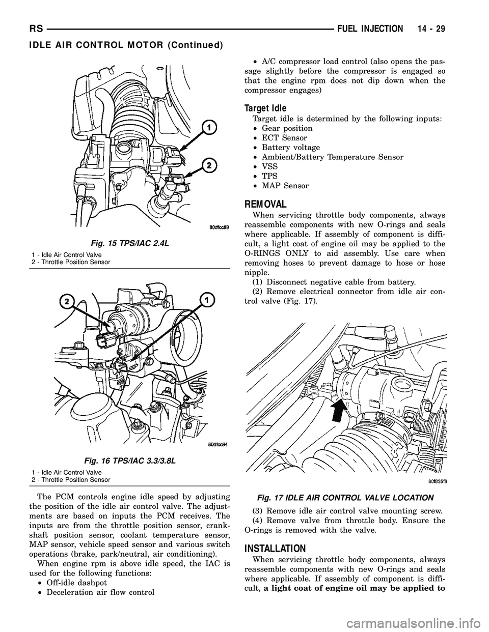
trol valve (Fig. 17).
(3) Remove idle air control valve mounting screw.
(4) Remove valve from throttle body. Ensure the
O-rings is removed with the valve.
INSTALLATION
When servicing throttle body components, always
reassemble components with new O-rings and seals
where applicable. If assembly of component is diffi-
cult,a light coat of engine oil may be applied to
Fig. 15 TPS/IAC 2.4L
1 - Idle Air Control Valve
2 - Throttle Position Sensor
Fig. 16 TPS/IAC 3.3/3.8L
1 - Idle Air Control Valve
2 - Throttle Position Sensor
Fig. 17 IDLE AIR CONTROL VALVE LOCATION
RSFUEL INJECTION14-29
IDLE AIR CONTROL MOTOR (Continued)
Page 1540 of 2585
The PCM adjusts injector pulse width based on pre-
programmed (fixed) values and inputs from other
sensors.
NGC Controller - Has a common ground for the
heater in the O2S. 12 volts is supplied to the heater
in the O2S by the NGC controller. Both the upstream
and downstream O2 sensors for NGC are pulse width
modulation (PWM).NOTE: When replacing an O2
Sensor, the PCM RAM memory must be cleared,
either by disconnecting the PCM C-1 connector or
momentarily disconnecting the Battery negative ter-
minal. The NGC learns the characteristics of each O2
heater element and these old values should be
cleared when installing a new O2 sensor. The cus-
tomer may experience driveability issues if this is not
performed.
UPSTREAM OXYGEN SENSOR
The input from the upstream heated oxygen sensor
tells the PCM the oxygen content of the exhaust gas.
Based on this input, the PCM fine tunes the air-fuel
ratio by adjusting injector pulse width.
The sensor input switches from 2.5 to 3.5 volt,
depending upon the oxygen content of the exhaust
gas in the exhaust manifold. When a large amount of
oxygen is present (caused by a lean air-fuel mixture),
the sensor produces voltage as low as 2.5 volt. When
there is a lesser amount of oxygen present (rich air-
fuel mixture) the sensor produces a voltage as high
as 3.5 volt. By monitoring the oxygen content and
converting it to electrical voltage, the sensor acts as
a rich-lean switch.
The heating element in the sensor provides heat to
the sensor ceramic element. Heating the sensor
allows the system to enter into closed loop operation
sooner. Also, it allows the system to remain in closed
loop operation during periods of extended idle.
In Closed Loop, the PCM adjusts injector pulse
width based on the upstream heated oxygen sensor
input along with other inputs. In Open Loop, the
PCM adjusts injector pulse width based on prepro-
grammed (fixed) values and inputs from other sen-
sors.
DOWNSTREAM OXYGEN SENSOR
The downstream heated oxygen sensor input is
used to detect catalytic convertor deterioration. As
the convertor deteriorates, the input from the down-
stream sensor begins to match the upstream sensor
input except for a slight time delay. By comparing
the downstream heated oxygen sensor input to the
input from the upstream sensor, the PCM calculates
catalytic convertor efficiency. Also used to establish
the upstream O2 goal voltage (switching point).
REMOVAL
REMOVAL - UPSTREAM 1/1 - 2.4L
(1) Disconnect the negative battery cable.
(2) Raise and support the vehicle.
(3) Disconnect the electrical connector (Fig. 23).
(4) Use a socket such as the Snap-OntYA8875 or
equivalent to remove the sensor
(5) When the sensor is removed, the threads must
be cleaned with an 18 mm X 1.5 + 6E tap. If using
the original sensor, coat the threads with Loctite
771±64 anti-seize compound or equivalent.
REMOVAL - UPSTREAM 1/1 - 3.3/3.8L
(1) Remove battery, refer to the Battery section for
more information.
(2) Remove the battery tray, refer to the Battery
section for more information.
(3) Disconnect the speed control vacuum harness
from servo.
(4) Disconnect the electrical connector from servo.
(5) Remove the speed control servo and bracket
and reposition.
(6) Use a socket such as the Snap-OntYA8875 or
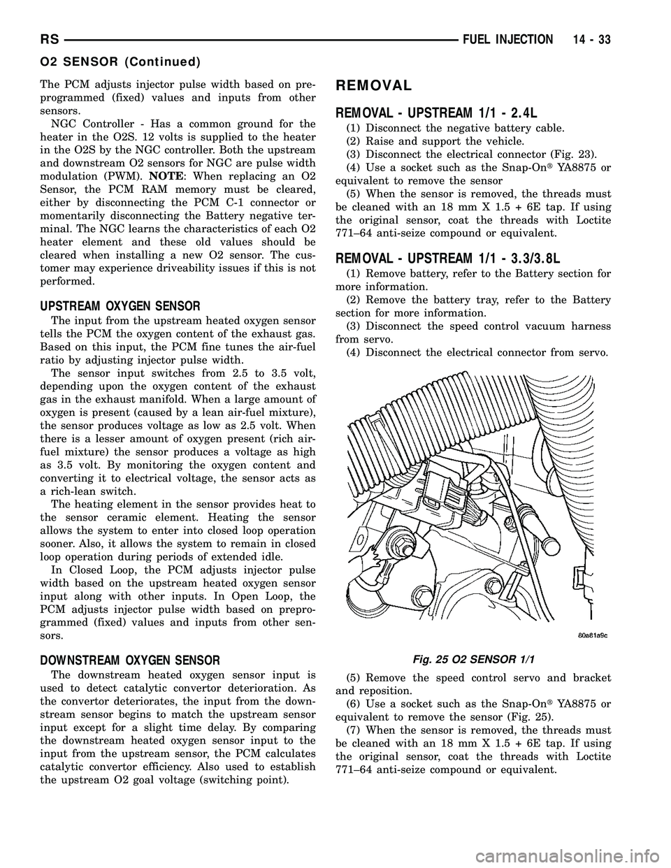
equivalent to remove the sensor (Fig. 25).
(7) When the sensor is removed, the threads must
be cleaned with an 18 mm X 1.5 + 6E tap. If using
the original sensor, coat the threads with Loctite
771±64 anti-seize compound or equivalent.
Fig. 25 O2 SENSOR 1/1
RSFUEL INJECTION14-33
O2 SENSOR (Continued)
Page 1550 of 2585

CONDITION POSSIBLE CAUSES CORRECTION
SQUEAK OR RUBBING
SOUND1. Steering column shroud rubbing. 1. Realign shrouds as necessary.
2. Steering column shaft rubbing. 2. Move or realign item rubbing shaft.
3. Clockspring noisy. 3. Remove clockspring. Reinstall wheel.
If noise is gone, replace clockspring.
4. Seal lubrication inadequate. 4. Lube seal (if external).
5. Steering gear internally noisy. 5. Replace steering gear (if no other
cause can be found).
SCRUBBING OR
KNOCKING NOISE.1. Incorrect tire or wheel size. 1. Replace incorrect size tire or wheel
with size used as original equipment.
2. Interference between steering
gear and other vehicle components.2. Check for bent or misaligned
components and correct as necessary.
3. Steering gear internal stops worn
excessively allowing tires to be
steered excessively far.3. Replace steering gear.
NOTE: * There is some noise in all power steering
systems. One of the most common is a hissing
sound evident when turning the steering wheel
when at a standstill or when parking and the steer-
ing wheel is at the end of its travel. Hiss is a very
high frequency noise similar to that experienced
while slowly closing a water tap. The noise is
present in every valve and results when high veloc-
ity fluid passes valve orifice edges. There is no
relationship between this noise and the perfor-
mance of the steering system.NOTE: ** A light clunk may be felt or heard during
steering wheel reversal while vehicle is stationary.
This results from internal steering gear rack move-
ment at the bushings and in no way affects the per-
formance of the steering system. This movement
may be felt in the steering components during
steering wheel reversal.
NOTE: *** Power steering pump growl/moan/groan
results from the development of high pressure fluid
flow. Normally this noise level should not be high
enough to be objectionable.
STEERING WHEEL FEEL
CONDITION POSSIBLE CAUSES CORRECTION
STEERING WHEEL/
COLUMN CLICKING,
CLUNKING OR RATTLING.1. Loose steering coupling pinch
bolt.1. Replace pinch bolt and torque to
specifications.
2. Steering column bearings. 2. Replace steering column.
3. Excessive intermediate shaft
coupling free-play.3. Replace intermediate shaft.
STEERING WHEEL HAS
FORE AND AFT
LOOSENESS.1. Steering wheel retaining nut not
properly tightened and torqued.1. Tighten the steering wheel retaining nut
to its specified torque.
2. Steering column lower bearing
spring retainer slipped on steering
column shaft.2. Replace steering column.
3. Loose steering column to
instrument panel fasteners.3. Tighten fasteners to specified torque.
RSSTEERING19-5
STEERING (Continued)
Page 1563 of 2585
(11) Disconnect the shifter/ignition interlock link
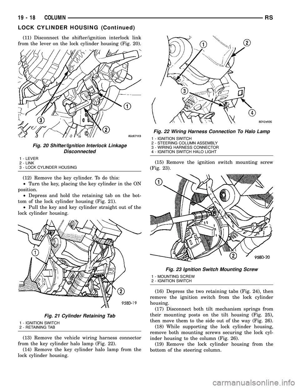
from the lever on the lock cylinder housing (Fig. 20).
(12) Remove the key cylinder. To do this:
²Turn the key, placing the key cylinder in the ON
position.
²Depress and hold the retaining tab on the bot-
tom of the lock cylinder housing (Fig. 21).
²Pull the key and key cylinder straight out of the
lock cylinder housing.
(13) Remove the vehicle wiring harness connector
from the key cylinder halo lamp (Fig. 22).
(14) Remove the key cylinder halo lamp from the
lock cylinder housing.(15) Remove the ignition switch mounting screw
(Fig. 23).
(16) Depress the two retaining tabs (Fig. 24), then
remove the ignition switch from the lock cylinder
housing.
(17) Disconnect both tilt mechanism springs from
their mounting posts on the tilt housing (Fig. 25),
then move them to the side out of the way (Fig. 26).
(18) While supporting the lock cylinder housing,
remove both mounting screws securing the lock cyl-
inder housing to the column (Fig. 26).
(19) Remove the lock cylinder housing from the
bottom of the steering column.
Fig. 20 Shifter/Ignition Interlock Linkage
Disconnected
1 - LEVER
2 - LINK
3 - LOCK CYLINDER HOUSING
Fig. 21 Cylinder Retaining Tab
1 - IGNITION SWITCH
2 - RETAINING TAB
Fig. 22 Wiring Harness Connection To Halo Lamp
1 - IGNITION SWITCH
2 - STEERING COLUMN ASSEMBLY
3 - WIRING HARNESS CONNECTOR
4 - IGNITION SWITCH HALO LIGHT
Fig. 23 Ignition Switch Mounting Screw
1 - MOUNTING SCREW
2 - IGNITION SWITCH
19 - 18 COLUMNRS
LOCK CYLINDER HOUSING (Continued)
Page 1582 of 2585
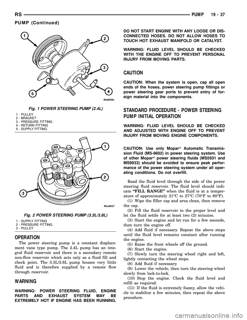
OPERATION
The power steering pump is a constant displace-
ment vane type pump. The 2.4L pump has an inte-
gral fluid reservoir and there is a secondary remote
non-flow reservoir which acts only as a fluid fill and
check point. The 3.3L/3.8L pump houses very little
fluid and is therefore supplied by a remote flow
through reservoir.
WARNING
WARNING: POWER STEERING FLUID, ENGINE
PARTS AND EXHAUST SYSTEM MAY BE
EXTREMELY HOT IF ENGINE HAS BEEN RUNNING.DO NOT START ENGINE WITH ANY LOOSE OR DIS-
CONNECTED HOSES. DO NOT ALLOW HOSES TO
TOUCH HOT EXHAUST MANIFOLD OR CATALYST.
WARNING: FLUID LEVEL SHOULD BE CHECKED
WITH THE ENGINE OFF TO PREVENT PERSONAL
INJURY FROM MOVING PARTS.
CAUTION
CAUTION: When the system is open, cap all open
ends of the hoses, power steering pump fittings or
power steering gear ports to prevent entry of for-
eign material into the components.
STANDARD PROCEDURE - POWER STEERING
PUMP INITIAL OPERATION
WARNING: FLUID LEVEL SHOULD BE CHECKED
AND ADJUSTED WITH ENGINE OFF TO PREVENT
INJURY FROM MOVING ENGINE COMPONENTS.
CAUTION: Use only MoparTAutomatic Transmis-
sion Fluid (MS-9602) in power steering system. Use
of other MoparTpower steering fluids (MS5931 and
MS9933) should be avoided to ensure peak perfor-
mance of the power steering system under all oper-
ating conditions. Do not overfill.
Read the fluid level through the side of the power
steering fluid reservoir. The fluid level should indi-
cateªFILL RANGEºwhen the fluid is at a temper-
ature of approximately 21ÉC to 27ÉC (70ÉF to 80ÉF).
(1) Wipe the filler cap and area clean, then remove
the cap.
(2) Fill the fluid reservoir to the proper level and
let the fluid settle for at least two (2) minutes.
(3) Start the engine and let run for a few seconds,
then turn the engine off.
(4) Add fluid if necessary. Repeat the above steps
until the fluid level remains constant after running
the engine.
(5) Raise the front wheels off the ground.
(6) Start the engine.
(7) Slowly turn the steering wheel right and left,
lightly contacting the wheel stops.
(8) Add fluid if necessary.
(9) Lower the vehicle, then turn the steering wheel
slowly from lock-to-lock.
(10) Stop the engine. Check the fluid level and
refill as required.
(11) If the fluid is extremely foamy, allow the vehi-
cle to stabilize a few minutes, then repeat the above
procedure.
Fig. 1 POWER STEERING PUMP (2.4L)
1 - PULLEY
2 - BRACKET
3 - PRESSURE FITTING
4 - RETURN FITTING
5 - SUPPLY FITTING
Fig. 2 POWER STEERING PUMP (3.3L/3.8L)
1 - SUPPLY FITTING
2 - PRESSURE FITTING
3 - PULLEY
RSPUMP19-37
PUMP (Continued)
Page 1600 of 2585
OPERATION
The Transfer Unit provides the power to the rear
wheels through a hypoid ring gear and pinion set.
DIAGNOSIS AND TESTING
SEAL IDENTIFICATION
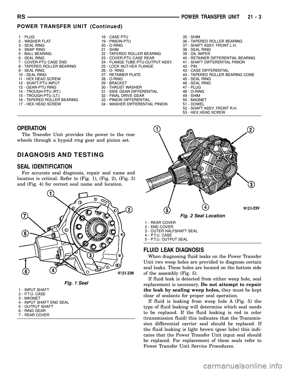
For accurate seal diagnosis, repair seal name and
location is critical. Refer to (Fig. 1), (Fig. 2), (Fig. 3)
and (Fig. 4) for correct seal name and location.
FLUID LEAK DIAGNOSIS
When diagnosing fluid leaks on the Power Transfer
Unit two weep holes are provided to diagnose certain
seal leaks. These holes are located on the bottom side
of the assembly (Fig. 5).
If fluid leak is detected from either weep hole, seal
replacement is necessary.Do not attempt to repair
the leak by sealing weep holes,they must be kept
clear of sealants for proper seal operation.
If fluid is leaking from weep hole A (Fig. 5) the
type of fluid leaking will determine which seal needs
to be replaced. If the fluid leaking is red in color
(transmission fluid) this indicates that the Transmis-
sion differential carrier seal should be replaced. If
the fluid leaking is light brown (gear lube) this indi-
cates that the Power Transfer Unit input seal should
be replaced. For replacement of these seals refer to
Power Transfer Unit Service Procedures.
1 - PLUG 18 - CASE-PTU 35 - SHIM
2 - WASHER FLAT 19 - PINION-PTU 36 - TAPERED ROLLER BEARING
3 - SEAL RING 20 - O-RING 37 - SHAFT ASSY. FRONT L.H.
4 - SNAP RING 21 - SHIM 38 - SEAL RING
5 - BALL BEARING 22 - TAPERED ROLLER BEARING 39 - OIL WIPER
6 - SEAL RING 23 - COVER-PTU CASE REAR 40 - RETAINER DIFFERENTIAL BEARING
7 - COVER-PTU CASE END 24 - FLANGE TUBE-PTU-OUTPUT ASSY. 41 - SHAFT DIFFERENTIAL PINION
8 - TAPERED ROLLER BEARING 25 - LOCK NUT-HEX FLANGE 42 - PIN
9 - SEAL RING 26 - O- RING 43 - CASE DIFFERENTIAL
10 - SEAL RING 27 - RETAINER PLATE 44 - TAPERED ROLLER BEARING CONE
11 - HEX HEAD SCREW 28 - O-RING 45 - SEAL RING
12 - SHAFT-PTU INPUT 29 - BRACKET 46 - SEAL RING
13 - GEAR-PTU RING 30 - THRUST WASHER 47 - PLUG
14 - TROUGH-PTU (RT.) 31 - SIDE GEAR-DIFFERENTIAL 48 - O-RING
15 - TROUGH-PTU (LT.) 32 - FINAL DRIVE GEAR 49 - SHIM
16 - TAPERED ROLLER BEARING 33 - PINION DIFFERENTIAL 50 - MAGNET
17 - HEX HEAD SCREW 34 - WASHER DIFFERENTIAL PINION 51 - DOWEL
52 - SHAFT ASSY. FRONT R.H.
53 - HEX HEAD SCREW
Fig. 1 Seal
1 - INPUT SHAFT
2 - P.T.U. CASE
3 - MAGNET
4 - INPUT SHAFT END SEAL
5 - OUTPUT SHAFT
6 - RING GEAR
7 - REAR COVER
Fig. 2 Seal Location
1 - REAR COVER
2 - END COVER
3 - OUTER HALFSHAFT SEAL
4 - P.T.U. CASE
5 - P.T.U. OUTPUT SEAL
RSPOWER TRANSFER UNIT21-3
POWER TRANSFER UNIT (Continued)
Page 1601 of 2585
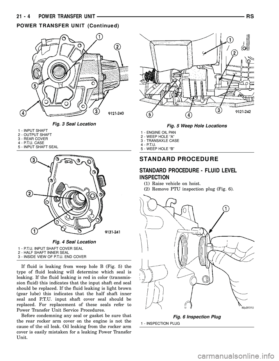
If fluid is leaking from weep hole B (Fig. 5) the
type of fluid leaking will determine which seal is
leaking. If the fluid leaking is red in color (transmis-
sion fluid) this indicates that the input shaft end seal
should be replaced. If the fluid leaking is light brown
(gear lube) this indicates that the half shaft inner
seal and P.T.U. input shaft cover seal should be
replaced. For replacement of these seals refer to
Power Transfer Unit Service Procedures.
Before condemning any seal or gasket be sure that
the rear rocker arm cover on the engine is not the
cause of the oil leak. Oil leaking from the rocker arm
cover is easily mistaken for a leaking Power Transfer
Unit.
STANDARD PROCEDURE
STANDARD PROCEDURE - FLUID LEVEL
INSPECTION
(1) Raise vehicle on hoist.
(2) Remove PTU inspection plug (Fig. 6).
Fig. 3 Seal Location
1 - INPUT SHAFT
2 - OUTPUT SHAFT
3 - REAR COVER
4 - P.T.U. CASE
5 - INPUT SHAFT SEAL
Fig. 4 Seal Location
1 - P.T.U. INPUT SHAFT COVER SEAL
2 - HALF SHAFT INNER SEAL
3 - INSIDE VIEW OF P.T.U. END COVER
Fig. 5 Weep Hole Locations
1 - ENGINE OIL PAN
2 - WEEP HOLE ªAº
3 - TRANSAXLE CASE
4 - P.T.U.
5 - WEEP HOLE ªBº
Fig. 6 Inspection Plug
1 - INSPECTION PLUG
21 - 4 POWER TRANSFER UNITRS
POWER TRANSFER UNIT (Continued)