2004 CHRYSLER VOYAGER light
[x] Cancel search: lightPage 1307 of 2585
Calibrate the tester according to the manufactur-
er's instructions. The shop air source for testing
should maintain 483 kPa (70 psi) minimum, 1,379
kPa (200 psi) maximum, with 552 kPa (80 psi) rec-
ommended.
Perform the test procedures on each cylinder
according to the tester manufacturer's instructions.
While testing, listen for pressurized air escaping
through the throttle body, tailpipe and oil filler cap
opening. Check for bubbles in the coolant.
All gauge pressure indications should be equal,
with no more than 25% leakage per cylinder.
FOR EXAMPLE:At 552 kPa (80 psi) input pres-
sure, a minimum of 414 kPa (60 psi) should be main-
tained in the cylinder.
STANDARD PROCEDURE
STANDARD PROCEDURE - ENGINE CORE AND
OIL GALLERY PLUGS
Using a blunt tool such as a drift and a hammer,
strike the bottom edge of the cup plug. With the cup
plug rotated, grasp firmly with pliers or other suit-
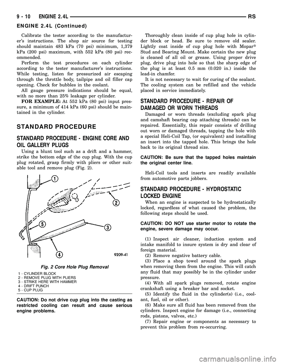
able tool and remove plug (Fig. 2).
CAUTION: Do not drive cup plug into the casting as
restricted cooling can result and cause serious
engine problems.Thoroughly clean inside of cup plug hole in cylin-
der block or head. Be sure to remove old sealer.
Lightly coat inside of cup plug hole with Mopart
Stud and Bearing Mount. Make certain the new plug
is cleaned of all oil or grease. Using proper drive
plug, drive plug into hole so that the sharp edge of
the plug is at least 0.5 mm (0.020 in.) inside the
lead-in chamfer.
It is not necessary to wait for curing of the sealant.
The cooling system can be refilled and the vehicle
placed in service immediately.
STANDARD PROCEDURE - REPAIR OF
DAMAGED OR WORN THREADS
Damaged or worn threads (excluding spark plug
and camshaft bearing cap attaching threads) can be
repaired. Essentially, this repair consists of drilling
out worn or damaged threads, tapping the hole with
a special Heli-Coil Tap, (or equivalent) and installing
an insert into the tapped hole. This brings the hole
back to its original thread size.
CAUTION: Be sure that the tapped holes maintain
the original center line.
Heli-Coil tools and inserts are readily available
from automotive parts jobbers.
STANDARD PROCEDURE - HYDROSTATIC
LOCKED ENGINE
When an engine is suspected to be hydrostatically
locked, regardless of what caused the problem, the
following steps should be used.
CAUTION: DO NOT use starter motor to rotate the
engine, severe damage may occur.
(1) Inspect air cleaner, induction system and
intake manifold to insure system is dry and clear of
foreign material.
(2) Remove negative battery cable.
(3) Place a shop towel around the spark plugs
when removing them from the engine. This will catch
any fluid that may possibly be in the cylinder under
pressure.
(4) With all spark plugs removed, rotate engine
crankshaft using a breaker bar and socket.
(5) Identify the fluid in the cylinder(s) (i.e., cool-
ant, fuel, oil or other).
(6) Make sure all fluid has been removed from the
cylinders. Inspect engine for damage (i.e., connecting
rods, pistons, valves, etc.)
(7) Repair engine or components as necessary to
prevent this problem from re-occurring.
Fig. 2 Core Hole Plug Removal
1 - CYLINDER BLOCK
2 - REMOVE PLUG WITH PLIERS
3 - STRIKE HERE WITH HAMMER
4 - DRIFT PUNCH
5 - CUP PLUG
9 - 10 ENGINE 2.4LRS
ENGINE 2.4L (Continued)
Page 1332 of 2585
INSPECTION
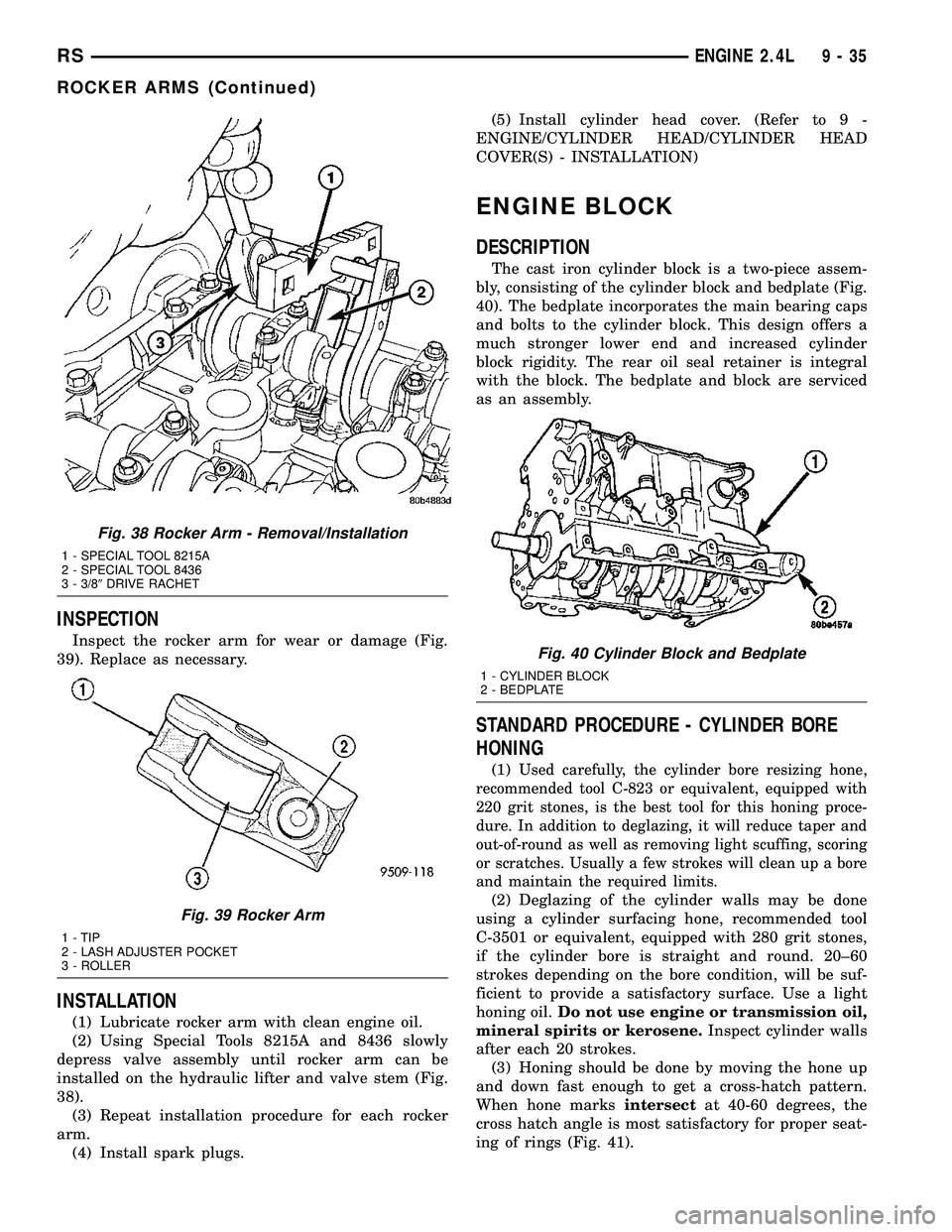
Inspect the rocker arm for wear or damage (Fig.
39). Replace as necessary.
INSTALLATION
(1) Lubricate rocker arm with clean engine oil.
(2) Using Special Tools 8215A and 8436 slowly
depress valve assembly until rocker arm can be
installed on the hydraulic lifter and valve stem (Fig.
38).
(3) Repeat installation procedure for each rocker
arm.
(4) Install spark plugs.(5) Install cylinder head cover. (Refer to 9 -
ENGINE/CYLINDER HEAD/CYLINDER HEAD
COVER(S) - INSTALLATION)
ENGINE BLOCK
DESCRIPTION
The cast iron cylinder block is a two-piece assem-
bly, consisting of the cylinder block and bedplate (Fig.
40). The bedplate incorporates the main bearing caps
and bolts to the cylinder block. This design offers a
much stronger lower end and increased cylinder
block rigidity. The rear oil seal retainer is integral
with the block. The bedplate and block are serviced
as an assembly.
STANDARD PROCEDURE - CYLINDER BORE
HONING
(1)Used carefully, the cylinder bore resizing hone,
recommended tool C-823 or equivalent, equipped with
220 grit stones, is the best tool for this honing proce-
dure. In addition to deglazing, it will reduce taper and
out-of-round as well as removing light scuffing, scoring
or scratches. Usually a few strokes will clean up a bore
and maintain the required limits.
(2) Deglazing of the cylinder walls may be done
using a cylinder surfacing hone, recommended tool
C-3501 or equivalent, equipped with 280 grit stones,
if the cylinder bore is straight and round. 20±60
strokes depending on the bore condition, will be suf-
ficient to provide a satisfactory surface. Use a light
honing oil.Do not use engine or transmission oil,
mineral spirits or kerosene.Inspect cylinder walls
after each 20 strokes.
(3) Honing should be done by moving the hone up
and down fast enough to get a cross-hatch pattern.
When hone marksintersectat 40-60 degrees, the
cross hatch angle is most satisfactory for proper seat-
ing of rings (Fig. 41).
Fig. 38 Rocker Arm - Removal/Installation
1 - SPECIAL TOOL 8215A
2 - SPECIAL TOOL 8436
3 - 3/89DRIVE RACHET
Fig. 39 Rocker Arm
1 - TIP
2 - LASH ADJUSTER POCKET
3 - ROLLER
Fig. 40 Cylinder Block and Bedplate
1 - CYLINDER BLOCK
2 - BEDPLATE
RSENGINE 2.4L9-35
ROCKER ARMS (Continued)
Page 1370 of 2585
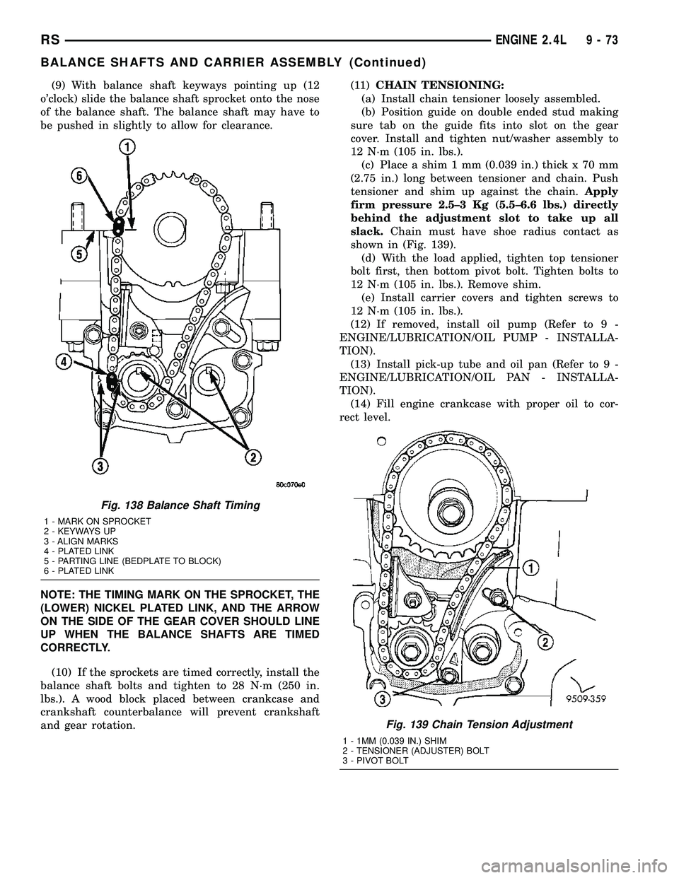
(9) With balance shaft keyways pointing up (12
o'clock) slide the balance shaft sprocket onto the nose
of the balance shaft. The balance shaft may have to
be pushed in slightly to allow for clearance.
NOTE: THE TIMING MARK ON THE SPROCKET, THE
(LOWER) NICKEL PLATED LINK, AND THE ARROW
ON THE SIDE OF THE GEAR COVER SHOULD LINE
UP WHEN THE BALANCE SHAFTS ARE TIMED
CORRECTLY.
(10) If the sprockets are timed correctly, install the
balance shaft bolts and tighten to 28 N´m (250 in.
lbs.). A wood block placed between crankcase and
crankshaft counterbalance will prevent crankshaft
and gear rotation.(11)CHAIN TENSIONING:
(a) Install chain tensioner loosely assembled.
(b) Position guide on double ended stud making
sure tab on the guide fits into slot on the gear
cover. Install and tighten nut/washer assembly to
12 N´m (105 in. lbs.).
(c) Place a shim 1 mm (0.039 in.) thick x 70 mm
(2.75 in.) long between tensioner and chain. Push
tensioner and shim up against the chain.Apply
firm pressure 2.5±3 Kg (5.5±6.6 lbs.) directly
behind the adjustment slot to take up all
slack.Chain must have shoe radius contact as
shown in (Fig. 139).
(d) With the load applied, tighten top tensioner
bolt first, then bottom pivot bolt. Tighten bolts to
12 N´m (105 in. lbs.). Remove shim.
(e) Install carrier covers and tighten screws to
12 N´m (105 in. lbs.).
(12) If removed, install oil pump (Refer to 9 -
ENGINE/LUBRICATION/OIL PUMP - INSTALLA-
TION).
(13) Install pick-up tube and oil pan (Refer to 9 -
ENGINE/LUBRICATION/OIL PAN - INSTALLA-
TION).
(14) Fill engine crankcase with proper oil to cor-
rect level.
Fig. 138 Balance Shaft Timing
1 - MARK ON SPROCKET
2 - KEYWAYS UP
3 - ALIGN MARKS
4 - PLATED LINK
5 - PARTING LINE (BEDPLATE TO BLOCK)
6 - PLATED LINK
Fig. 139 Chain Tension Adjustment
1 - 1MM (0.039 IN.) SHIM
2 - TENSIONER (ADJUSTER) BOLT
3 - PIVOT BOLT
RSENGINE 2.4L9-73
BALANCE SHAFTS AND CARRIER ASSEMBLY (Continued)
Page 1375 of 2585
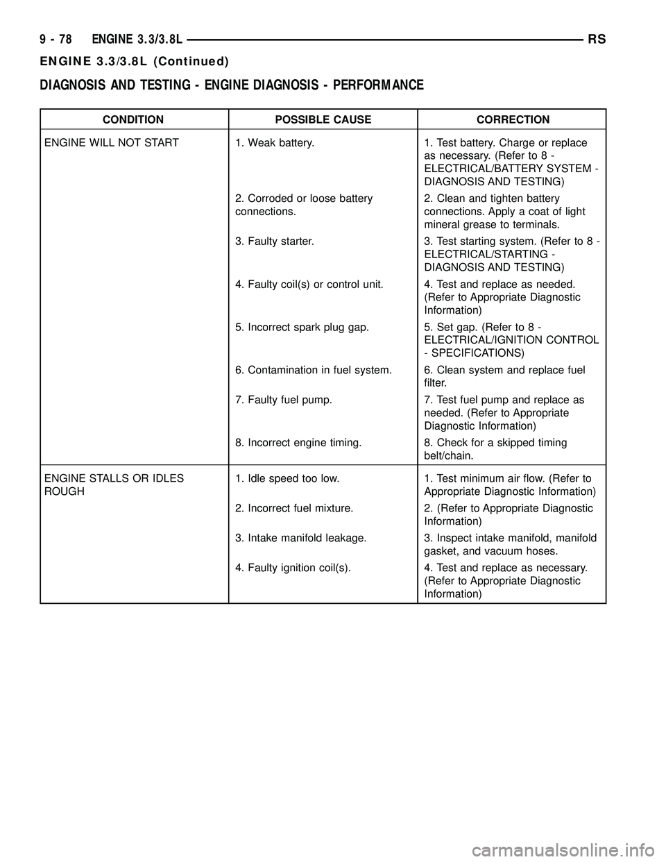
DIAGNOSIS AND TESTING - ENGINE DIAGNOSIS - PERFORMANCE
CONDITION POSSIBLE CAUSE CORRECTION
ENGINE WILL NOT START 1. Weak battery. 1. Test battery. Charge or replace
as necessary. (Refer to 8 -
ELECTRICAL/BATTERY SYSTEM -
DIAGNOSIS AND TESTING)
2. Corroded or loose battery
connections.2. Clean and tighten battery
connections. Apply a coat of light
mineral grease to terminals.
3. Faulty starter. 3. Test starting system. (Refer to 8 -
ELECTRICAL/STARTING -
DIAGNOSIS AND TESTING)
4. Faulty coil(s) or control unit. 4. Test and replace as needed.
(Refer to Appropriate Diagnostic
Information)
5. Incorrect spark plug gap. 5. Set gap. (Refer to 8 -
ELECTRICAL/IGNITION CONTROL
- SPECIFICATIONS)
6. Contamination in fuel system. 6. Clean system and replace fuel
filter.
7. Faulty fuel pump. 7. Test fuel pump and replace as
needed. (Refer to Appropriate
Diagnostic Information)
8. Incorrect engine timing. 8. Check for a skipped timing
belt/chain.
ENGINE STALLS OR IDLES
ROUGH1. Idle speed too low. 1. Test minimum air flow. (Refer to
Appropriate Diagnostic Information)
2. Incorrect fuel mixture. 2. (Refer to Appropriate Diagnostic
Information)
3. Intake manifold leakage. 3. Inspect intake manifold, manifold
gasket, and vacuum hoses.
4. Faulty ignition coil(s). 4. Test and replace as necessary.
(Refer to Appropriate Diagnostic
Information)
9 - 78 ENGINE 3.3/3.8LRS
ENGINE 3.3/3.8L (Continued)
Page 1379 of 2585
CONDITION POSSIBLE CAUSES CORRECTION
OIL CONSUMPTION OR SPARK
PLUGS FOULED1. PCV system malfunction. 1. Check system and repair as
necessary. (Refer to 25 -
EMISSIONS CONTROL/
EVAPORATIVE EMISSIONS/PCV
VALVE - DIAGNOSIS AND
TESTING)
2. Worn, scuffed or broken rings. 2. Hone cylinder bores. Install new
rings.
3. Carbon in oil ring slots. 3. Install new rings.
4. Rings fitted too tightly in grooves. 4. Remove rings and check
grooves. If groove is not proper
width, replace piston.
5. Worn valve guide(s). 5. Replace cylinder head assembly.
6. Valve stem seal(s) worn or
damaged.6. Replace seal(s).
DIAGNOSIS AND TESTING - ENGINE OIL LEAK
INSPECTION
Begin with a thorough visual inspection of the
engine, particularly at the area of the suspected leak.
If an oil leak source is not readily identifiable, the
following steps should be followed:
(1) Do not clean or degrease the engine at this
time because some solvents may cause rubber to
swell, temporarily stopping the leak.
(2) Add an oil soluble dye (use as recommended by
manufacturer). Start the engine and let idle for
approximately 15 minutes. Check the oil dipstick to
make sure the dye is thoroughly mixed as indicated
with a bright yellow color under a black light.
(3) Using a black light, inspect the entire engine
for fluorescent dye, particularly at the suspected area
of oil leak. If the oil leak is found and identified,
repair as necessary.
(4) If dye is not observed, drive the vehicle at var-
ious speeds for approximately 24 km (15 miles), and
repeat inspection.
(5)If the oil leak source is not positively
identified at this time, proceed with the air leak
detection test method as follows:
²Disconnect the fresh air hose (make-up air) at
the cylinder head cover and plug or cap the nipple on
the cover.
²Remove the PCV valve hose from the cylinder
head cover. Cap or plug the PCV valve nipple on the
cover.
²Attach an air hose with pressure gauge and reg-
ulator to the dipstick tube.
CAUTION: Do not subject the engine assembly to
more than 20.6 kpa (3 PSI) of test pressure.²Gradually apply air pressure from 1 psi to 2.5
psi maximum while applying soapy water at the sus-
pected source. Adjust the regulator to the suitable
test pressure that provides the best bubbles which
will pinpoint the leak source. If the oil leak is
detected and identified, repair per service manual
procedures.
²If the leakage occurs at the crankshaft rear oil
seal area, refer to the section, Inspection for Rear
Seal Area Leak.
(6) If no leaks are detected, turn off the air supply.
Remove the air hose, all plugs, and caps. Install the
PCV valve and fresh air hose (make-up air). Proceed
to next step.
(7) Clean the oil off the suspect oil leak area using
a suitable solvent. Drive the vehicle at various
speeds approximately 24 km (15 miles). Inspect the
engine for signs of an oil leak by using a black light.
NOTE: If oil leakage is observed at the dipstick tube
to block location; remove the tube, clean and reseal
using MoparTStud & Bearing Mount (press fit tube
applications only), and for O-ring style tubes,
remove tube and replace the O-ring seal.
INSPECTION FOR REAR SEAL AREA LEAKS
Since it is sometimes difficult to determine the
source of an oil leak in the rear seal area of the
engine, a more involved inspection is necessary. The
following steps should be followed to help pinpoint
the source of the leak.
If the leakage occurs at the crankshaft rear oil seal
area:
(1) Disconnect the battery.
(2) Raise the vehicle.
9 - 82 ENGINE 3.3/3.8LRS
ENGINE 3.3/3.8L (Continued)
Page 1380 of 2585
(3) Remove torque converter or clutch housing
cover and inspect rear of block for evidence of oil.
Use a black light to check for the oil leak. If a leak is
present in this area, remove transmission for further
inspection.
(a) Circular spray pattern generally indicates
seal leakage or crankshaft damage.
(b) Where leakage tends to run straight down,
possible causes are a porous block, oil gallery cup
plug, bedplate to cylinder block mating surfaces
and seal bore. See proper repair procedures for
these items.
(4) If no leaks are detected, pressurize the crank-
case as previously described.
CAUTION: Do not exceed 20.6 kPa (3 psi).
(5) If the leak is not detected, very slowly turn the
crankshaft and watch for leakage. If a leak is
detected between the crankshaft and seal while
slowly turning the crankshaft, it is possible the
crankshaft seal surface is damaged. The seal area on
the crankshaft could have minor nicks or scratches
that can be polished out with emery cloth.
CAUTION: Use extreme caution when crankshaft
polishing is necessary to remove minor nicks and
scratches. The crankshaft seal flange is especially
machined to complement the function of the rear oil
seal.
(6) For bubbles that remain steady with shaft
rotation, no further inspection can be done until dis-
assembled.
(7) After the oil leak root cause and appropriate
corrective action have been identified, replace compo-
nent(s) as necessary.
DIAGNOSIS AND TESTING - CYLINDER
COMPRESSION PRESSURE TEST
The results of a cylinder compression pressure test
can be utilized to diagnose several engine malfunc-
tions.
Ensure the battery is completely charged and the
engine starter motor is in good operating condition.
Otherwise the indicated compression pressures may
not be valid for diagnosis purposes.
(1) Check engine oil level and add oil if necessary.
(2) Drive the vehicle until engine reaches normal
operating temperature. Select a route free from traf-
fic and other forms of congestion, observe all traffic
laws, and accelerate through the gears several times
briskly.
(3) Remove all spark plugs from engine. As spark
plugs are being removed, check electrodes for abnor-
mal firing indicators fouled, hot, oily, etc. Record cyl-
inder number of spark plug for future reference.(4) Remove the Auto Shutdown (ASD) relay from
the PDC.
(5) Be sure throttle blade is fully open during the
compression check.
(6) Insert compression gauge adaptor Special Tool
8116 or the equivalent, into the #1 spark plug hole in
cylinder head. Connect the 0±500 psi (Blue) pressure
transducer (Special Tool CH7059) with cable adap-
tors to the DRBIIIt. For Special Tool identification,
(Refer to 9 - ENGINE - SPECIAL TOOLS).
(7) Crank engine until maximum pressure is
reached on gauge. Record this pressure as #1 cylin-
der pressure.
(8) Repeat the previous step for all remaining cyl-
inders.
(9) Compression should not be less than 689 kPa
(100 psi) and not vary more than 25 percent from cyl-
inder to cylinder.
(10) If one or more cylinders have abnormally low
compression pressures, repeat the compression test.
(11) If the same cylinder or cylinders repeat an
abnormally low reading on the second compression
test, it could indicate the existence of a problem in
the cylinder in question.The recommended com-
pression pressures are to be used only as a
guide to diagnosing engine problems. An engine
should not be disassembled to determine the
cause of low compression unless some malfunc-
tion is present.
DIAGNOSIS AND TESTING - CYLINDER
COMBUSTION PRESSURE LEAKAGE TEST
The combustion pressure leakage test provides an
accurate means for determining engine condition.
Combustion pressure leakage testing will detect:
²Exhaust and intake valve leaks (improper seat-
ing).
²Leaks between adjacent cylinders or into water
jacket.
²Any causes for combustion/compression pressure
loss.
WARNING: DO NOT REMOVE THE PRESSURE CAP
WITH THE SYSTEM HOT AND UNDER PRESSURE
BECAUSE SERIOUS BURNS FROM COOLANT CAN
OCCUR.
Check the coolant level and fill as required. DO
NOT install the pressure cap.
Start and operate the engine until it attains nor-
mal operating temperature, then turn the engine
OFF.
Clean spark plug recesses with compressed air.
Remove the spark plugs.
Remove the oil filler cap.
Remove the air cleaner.
RSENGINE 3.3/3.8L9-83
ENGINE 3.3/3.8L (Continued)
Page 1383 of 2585
(1) Inspect air cleaner, induction system and
intake manifold to insure system is dry and clear of
foreign material.
(2) Remove negative battery cable.
(3) Place a shop towel around the spark plugs
when removing them from the engine. This will catch
any fluid that may possibly be in the cylinder under
pressure.
(4) With all spark plugs removed, rotate engine
crankshaft using a breaker bar and socket.
(5) Identify the fluid in the cylinder(s) (i.e., cool-
ant, fuel, oil or other).
(6) Make sure all fluid has been removed from the
cylinders. Inspect engine for damage (i.e., connecting
rods, pistons, valves, etc.)
(7) Repair engine or components as necessary to
prevent this problem from re-occurring.
CAUTION: Squirt approximately one teaspoon of oil
into the cylinders, rotate engine to lubricate the cyl-
inder walls to prevent damage on restart.
(8) Install new spark plugs.
(9) Drain engine oil and remove oil filter.
(10) Install a new oil filter.
(11) Fill engine with specified amount of approved
oil.
(12) Connect negative battery cable.
(13) Start engine and check for any leaks.
STANDARD PROCEDURE - REPAIR OF
DAMAGED OR WORN THREADS
Damaged or worn threads (excluding spark plug
and camshaft bearing cap attaching threads) can be
repaired. Essentially, this repair consists of drilling
out worn or damaged threads, tapping the hole with
a special Heli-Coil Tap, (or equivalent) and installing
an insert into the tapped hole. This brings the hole
back to its original thread size.
CAUTION: Be sure that the tapped holes maintain
the original center line.
Heli-Coil tools and inserts are readily available
from automotive parts jobbers.
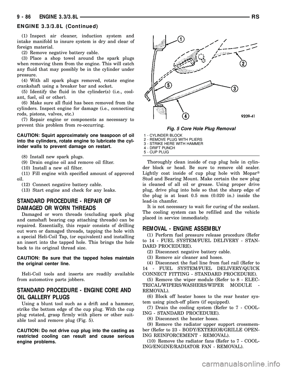
STANDARD PROCEDURE - ENGINE CORE AND
OIL GALLERY PLUGS
Using a blunt tool such as a drift and a hammer,
strike the bottom edge of the cup plug. With the cup
plug rotated, grasp firmly with pliers or other suit-
able tool and remove plug (Fig. 5).
CAUTION: Do not drive cup plug into the casting as
restricted cooling can result and cause serious
engine problems.Thoroughly clean inside of cup plug hole in cylin-
der block or head. Be sure to remove old sealer.
Lightly coat inside of cup plug hole with Mopart
Stud and Bearing Mount. Make certain the new plug
is cleaned of all oil or grease. Using proper drive
plug, drive plug into hole so that the sharp edge of
the plug is at least 0.5 mm (0.020 in.) inside the
lead-in chamfer.
It is not necessary to wait for curing of the sealant.
The cooling system can be refilled and the vehicle
placed in service immediately.
REMOVAL - ENGINE ASSEMBLY
(1) Perform fuel pressure release procedure (Refer
to 14 - FUEL SYSTEM/FUEL DELIVERY - STAN-
DARD PROCEDURE).
(2) Disconnect negative battery cable.
(3) Remove air cleaner and hoses.
(4) Disconnect the fuel line from fuel rail (Refer to
14 - FUEL SYSTEM/FUEL DELIVERY/QUICK
CONNECT FITTING - STANDARD PROCEDURE).
(5) Remove the wiper module (Refer to 8 - ELEC-
TRICAL/WIPERS/WASHERS/WIPER MODULE -
REMOVAL).
(6) Block off heater hoses to the rear heater sys-
tem using pinch-off pliers (if equipped).
(7) Drain the cooling system (Refer to 7 - COOL-
ING - STANDARD PROCEDURE).
(8) Disconnect the heater hoses.
(9) Remove the radiator upper support crossmem-
ber (Refer to 23 - BODY/EXTERIOR/GRILLE OPEN-
ING REINFORCEMENT - REMOVAL).
(10) Remove the radiator fans (Refer to 7 - COOL-
ING/ENGINE/RADIATOR FAN - REMOVAL).
Fig. 5 Core Hole Plug Removal
1 - CYLINDER BLOCK
2 - REMOVE PLUG WITH PLIERS
3 - STRIKE HERE WITH HAMMER
4 - DRIFT PUNCH
5 - CUP PLUG
9 - 86 ENGINE 3.3/3.8LRS
ENGINE 3.3/3.8L (Continued)
Page 1401 of 2585
(2) Assemble gasket to cylinder cover by inserting
the fasteners through each bolt hole on cover and
gasket (Fig. 25).
(3) Install the cylinder head cover and bolts (Fig.
26).
(4) Tighten cylinder head cover bolts to 12 N´m
(105 in. lbs.) (Fig. 26).
(5) Connect crankcase vent hose.
(6) Connect spark plug wires to spark plugs.
INTAKE/EXHAUST VALVES &
SEATS
DESCRIPTION
The valves have chrome plated valve stems with
four-bead lock grooves. The valve stem seals are
made of Viton rubber.
OPERATION
The two valves per cylinder are opened using
hydraulic lifters, push rods, and rocker arms.
STANDARD PROCEDURE - REFACING VALVES
AND VALVE SEATS
The intake and exhaust valves and seats are
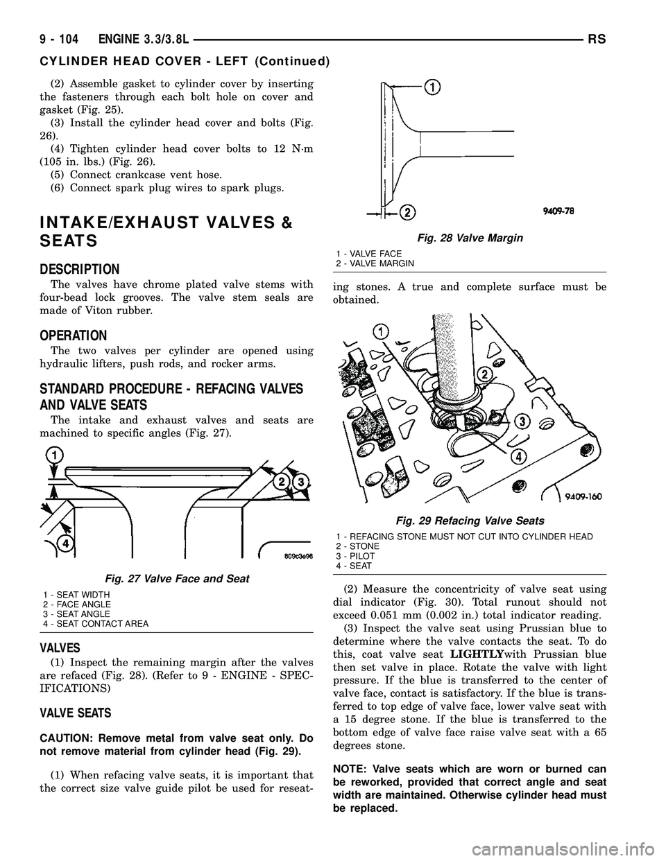
machined to specific angles (Fig. 27).
VALVES
(1) Inspect the remaining margin after the valves
are refaced (Fig. 28). (Refer to 9 - ENGINE - SPEC-
IFICATIONS)
VALVE SEATS
CAUTION: Remove metal from valve seat only. Do
not remove material from cylinder head (Fig. 29).
(1) When refacing valve seats, it is important that
the correct size valve guide pilot be used for reseat-ing stones. A true and complete surface must be
obtained.
(2) Measure the concentricity of valve seat using
dial indicator (Fig. 30). Total runout should not
exceed 0.051 mm (0.002 in.) total indicator reading.
(3) Inspect the valve seat using Prussian blue to
determine where the valve contacts the seat. To do
this, coat valve seatLIGHTLYwith Prussian blue
then set valve in place. Rotate the valve with light
pressure. If the blue is transferred to the center of
valve face, contact is satisfactory. If the blue is trans-
ferred to top edge of valve face, lower valve seat with
a 15 degree stone. If the blue is transferred to the
bottom edge of valve face raise valve seat with a 65
degrees stone.
NOTE: Valve seats which are worn or burned can
be reworked, provided that correct angle and seat
width are maintained. Otherwise cylinder head must
be replaced.
Fig. 27 Valve Face and Seat
1 - SEAT WIDTH
2 - FACE ANGLE
3 - SEAT ANGLE
4 - SEAT CONTACT AREA
Fig. 28 Valve Margin
1 - VALVE FACE
2 - VALVE MARGIN
Fig. 29 Refacing Valve Seats
1 - REFACING STONE MUST NOT CUT INTO CYLINDER HEAD
2-STONE
3 - PILOT
4 - SEAT
9 - 104 ENGINE 3.3/3.8LRS
CYLINDER HEAD COVER - LEFT (Continued)