2004 CHRYSLER VOYAGER light
[x] Cancel search: lightPage 1406 of 2585
ROCKER ARMS
DESCRIPTION
DESCRIPTION - ROCKER ARMS
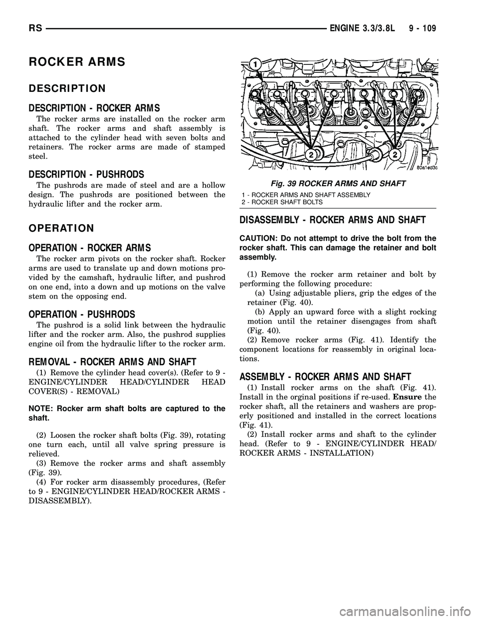
The rocker arms are installed on the rocker arm
shaft. The rocker arms and shaft assembly is
attached to the cylinder head with seven bolts and
retainers. The rocker arms are made of stamped
steel.
DESCRIPTION - PUSHRODS
The pushrods are made of steel and are a hollow
design. The pushrods are positioned between the
hydraulic lifter and the rocker arm.
OPERATION
OPERATION - ROCKER ARMS
The rocker arm pivots on the rocker shaft. Rocker
arms are used to translate up and down motions pro-
vided by the camshaft, hydraulic lifter, and pushrod
on one end, into a down and up motions on the valve
stem on the opposing end.
OPERATION - PUSHRODS
The pushrod is a solid link between the hydraulic
lifter and the rocker arm. Also, the pushrod supplies
engine oil from the hydraulic lifter to the rocker arm.
REMOVAL - ROCKER ARMS AND SHAFT
(1) Remove the cylinder head cover(s). (Refer to 9 -
ENGINE/CYLINDER HEAD/CYLINDER HEAD
COVER(S) - REMOVAL)
NOTE: Rocker arm shaft bolts are captured to the
shaft.
(2) Loosen the rocker shaft bolts (Fig. 39), rotating
one turn each, until all valve spring pressure is
relieved.
(3) Remove the rocker arms and shaft assembly
(Fig. 39).
(4) For rocker arm disassembly procedures, (Refer
to 9 - ENGINE/CYLINDER HEAD/ROCKER ARMS -
DISASSEMBLY).
DISASSEMBLY - ROCKER ARMS AND SHAFT
CAUTION: Do not attempt to drive the bolt from the
rocker shaft. This can damage the retainer and bolt
assembly.
(1) Remove the rocker arm retainer and bolt by
performing the following procedure:
(a) Using adjustable pliers, grip the edges of the
retainer (Fig. 40).
(b) Apply an upward force with a slight rocking
motion until the retainer disengages from shaft
(Fig. 40).
(2) Remove rocker arms (Fig. 41). Identify the
component locations for reassembly in original loca-
tions.
ASSEMBLY - ROCKER ARMS AND SHAFT
(1) Install rocker arms on the shaft (Fig. 41).
Install in the orginal positions if re-used.Ensurethe
rocker shaft, all the retainers and washers are prop-
erly positioned and installed in the correct locations
(Fig. 41).
(2) Install rocker arms and shaft to the cylinder
head. (Refer to 9 - ENGINE/CYLINDER HEAD/
ROCKER ARMS - INSTALLATION)
Fig. 39 ROCKER ARMS AND SHAFT
1 - ROCKER ARMS AND SHAFT ASSEMBLY
2 - ROCKER SHAFT BOLTS
RSENGINE 3.3/3.8L9 - 109
Page 1409 of 2585
REMOVAL
(1) Remove the valve springs. (Refer to 9 -
ENGINE/CYLINDER HEAD/VALVE SPRINGS -
REMOVAL)
(2) Remove the valve stem seal (Fig. 43).
INSTALLATION
(1) Install the valve stem seal squarely over the
valve guide, using the valve stem as a guide (Fig.
43). Do not force the seal against top of the valve
guide.
(2) Install the valve spring. (Refer to 9 - ENGINE/
CYLINDER HEAD/VALVE SPRINGS - INSTALLA-
TION)
ENGINE BLOCK
DESCRIPTION
The cylinder block is made of cast iron and is a
deep skirt design.
STANDARD PROCEDURE - CYLINDER BORE
HONING
(1) Used carefully, the cylinder bore resizing hone,
recommended tool C-823 or equivalent, equipped
with 220 grit stones, is the best tool for this honing
procedure. In addition to deglazing, it will reduce
taper and out-of-round as well as removing light
scuffing, scoring or scratches. Usually a few strokes
will clean up a bore and maintain the required lim-
its.
(2) Deglazing of the cylinder walls may be done
using a cylinder surfacing hone, recommended tool
C-3501 or equivalent, equipped with 280 grit stones,
if the cylinder bore is straight and round. 20±60
strokes depending on the bore condition, will be suf-
ficient to provide a satisfactory surface. Use a light
honing oil.Do not use engine or transmission oil,
mineral spirits or kerosene.Inspect cylinder walls
after each 20 strokes.
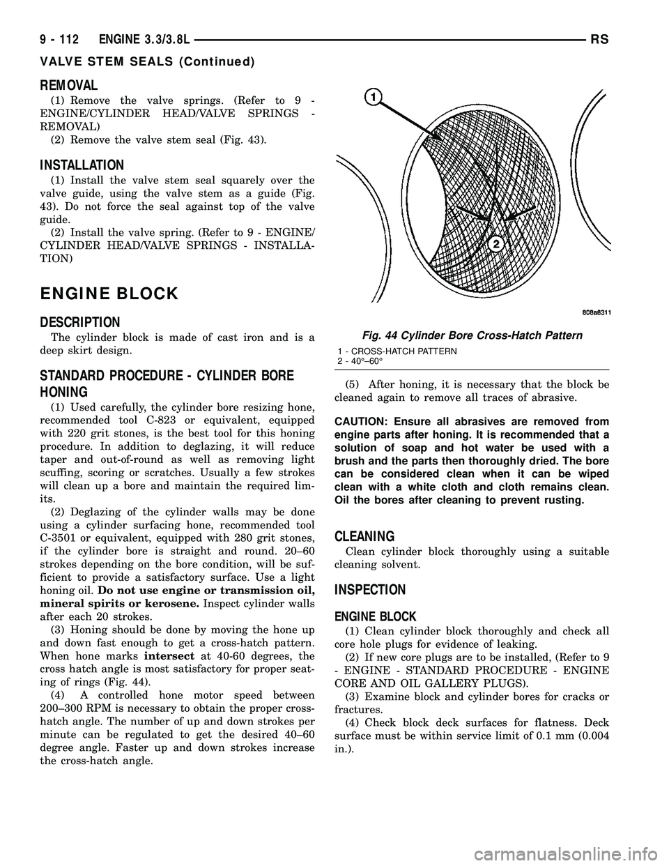
(3) Honing should be done by moving the hone up
and down fast enough to get a cross-hatch pattern.
When hone marksintersectat 40-60 degrees, the
cross hatch angle is most satisfactory for proper seat-
ing of rings (Fig. 44).
(4) A controlled hone motor speed between
200±300 RPM is necessary to obtain the proper cross-
hatch angle. The number of up and down strokes per
minute can be regulated to get the desired 40±60
degree angle. Faster up and down strokes increase
the cross-hatch angle.(5) After honing, it is necessary that the block be
cleaned again to remove all traces of abrasive.
CAUTION: Ensure all abrasives are removed from
engine parts after honing. It is recommended that a
solution of soap and hot water be used with a
brush and the parts then thoroughly dried. The bore
can be considered clean when it can be wiped
clean with a white cloth and cloth remains clean.
Oil the bores after cleaning to prevent rusting.
CLEANING
Clean cylinder block thoroughly using a suitable
cleaning solvent.
INSPECTION
ENGINE BLOCK
(1) Clean cylinder block thoroughly and check all
core hole plugs for evidence of leaking.
(2) If new core plugs are to be installed, (Refer to 9
- ENGINE - STANDARD PROCEDURE - ENGINE
CORE AND OIL GALLERY PLUGS).
(3) Examine block and cylinder bores for cracks or
fractures.
(4) Check block deck surfaces for flatness. Deck
surface must be within service limit of 0.1 mm (0.004
in.).
Fig. 44 Cylinder Bore Cross-Hatch Pattern
1 - CROSS-HATCH PATTERN
2 - 40ɱ60É
9 - 112 ENGINE 3.3/3.8LRS
VALVE STEM SEALS (Continued)
Page 1411 of 2585
Valve lifter noise ranges from light noise to a
heavy click. A light noise is usually caused by exces-
sive leak-down around the unit plunger which will
necessitate replacing the lifter, or by the plunger par-
tially sticking in the lifter body cylinder. A heavy
click is caused either by a lifter check valve not seat-
ing, or by foreign particles becoming wedged between
the plunger and the lifter body causing the plunger
to stick in the down position. This heavy click will be
accompanied by excessive clearance between the
valve stem and rocker arm as valve closes. In either
case, lifter assembly should be removed for inspec-
tion.
REMOVAL
(1) Remove the cylinder head(s). (Refer to 9 -
ENGINE/CYLINDER HEAD - REMOVAL)
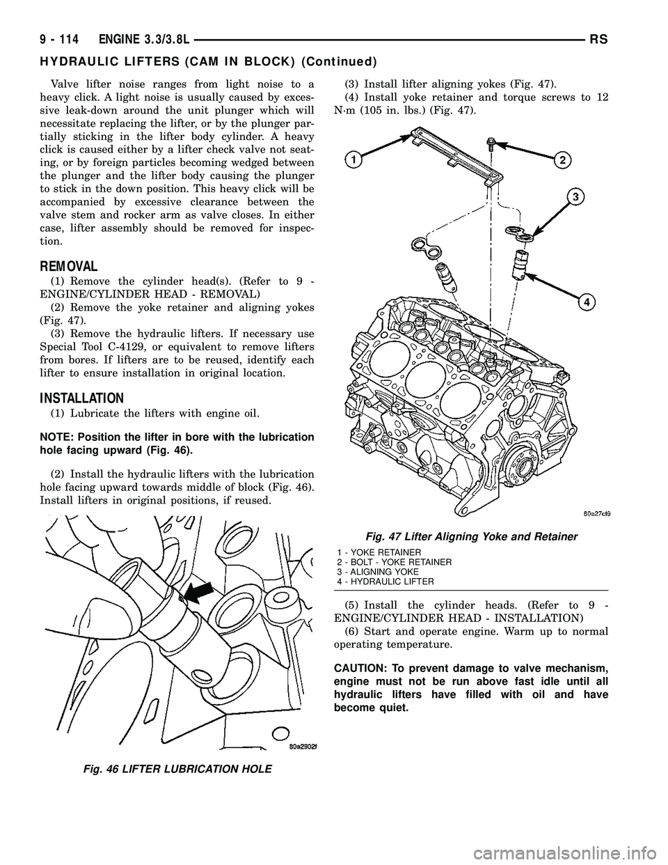
(2) Remove the yoke retainer and aligning yokes
(Fig. 47).
(3) Remove the hydraulic lifters. If necessary use
Special Tool C-4129, or equivalent to remove lifters
from bores. If lifters are to be reused, identify each
lifter to ensure installation in original location.
INSTALLATION
(1) Lubricate the lifters with engine oil.
NOTE: Position the lifter in bore with the lubrication
hole facing upward (Fig. 46).
(2) Install the hydraulic lifters with the lubrication
hole facing upward towards middle of block (Fig. 46).
Install lifters in original positions, if reused.(3) Install lifter aligning yokes (Fig. 47).
(4) Install yoke retainer and torque screws to 12
N´m (105 in. lbs.) (Fig. 47).
(5) Install the cylinder heads. (Refer to 9 -
ENGINE/CYLINDER HEAD - INSTALLATION)
(6) Start and operate engine. Warm up to normal
operating temperature.
CAUTION: To prevent damage to valve mechanism,
engine must not be run above fast idle until all
hydraulic lifters have filled with oil and have
become quiet.
Fig. 46 LIFTER LUBRICATION HOLE
Fig. 47 Lifter Aligning Yoke and Retainer
1 - YOKE RETAINER
2 - BOLT - YOKE RETAINER
3 - ALIGNING YOKE
4 - HYDRAULIC LIFTER
9 - 114 ENGINE 3.3/3.8LRS
HYDRAULIC LIFTERS (CAM IN BLOCK) (Continued)
Page 1438 of 2585
(7) Lower vehicle and install oil dipstick.
(8) Connect negative cable to battery.
(9) Fill crankcase with oil to proper level.
OIL PRESSURE RELIEF VALVE
REMOVAL
(1) Remove oil pan (Refer to 9 - ENGINE/LUBRI-
CATION/OIL PAN - REMOVAL).
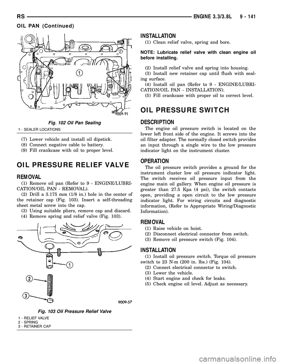
(2) Drill a 3.175 mm (1/8 in.) hole in the center of
the retainer cap (Fig. 103). Insert a self-threading
sheet metal screw into the cap.
(3) Using suitable pliers, remove cap and discard.
(4) Remove spring and relief valve (Fig. 103).
INSTALLATION
(1) Clean relief valve, spring and bore.
NOTE: Lubricate relief valve with clean engine oil
before installing.
(2) Install relief valve and spring into housing.
(3) Install new retainer cap until flush with seal-
ing surface.
(4) Install oil pan (Refer to 9 - ENGINE/LUBRI-
CATION/OIL PAN - INSTALLATION).
(5) Fill crankcase with proper oil to correct level.
OIL PRESSURE SWITCH
DESCRIPTION
The engine oil pressure switch is located on the
lower left front side of the engine. It screws into the
oil filter adapter. The normally closed switch provides
an input through a single wire to the low pressure
indicator light on the instrument cluster.
OPERATION
The oil pressure switch provides a ground for the
instrument cluster low oil pressure indicator light.
The switch receives oil pressure input from the
engine main oil gallery. When engine oil pressure is
greater than 27.5 Kpa (4 psi), the switch contacts
open, providing a open circuit to the low pressure
indicator light. For wiring circuits and diagnostic
information, (Refer to Appropriate Wiring/Diagnostic
Information).
REMOVAL
(1) Raise vehicle on hoist.
(2) Disconnect electrical connector from switch.
(3) Remove oil pressure switch (Fig. 104).
INSTALLATION
(1) Install oil pressure switch. Torque oil pressure
switch to 23 N´m (200 in. lbs.) (Fig. 104).
(2) Connect electrical connector to switch.
(3) Lower the vehicle.
(4) Start engine and check for leaks.
(5) Check engine oil level. Adjust as necessary.
Fig. 102 Oil Pan Sealing
1 - SEALER LOCATIONS
Fig. 103 Oil Pressure Relief Valve
1 - RELIEF VALVE
2 - SPRING
3 - RETAINER CAP
RSENGINE 3.3/3.8L9 - 141
OIL PAN (Continued)
Page 1444 of 2585
²Mounting surface distortion by using a straight-
edge and thickness gauge.
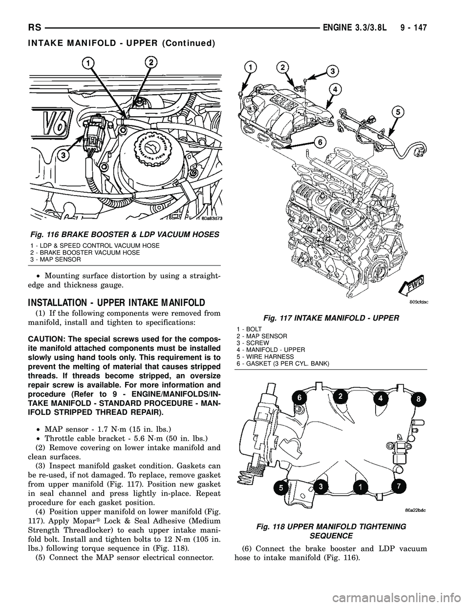
INSTALLATION - UPPER INTAKE MANIFOLD
(1) If the following components were removed from
manifold, install and tighten to specifications:
CAUTION: The special screws used for the compos-
ite manifold attached components must be installed
slowly using hand tools only. This requirement is to
prevent the melting of material that causes stripped
threads. If threads become stripped, an oversize
repair screw is available. For more information and
procedure (Refer to 9 - ENGINE/MANIFOLDS/IN-
TAKE MANIFOLD - STANDARD PROCEDURE - MAN-
IFOLD STRIPPED THREAD REPAIR).
²MAP sensor - 1.7 N´m (15 in. lbs.)
²Throttle cable bracket - 5.6 N´m (50 in. lbs.)
(2) Remove covering on lower intake manifold and
clean surfaces.
(3) Inspect manifold gasket condition. Gaskets can
be re-used, if not damaged. To replace, remove gasket
from upper manifold (Fig. 117). Position new gasket
in seal channel and press lightly in-place. Repeat
procedure for each gasket position.
(4) Position upper manifold on lower manifold (Fig.
117). Apply MopartLock & Seal Adhesive (Medium
Strength Threadlocker) to each upper intake mani-
fold bolt. Install and tighten bolts to 12 N´m (105 in.
lbs.) following torque sequence in (Fig. 118).
(5) Connect the MAP sensor electrical connector.(6) Connect the brake booster and LDP vacuum
hose to intake manifold (Fig. 116).
Fig. 116 BRAKE BOOSTER & LDP VACUUM HOSES
1 - LDP & SPEED CONTROL VACUUM HOSE
2 - BRAKE BOOSTER VACUUM HOSE
3 - MAP SENSOR
Fig. 117 INTAKE MANIFOLD - UPPER
1 - BOLT
2 - MAP SENSOR
3 - SCREW
4 - MANIFOLD - UPPER
5 - WIRE HARNESS
6 - GASKET (3 PER CYL. BANK)
Fig. 118 UPPER MANIFOLD TIGHTENING
SEQUENCE
RSENGINE 3.3/3.8L9 - 147
INTAKE MANIFOLD - UPPER (Continued)
Page 1477 of 2585
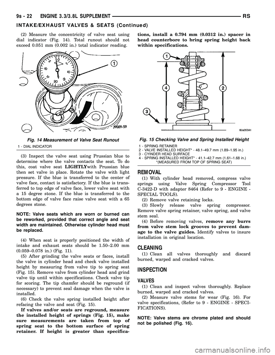
(2) Measure the concentricity of valve seat using
dial indicator (Fig. 14). Total runout should not
exceed 0.051 mm (0.002 in.) total indicator reading.
(3) Inspect the valve seat using Prussian blue to
determine where the valve contacts the seat. To do
this, coat valve seatLIGHTLYwith Prussian blue
then set valve in place. Rotate the valve with light
pressure. If the blue is transferred to the center of
valve face, contact is satisfactory. If the blue is trans-
ferred to top edge of valve face, lower valve seat with
a 15 degree stone. If the blue is transferred to the
bottom edge of valve face raise valve seat with a 65
degrees stone.
NOTE: Valve seats which are worn or burned can
be reworked, provided that correct angle and seat
width are maintained. Otherwise cylinder head must
be replaced.
(4) When seat is properly positioned the width of
intake and exhaust seats should be 1.50±2.00 mm
(0.059±0.078 in.) (Fig. 11).
(5) After grinding the valve seats or faces, install
the valve in cylinder head and check valve installed
height by measuring from valve tip to spring seat
(Fig. 15). Remove valve from cylinder head and grind
valve tip until within specifications. Check valve tip
for scoring. The tip chamfer should be reground (if
necessary) to prevent seal damage when the valve is
installed.
(6) Check the valve spring installed height after
refacing the valve and seat (Fig. 15).
If valves and/or seats are reground, measure
the installed height of springs (Fig. 15), make
sure measurements are taken from top of
spring seat to the bottom surface of spring
retainer. If height is greater than specifica-tions, install a 0.794 mm (0.0312 in.) spacer in
head counterbore to bring spring height back
within specifications.
REMOVAL
(1) With cylinder head removed, compress valve
springs using Valve Spring Compressor Tool
C-3422-D with adapter 8464 (Refer to 9 - ENGINE -
SPECIAL TOOLS).
(2) Remove valve retaining locks.
(3) Slowly release valve spring compressor.
Remove valve spring retainer, valve spring, and valve
stem seal.
(4) Before removing valves,remove any burrs
from valve stem lock grooves to prevent dam-
age to the valve guides.Identify valves to insure
installation in original location.
CLEANING
(1) Clean all valves thoroughly and discard
burned, warped and cracked valves.
INSPECTION
VALVES
(1) Clean and inspect valves thoroughly. Replace
burned, warped and cracked valves.
(2) Measure valve stems for wear (Fig. 16). For
valve specifications, (Refer to 9 - ENGINE - SPECI-
FICATIONS).
NOTE: Valve stems are chrome plated and should
not be polished (Fig. 16).
Fig. 14 Measurement of Valve Seat Runout
1 - DIAL INDICATOR
Fig. 15 Checking Valve and Spring Installed Height
1 - SPRING RETAINER
2 - VALVE INSTALLED HEIGHT* - 48.1±49.7 mm (1.89±1.95 in.)
3 - CYINDER HEAD SURFACE
4 - SPRING INSTALLED HEIGHT* - 41.1±42.7 mm (1.61±1.68 in.)
*(MEASURED FROM TOP OF SPRING SEAT)
9s - 22 ENGINE 3.3/3.8L SUPPLEMENTRS
INTAKE/EXHAUST VALVES & SEATS (Continued)
Page 1482 of 2585
REMOVAL - ROCKER ARMS AND SHAFT
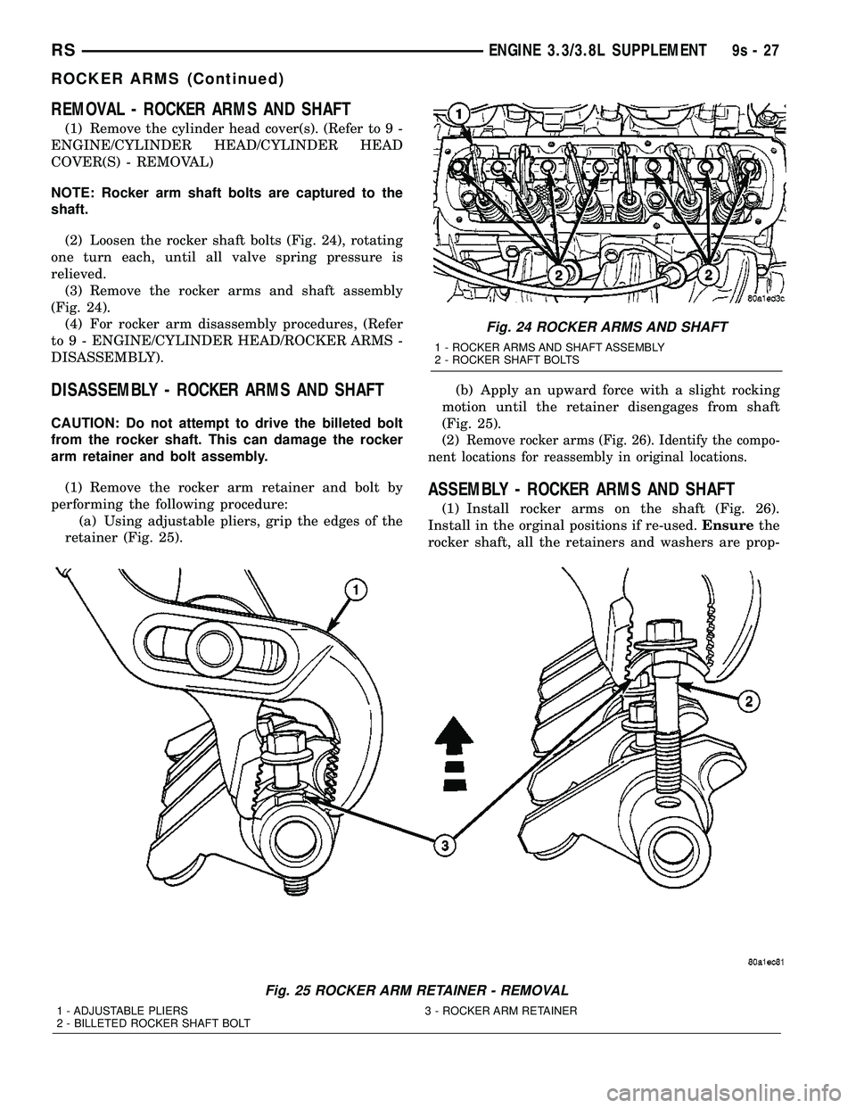
(1) Remove the cylinder head cover(s). (Refer to 9 -
ENGINE/CYLINDER HEAD/CYLINDER HEAD
COVER(S) - REMOVAL)
NOTE: Rocker arm shaft bolts are captured to the
shaft.
(2) Loosen the rocker shaft bolts (Fig. 24), rotating
one turn each, until all valve spring pressure is
relieved.
(3) Remove the rocker arms and shaft assembly
(Fig. 24).
(4) For rocker arm disassembly procedures, (Refer
to 9 - ENGINE/CYLINDER HEAD/ROCKER ARMS -
DISASSEMBLY).
DISASSEMBLY - ROCKER ARMS AND SHAFT
CAUTION: Do not attempt to drive the billeted bolt
from the rocker shaft. This can damage the rocker
arm retainer and bolt assembly.
(1) Remove the rocker arm retainer and bolt by
performing the following procedure:
(a) Using adjustable pliers, grip the edges of the
retainer (Fig. 25).(b) Apply an upward force with a slight rocking
motion until the retainer disengages from shaft
(Fig. 25).
(2)
Remove rocker arms (Fig. 26). Identify the compo-
nent locations for reassembly in original locations.
ASSEMBLY - ROCKER ARMS AND SHAFT
(1) Install rocker arms on the shaft (Fig. 26).
Install in the orginal positions if re-used.Ensurethe
rocker shaft, all the retainers and washers are prop-
Fig. 24 ROCKER ARMS AND SHAFT
1 - ROCKER ARMS AND SHAFT ASSEMBLY
2 - ROCKER SHAFT BOLTS
Fig. 25 ROCKER ARM RETAINER - REMOVAL
1 - ADJUSTABLE PLIERS 3 - ROCKER ARM RETAINER
2 - BILLETED ROCKER SHAFT BOLT
RSENGINE 3.3/3.8L SUPPLEMENT9s-27
ROCKER ARMS (Continued)
Page 1491 of 2585
Visually inspect the catalytic converter element by
using a borescope or equivalent. Remove oxygen sen-
sor(s) and insert borescope. If borescope is not avail-
able, remove converter and inspect element using a
flashlight. Inspect element for cracked or melted sub-
strate.
NOTE: Before replacing a catalytic converter, deter-
mine the root cause of failure. Most catalytic con-
verter failures are caused by air, fuel or ignition
problems. (Refer to Appropriate Diagnostic Informa-
tion) for test procedures.
INSTALLATION
(1) Position new gasket onto the manifold flange
and install catalytic converter (Fig. 5). Tighten fas-
teners to 37 N´m (325 in. lbs.).
NOTE: Be careful not to twist or kink the oxygen
sensor wires.
(2) Install (if removed) and connect the down-
stream oxygen sensor (Fig. 4).
(3) Install the muffler/resonator assembly. (Refer
to 11 - EXHAUST SYSTEM/MUFFLER - INSTALLA-
TION)
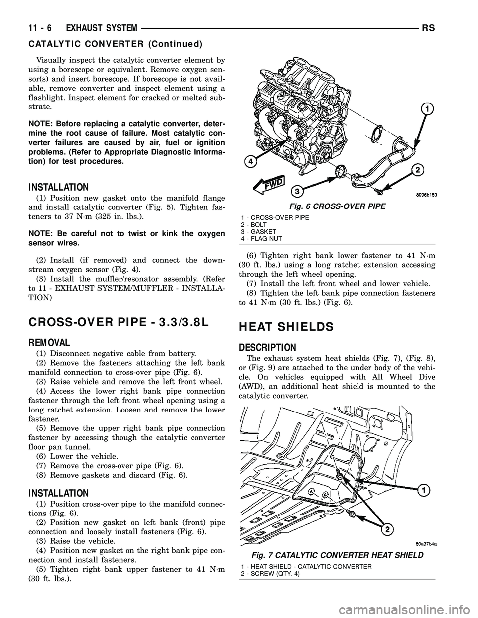
CROSS-OVER PIPE - 3.3/3.8L
REMOVAL
(1) Disconnect negative cable from battery.
(2) Remove the fasteners attaching the left bank
manifold connection to cross-over pipe (Fig. 6).
(3) Raise vehicle and remove the left front wheel.
(4) Access the lower right bank pipe connection
fastener through the left front wheel opening using a
long ratchet extension. Loosen and remove the lower
fastener.
(5) Remove the upper right bank pipe connection
fastener by accessing though the catalytic converter
floor pan tunnel.
(6) Lower the vehicle.
(7) Remove the cross-over pipe (Fig. 6).
(8) Remove gaskets and discard (Fig. 6).
INSTALLATION
(1) Position cross-over pipe to the manifold connec-
tions (Fig. 6).
(2) Position new gasket on left bank (front) pipe
connection and loosely install fasteners (Fig. 6).
(3) Raise the vehicle.
(4) Position new gasket on the right bank pipe con-
nection and install fasteners.
(5) Tighten right bank upper fastener to 41 N´m
(30 ft. lbs.).(6) Tighten right bank lower fastener to 41 N´m
(30 ft. lbs.) using a long ratchet extension accessing
through the left wheel opening.
(7) Install the left front wheel and lower vehicle.
(8) Tighten the left bank pipe connection fasteners
to 41 N´m (30 ft. lbs.) (Fig. 6).
HEAT SHIELDS
DESCRIPTION
The exhaust system heat shields (Fig. 7), (Fig. 8),
or (Fig. 9) are attached to the under body of the vehi-
cle. On vehicles equipped with All Wheel Dive
(AWD), an additional heat shield is mounted to the
catalytic converter.
Fig. 6 CROSS-OVER PIPE
1 - CROSS-OVER PIPE
2 - BOLT
3 - GASKET
4 - FLAG NUT
Fig. 7 CATALYTIC CONVERTER HEAT SHIELD
1 - HEAT SHIELD - CATALYTIC CONVERTER
2 - SCREW (QTY. 4)
11 - 6 EXHAUST SYSTEMRS
CATALYTIC CONVERTER (Continued)