2004 CHRYSLER VOYAGER oil pressure
[x] Cancel search: oil pressurePage 2066 of 2585
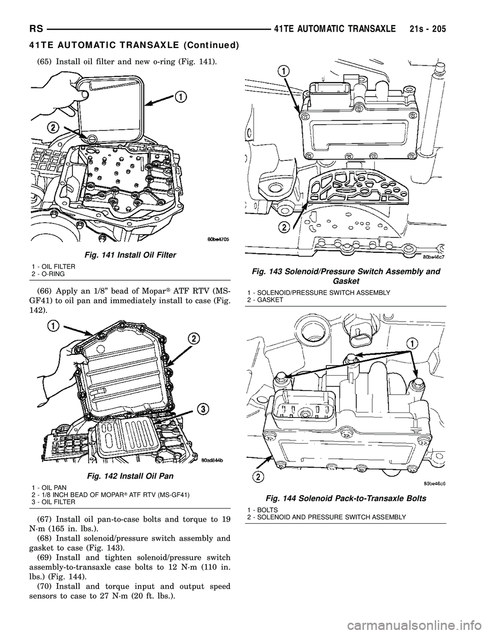
(65) Install oil filter and new o-ring (Fig. 141).
(66) Apply an 1/8º bead of MopartATF RTV (MS-
GF41) to oil pan and immediately install to case (Fig.
142).
(67) Install oil pan-to-case bolts and torque to 19
N´m (165 in. lbs.). (68) Install solenoid/pressure switch assembly and
gasket to case (Fig. 143). (69) Install and tighten solenoid/pressure switch
assembly-to-transaxle case bolts to 12 N´m (110 in.
lbs.) (Fig. 144). (70) Install and torque input and output speed
sensors to case to 27 N´m (20 ft. lbs.).
Fig. 141 Install Oil Filter
1 - OIL FILTER
2 - O-RING
Fig. 142 Install Oil Pan
1 - OIL PAN
2 - 1/8 INCH BEAD OF MOPAR TATF RTV (MS-GF41)
3 - OIL FILTER
Fig. 143 Solenoid/Pressure Switch Assembly and
Gasket
1 - SOLENOID/PRESSURE SWITCH ASSEMBLY
2 - GASKET
Fig. 144 Solenoid Pack-to-Transaxle Bolts
1 - BOLTS
2 - SOLENOID AND PRESSURE SWITCH ASSEMBLY
RS 41TE AUTOMATIC TRANSAXLE21s - 205
41TE AUTOMATIC TRANSAXLE (Continued)
Page 2402 of 2585
required. If the test is failed, the snowflake icon and
the DELAY text will continue to blink across ignition
cycles until the vehicle has been driven for greater
than 1.6 km (8 miles).
DIAGNOSIS AND TESTING - A/C
PERFORMANCE TEST
The A/C system is designed to remove heat and
humidity from the air entering the passenger com-
partment. The evaporator, located in the HVAC hous-
ing, is cooled to temperatures near the freezing point.
As warm damp air passes over the fins in the A/C
evaporator, moisture in the air condenses to water,
dehumidifying the air. Condensation on the evapora-
tor fins reduces the evaporators ability to absorb
heat. During periods of high heat and humidity, an
A/C system will be less effective. With the instru-
ment control set to recirculation mode, only air from
the passenger compartment passes through the A/C
evaporator. As the passenger compartment air dehu-
midifies, A/C performance levels rise.
Humidity has an important bearing on the temper-
ature of the air delivered to the interior of the vehi-
cle. It is important to understand the effect that
humidity has on the performance of the A/C system.
When humidity is high, the A/C evaporator has to
perform a double duty. It must lower the air temper-
ature, and it must lower the temperature of the
moisture in the air that condenses on the evaporator
fins. Condensing the moisture in the air transfers
heat energy into the evaporator fins and tubing. This
reduces the amount of heat the A/C evaporator can
absorb from the air. High humidity greatly reduces
the ability of the A/C evaporator to lower the temper-
ature of the air.
However, evaporator capacity used to reduce the
amount of moisture in the air is not wasted. Wring-
ing some of the moisture out of the air entering the
vehicle adds to the comfort of the passengers.
Although, an owner may expect too much from their
A/C system on humid days. A performance test is the
best way to determine whether the system is per-
forming up to design standards. This test also pro-
vides valuable clues as to the possible cause of
trouble with the A/C system. The ambient air tem-perature in the location where the vehicle will be
tested must be a minimum of 21É C (70É F) for this
test.
PERFORMANCE TEST PROCEDURE
WARNING: REFER TO THE APPLICABLE WARN-
INGS AND CAUTIONS FOR THIS SYSTEM BEFORE
PERFORMING THE FOLLOWING OPERATION (Refer
to 24 - HEATING & AIR CONDITIONING/PLUMBING -
FRONT - WARNING - A/C PLUMBING) and (Refer to
24 - HEATING & AIR CONDITIONING/PLUMBING -
FRONT - CAUTION - A/C PLUMBING).
NOTE: When connecting the service equipment
coupling to the line fitting, verify that the valve of
the coupling is fully closed. This will reduce the
amount of effort required to make the connection.
(1) Connect a tachometer and a manifold gauge
set.
(2) Set the mode control to the Recirculation Mode
position, the temperature control to the full cool posi-
tion and the blower to the highest speed position.
(3) Start the engine and hold at 1,000 rpm with
the A/C compressor clutch engaged.
(4) The engine should be warmed up to operating
temperature with the doors closed and windows
open.
(5) Insert a thermometer in the driver's side center
panel A/C-heater outlet and operate the engine for
five minutes.
(6) If the compressor clutch does not engage, pro-
ceed with diagnosis of the compressor clutch coil.
(Refer to 24 - HEATING & AIR CONDITIONING/
CONTROLS - FRONT/COMPRESSOR CLUTCH
COIL - DIAGNOSIS AND TESTING).
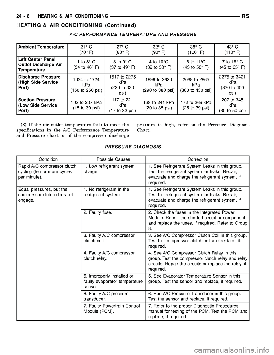
(7) With the A/C compressor clutch engaged, com-
pare the air temperature at the center panel outlet
and the compressor discharge pressure to the A/C
Performance Temperature and Pressure chart. The
compressor clutch may cycle, depending upon the
ambient temperature and humidity. If the clutch
cycles, use the readings obtained before the clutch
disengaged.
RSHEATING & AIR CONDITIONING24-7
HEATING & AIR CONDITIONING (Continued)
Page 2403 of 2585
A/C PERFORMANCE TEMPERATURE AND PRESSURE
Ambient Temperature21É C
(70É F)27É C
(80É F)32É C
(90É F)38É C
(100É F)43É C
(110É F)
Left Center Panel
Outlet Discharge Air
Temperature1to8ÉC
(34 to 46É F)3to9ÉC
(37 to 49É F)4 to 10ÉC
(39 to 50É F)6to11ÉC
(43 to 52É F)7 to 18É C
(45 to 65É F)
Discharge Pressure
(High Side Service
Port)1034 to 1724
kPa
(150 to 250 psi)1517 to 2275
kPa
(220 to 330
psi)1999 to 2620
kPa
(290 to 380 psi)2068 to 2965
kPa
(300 to 430 psi)2275 to 3421
kPa
(330 to 450
psi)
Suction Pressure
(Low Side Service
Port)103 to 207 kPa
(15 to 30 psi)117to221
kPa
(17 to 32 psi)138 to 241 kPa
(20 to 35 psi)172 to 269 kPa
(25 to 39 psi)207 to 345
kPa
(30 to 50 psi)
(8) If the air outlet temperature fails to meet the
specifications in the A/C Performance Temperature
and Pressure chart, or if the compressor dischargepressure is high, refer to the Pressure Diagnosis
Chart.
PRESSURE DIAGNOSIS
Condition Possible Causes Correction
Rapid A/C compressor clutch
cycling (ten or more cycles
per minute).1. Low refrigerant system
charge.1. See Refrigerant System Leaks in this group.
Test the refrigerant system for leaks. Repair,
evacuate and charge the refrigerant system, if
required.
Equal pressures, but the
compressor clutch does not
engage.1. No refrigerant in the
refrigerant system.1. See Refrigerant System Leaks in this group.
Test the refrigerant system for leaks. Repair,
evacuate and charge the refrigerant system, if
required.
2. Faulty fuse. 2. Check the fuses in the Integrated Power
Module. Repair the shorted circuit or component
and replace the fuses, if required. Refer to Group
8.
3. Faulty A/C compressor
clutch coil.3. See A/C Compressor Clutch Coil in this group.
Test the compressor clutch coil and replace, if
required.
4. Faulty A/C compressor
clutch relay.4. See A/C Compressor Clutch Relay in this
group. Test the compressor clutch relay and relay
circuits. Repair the circuits or replace the relay, if
required.
5. Improperly installed or
faulty evaporator temperature
sensor.5. See Evaporator Temperature Sensor in this
group. Test the sensor and replace, if required.
6. Faulty A/C pressure
transducer.6. See A/C Pressure Transducer in this group.
Test the sensor and replace, if required.
7. Faulty Powertrain Control
Module (PCM).7. Refer to the proper Diagnostic Procedures
manual for testing of the PCM. Test the PCM and
replace, if required.
24 - 8 HEATING & AIR CONDITIONINGRS
HEATING & AIR CONDITIONING (Continued)
Page 2404 of 2585
Condition Possible Causes Correction
Normal pressures, but A/C
Performance Test air
temperatures at center panel
outlet are too high.1. Excessive refrigerant oil in
system.1. See Refrigerant Oil Level in this group.
Recover the refrigerant from the refrigerant
system and inspect the refrigerant oil content.
Restore the refrigerant oil to the proper level, if
required.
2. Blend door actuator
improperly installed or faulty.2. See Blend Door Actuator in this group. Inspect
the actuator for proper operation and replace, if
required.
3. Blend door inoperative or
sealing improperly.3. See HVAC Housing in this group. Inspect the
blend door for proper operation and sealing.
Repair if required.
The low side pressure is
normal or slightly low, and the
high side pressure is too low.1. Low refrigerant system
charge.1. See Refrigerant System Leaks in this group.
Test the refrigerant system for leaks. Repair,
evacuate and charge the refrigerant system, if
required.
2. Refrigerant flow through
the A/C evaporator is
restricted.2. See A/C Evaporator in this group. Replace the
restricted A/C evaporator, if required.
3. Faulty A/C compressor. 3. See A/C Compressor in this group. Replace
the compressor, if required.
The low side pressure is
normal or slightly high, and
the high side pressure is too
high.1. A/C condenser air flow
restricted.1. Check the A/C condenser for damaged fins,
foreign objects obstructing air flow through the
condenser fins, and missing or improperly
installed air seals. Clean, repair, or replace
components as required.
2. Refrigerant flow through
the receiver/drier is
restricted.2. See Receiver/Drier in this group. Replace the
restricted receiver/drier, if required.
3. Inoperative radiator
cooling fan.3. Test the radiator cooling fan and replace, if
required. Refer to Group 7.
4. Refrigerant system
overcharged.4. See Refrigerant System Charge in this group.
Recover the refrigerant from the refrigerant
system. Charge the refrigerant system to the
proper level, if required.
5. Air in the refrigerant
system.5. See Refrigerant System Leaks in this group.
Test the refrigerant system for leaks. Repair,
evacuate and charge the refrigerant system, if
required.
6. Engine overheating. 6. Test the engine cooling system and repair, if
required. Refer to Group 7.
The low side pressure is too
high, and the high side
pressure is too low.1. Accessory drive belt
slipping.1. Inspect the accessory drive belt condition and
tension. Tighten or replace the accessory drive
belt, if required. Refer to Group 7.
2. Faulty A/C expansion
valve.2. See A/C Expansion Valve in this group.
Replace the valve, if required.
3. Faulty A/C compressor. 3. See A/C Compressor in this group. Replace
the compressor, if required.
RSHEATING & AIR CONDITIONING24-9
HEATING & AIR CONDITIONING (Continued)
Page 2406 of 2585
MECHANICAL PROBLEMS
Possible causes of insufficient heat due to mechan-
ical problems are as follows:
²Obstructed cowl air intake.
²Obstructed heater system outlets.
²Blend door not functioning properly.
TEMPERATURE CONTROL
If the heater outlet air temperature cannot be
adjusted with the temperature control knob on the
A/C-heater control panel, the following could require
service:
²Blend door binding.²Faulty blend door actuator.
²Faulty A/C-heater control.
²Faulty related wiring harness or connectors.
²Improper engine coolant temperature.
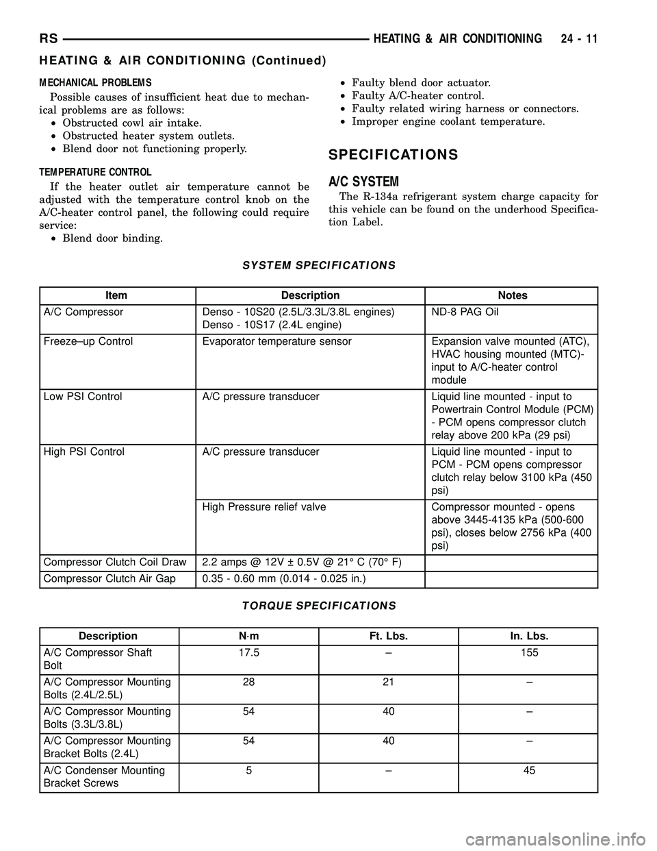
SPECIFICATIONS
A/C SYSTEM
The R-134a refrigerant system charge capacity for
this vehicle can be found on the underhood Specifica-
tion Label.
SYSTEM SPECIFICATIONS
Item Description Notes
A/C Compressor Denso - 10S20 (2.5L/3.3L/3.8L engines)
Denso - 10S17 (2.4L engine)ND-8 PAG Oil
Freeze±up Control Evaporator temperature sensor Expansion valve mounted (ATC),
HVAC housing mounted (MTC)-
input to A/C-heater control
module
Low PSI Control A/C pressure transducer Liquid line mounted - input to
Powertrain Control Module (PCM)
- PCM opens compressor clutch
relay above 200 kPa (29 psi)
High PSI Control A/C pressure transducer Liquid line mounted - input to
PCM - PCM opens compressor
clutch relay below 3100 kPa (450
psi)
High Pressure relief valve Compressor mounted - opens
above 3445-4135 kPa (500-600
psi), closes below 2756 kPa (400
psi)
Compressor Clutch Coil Draw 2.2 amps @ 12V 0.5V @ 21É C (70É F)
Compressor Clutch Air Gap 0.35 - 0.60 mm (0.014 - 0.025 in.)
TORQUE SPECIFICATIONS
Description N´m Ft. Lbs. In. Lbs.
A/C Compressor Shaft
Bolt17.5 ± 155
A/C Compressor Mounting
Bolts (2.4L/2.5L)28 21 ±
A/C Compressor Mounting
Bolts (3.3L/3.8L)54 40 ±
A/C Compressor Mounting
Bracket Bolts (2.4L)54 40 ±
A/C Condenser Mounting
Bracket Screws5±45
RSHEATING & AIR CONDITIONING24-11
HEATING & AIR CONDITIONING (Continued)
Page 2409 of 2585
CONTROLS - FRONT
TABLE OF CONTENTS
page page
A/C COMPRESSOR CLUTCH/COIL
DESCRIPTION.........................15
OPERATION...........................15
DIAGNOSIS AND TESTING - A/C
COMPRESSOR CLUTCH COIL...........15
REMOVAL.............................16
INSPECTION..........................17
INSTALLATION.........................17
A/C COMPRESSOR CLUTCH RELAY
DESCRIPTION.........................19
OPERATION...........................19
REMOVAL.............................20
INSTALLATION.........................20
A/C HEATER CONTROL
DESCRIPTION.........................20
STANDARD PROCEDURE - A/C-HEATER
CONTROL CALIBRATION...............20
REMOVAL.............................21
INSTALLATION.........................21
A/C PRESSURE TRANSDUCER
DESCRIPTION.........................21
OPERATION...........................21
DIAGNOSIS AND TESTING - A/C PRESSURE
TRANSDUCER.......................22
REMOVAL.............................22
INSTALLATION.........................22
BLEND DOOR ACTUATOR
DESCRIPTION.........................23
OPERATION...........................23
REMOVAL.............................23
INSTALLATION.........................23
BLOWER MOTOR RELAY
DESCRIPTION.........................24
OPERATION...........................24
REMOVAL.............................25
INSTALLATION.........................25
BLOWER MOTOR RESISTOR BLOCK
DESCRIPTION.........................26OPERATION...........................26
DIAGNOSIS AND TESTING - BLOWER
MOTOR RESISTOR BLOCK..............26
REMOVAL.............................26
INSTALLATION.........................27
EVAPORATOR TEMPERATURE SENSOR
DESCRIPTION.........................27
OPERATION...........................28
REMOVAL
REMOVAL - AUTOMATIC TEMPERATURE
CONTROL (ATC)......................28
REMOVAL - MANUAL TEMPERATURE
CONTROL (MTC)......................29
INSTALLATION
INSTALLATION - AUTOMATIC
TEMPERATURE CONTROL (ATC).........29
INSTALLATION - MANUAL TEMPERATURE
CONTROL (MTC)......................29
INFRARED TEMPERATURE SENSOR
DESCRIPTION.........................29
OPERATION...........................29
MODE DOOR ACTUATOR
DESCRIPTION.........................30
OPERATION...........................30
REMOVAL.............................30
INSTALLATION.........................31
POWER MODULE - BLOWER MOTOR
DESCRIPTION.........................31
OPERATION...........................31
REMOVAL.............................31
INSTALLATION.........................32
RECIRCULATION DOOR ACTUATOR
DESCRIPTION.........................32
OPERATION...........................32
REMOVAL.............................33
INSTALLATION.........................33
24 - 14 CONTROLS - FRONTRS
Page 2410 of 2585
A/C COMPRESSOR CLUTCH/
COIL
DESCRIPTION
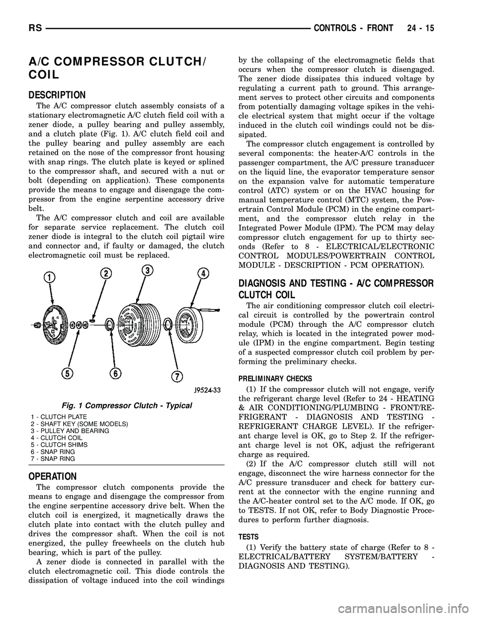
The A/C compressor clutch assembly consists of a
stationary electromagnetic A/C clutch field coil with a
zener diode, a pulley bearing and pulley assembly,
and a clutch plate (Fig. 1). A/C clutch field coil and
the pulley bearing and pulley assembly are each
retained on the nose of the compressor front housing
with snap rings. The clutch plate is keyed or splined
to the compressor shaft, and secured with a nut or
bolt (depending on application). These components
provide the means to engage and disengage the com-
pressor from the engine serpentine accessory drive
belt.
The A/C compressor clutch and coil are available
for separate service replacement. The clutch coil
zener diode is integral to the clutch coil pigtail wire
and connector and, if faulty or damaged, the clutch
electromagnetic coil must be replaced.
OPERATION
The compressor clutch components provide the
means to engage and disengage the compressor from
the engine serpentine accessory drive belt. When the
clutch coil is energized, it magnetically draws the
clutch plate into contact with the clutch pulley and
drives the compressor shaft. When the coil is not
energized, the pulley freewheels on the clutch hub
bearing, which is part of the pulley.
A zener diode is connected in parallel with the
clutch electromagnetic coil. This diode controls the
dissipation of voltage induced into the coil windingsby the collapsing of the electromagnetic fields that
occurs when the compressor clutch is disengaged.
The zener diode dissipates this induced voltage by
regulating a current path to ground. This arrange-
ment serves to protect other circuits and components
from potentially damaging voltage spikes in the vehi-
cle electrical system that might occur if the voltage
induced in the clutch coil windings could not be dis-
sipated.
The compressor clutch engagement is controlled by
several components: the heater-A/C controls in the
passenger compartment, the A/C pressure transducer
on the liquid line, the evaporator temperature sensor
on the expansion valve for automatic temperature
control (ATC) system or on the HVAC housing for
manual temperature control (MTC) system, the Pow-
ertrain Control Module (PCM) in the engine compart-
ment, and the compressor clutch relay in the
Integrated Power Module (IPM). The PCM may delay
compressor clutch engagement for up to thirty sec-
onds (Refer to 8 - ELECTRICAL/ELECTRONIC
CONTROL MODULES/POWERTRAIN CONTROL
MODULE - DESCRIPTION - PCM OPERATION).
DIAGNOSIS AND TESTING - A/C COMPRESSOR
CLUTCH COIL
The air conditioning compressor clutch coil electri-
cal circuit is controlled by the powertrain control
module (PCM) through the A/C compressor clutch
relay, which is located in the integrated power mod-
ule (IPM) in the engine compartment. Begin testing
of a suspected compressor clutch coil problem by per-
forming the preliminary checks.
PRELIMINARY CHECKS
(1) If the compressor clutch will not engage, verify
the refrigerant charge level (Refer to 24 - HEATING
& AIR CONDITIONING/PLUMBING - FRONT/RE-
FRIGERANT - DIAGNOSIS AND TESTING -
REFRIGERANT CHARGE LEVEL). If the refriger-
ant charge level is OK, go to Step 2. If the refriger-
ant charge level is not OK, adjust the refrigerant
charge as required.
(2) If the A/C compressor clutch still will not
engage, disconnect the wire harness connector for the
A/C pressure transducer and check for battery cur-
rent at the connector with the engine running and
the A/C-heater control set to the A/C mode. If OK, go
to TESTS. If not OK, refer to Body Diagnostic Proce-
dures to perform further diagnosis.
TESTS
(1) Verify the battery state of charge (Refer to 8 -
ELECTRICAL/BATTERY SYSTEM/BATTERY -
DIAGNOSIS AND TESTING).
Fig. 1 Compressor Clutch - Typical
1 - CLUTCH PLATE
2 - SHAFT KEY (SOME MODELS)
3 - PULLEY AND BEARING
4 - CLUTCH COIL
5 - CLUTCH SHIMS
6 - SNAP RING
7 - SNAP RING
RSCONTROLS - FRONT24-15
Page 2414 of 2585
COOLING/ACCESSORY DRIVE/DRIVE BELTS -
3.3L/3.8L - INSTALLATION).
(15) Lower the vehicle.
(16) Reconnect the battery negative cable.
CLUTCH BREAK-IN
After a new compressor clutch has been installed,
cycle the compressor clutch approximately twenty
times (five seconds on, then five seconds off). During
this procedure, set the A/C-heater control to the A/C
Recirculation Mode, the blower motor switch in the
highest speed position, and the engine speed at 1500
to 2000 rpm. This procedure (burnishing) will seat
the opposing friction surfaces and provide a higher
compressor clutch torque capability.
A/C COMPRESSOR CLUTCH
RELAY
DESCRIPTION
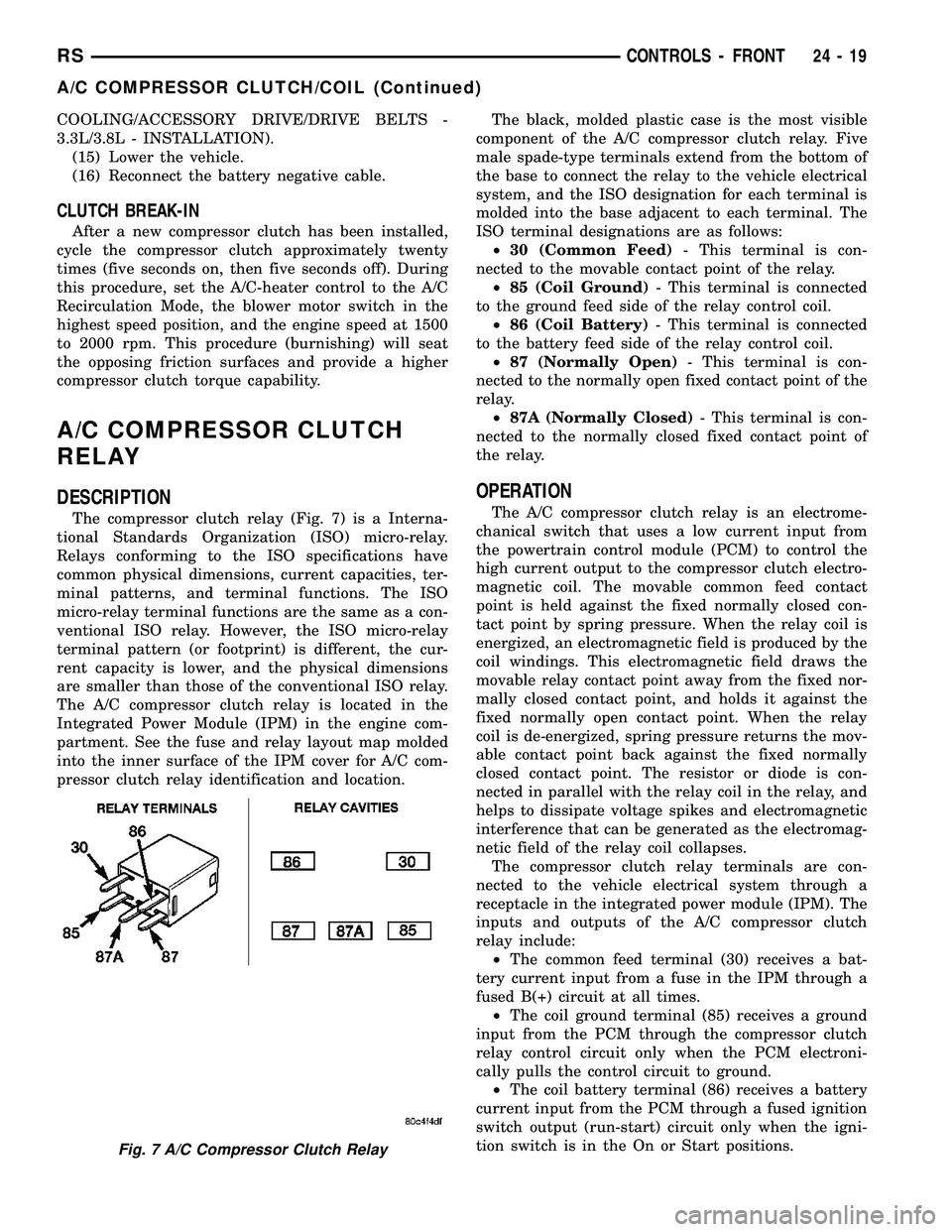
The compressor clutch relay (Fig. 7) is a Interna-
tional Standards Organization (ISO) micro-relay.
Relays conforming to the ISO specifications have
common physical dimensions, current capacities, ter-
minal patterns, and terminal functions. The ISO
micro-relay terminal functions are the same as a con-
ventional ISO relay. However, the ISO micro-relay
terminal pattern (or footprint) is different, the cur-
rent capacity is lower, and the physical dimensions
are smaller than those of the conventional ISO relay.
The A/C compressor clutch relay is located in the
Integrated Power Module (IPM) in the engine com-
partment. See the fuse and relay layout map molded
into the inner surface of the IPM cover for A/C com-
pressor clutch relay identification and location.The black, molded plastic case is the most visible
component of the A/C compressor clutch relay. Five
male spade-type terminals extend from the bottom of
the base to connect the relay to the vehicle electrical
system, and the ISO designation for each terminal is
molded into the base adjacent to each terminal. The
ISO terminal designations are as follows:
²30 (Common Feed)- This terminal is con-
nected to the movable contact point of the relay.
²85 (Coil Ground)- This terminal is connected
to the ground feed side of the relay control coil.
²86 (Coil Battery)- This terminal is connected
to the battery feed side of the relay control coil.
²87 (Normally Open)- This terminal is con-
nected to the normally open fixed contact point of the
relay.
²87A (Normally Closed)- This terminal is con-
nected to the normally closed fixed contact point of
the relay.
OPERATION
The A/C compressor clutch relay is an electrome-
chanical switch that uses a low current input from
the powertrain control module (PCM) to control the
high current output to the compressor clutch electro-
magnetic coil. The movable common feed contact
point is held against the fixed normally closed con-
tact point by spring pressure. When the relay coil is
energized, an electromagnetic field is produced by the
coil windings. This electromagnetic field draws the
movable relay contact point away from the fixed nor-
mally closed contact point, and holds it against the
fixed normally open contact point. When the relay
coil is de-energized, spring pressure returns the mov-
able contact point back against the fixed normally
closed contact point. The resistor or diode is con-
nected in parallel with the relay coil in the relay, and
helps to dissipate voltage spikes and electromagnetic
interference that can be generated as the electromag-
netic field of the relay coil collapses.
The compressor clutch relay terminals are con-
nected to the vehicle electrical system through a
receptacle in the integrated power module (IPM). The
inputs and outputs of the A/C compressor clutch
relay include:
²The common feed terminal (30) receives a bat-
tery current input from a fuse in the IPM through a
fused B(+) circuit at all times.
²The coil ground terminal (85) receives a ground
input from the PCM through the compressor clutch
relay control circuit only when the PCM electroni-
cally pulls the control circuit to ground.
²The coil battery terminal (86) receives a battery
current input from the PCM through a fused ignition
switch output (run-start) circuit only when the igni-
tion switch is in the On or Start positions.
Fig. 7 A/C Compressor Clutch Relay
RSCONTROLS - FRONT24-19
A/C COMPRESSOR CLUTCH/COIL (Continued)