2004 CHRYSLER VOYAGER oil pressure
[x] Cancel search: oil pressurePage 1848 of 2585
MANUAL VALVE
The manual valve is operated by the mechanical
shift linkage. Its primary responsibility is to send
line pressure to the appropriate hydraulic circuits
and solenoids. The valve has three operating ranges
or positions.
CONVERTER CLUTCH SWITCH VALVE
The main responsibility of the converter clutch
switch valve is to control hydraulic pressure applied
to the front (off) side of the converter clutch piston.
Line pressure from the regulator valve is fed to the
torque converter regulator valve, where it passes
through the valve, and is slightly regulated. The
pressure is then directed to the converter clutch
switch valve and to the front side of the converter
clutch piston. This pressure pushes the piston back
and disengages the converter clutch.
CONVERTER CLUTCH CONTROL VALVE
The converter clutch control valve controls the
back (on) side of the torque converter clutch. When
the PCM/TCM energizes or modulates the LR/CC
solenoid to apply the converter clutch piston, both
the converter clutch control valve and the converter
control valve move, allowing pressure to be applied to
the back side of the clutch.
T/C REGULATOR VALVE
The torque converter regulator valve slightly regu-
lates the flow of fluid to the torque converter.
LOW/REVERSE SWITCH VALVE
The low/reverse clutch is applied from different
sources, depending on whether low (1st) gear or
reverse is selected. The low/reverse switch valve
alternates positions depending on from which direc-
tion fluid pressure is applied. By design, when the
valve is shifted by fluid pressure from one channel,
the opposing channel is blocked. The switch valve
alienates the possibility of a sticking ball check, thus
providing consistent application of the low/reverse
clutch under all operating conditions.
REMOVAL
NOTE: If valve body is replaced or reconditioned,
the TCM Quick Learn Procedure must be per-
formed. (Refer to 8 - ELECTRICAL/ELECTRONIC
CONTROL MODULES/TRANSMISSION CONTROL
MODULE - STANDARD PROCEDURE)(1) Disconnect battery negative cable.
(2) Disconnect gearshift cable from manual valve
lever.
(3) Remove manual valve lever from manual shaft.
(4) Raise vehicle on hoist.
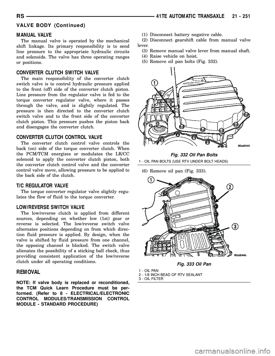
(5) Remove oil pan bolts (Fig. 332).
(6) Remove oil pan (Fig. 333).
Fig. 332 Oil Pan Bolts
1 - OIL PAN BOLTS (USE RTV UNDER BOLT HEADS)
Fig. 333 Oil Pan
1 - OIL PAN
2 - 1/8 INCH BEAD OF RTV SEALANT
3 - OIL FILTER
RS41TE AUTOMATIC TRANSAXLE21 - 251
VALVE BODY (Continued)
Page 1885 of 2585
40TE AUTOMATIC TRANSAXLE
TABLE OF CONTENTS
page page
40TE AUTOMATIC TRANSAXLE DESCRIPTION .........................25
OPERATION ...........................27
DIAGNOSIS AND TESTING DIAGNOSIS AND TESTING - 4XTETRANSAXLE GENERAL DIAGNOSIS .......27
DIAGNOSIS AND TESTING - ROAD TEST . . . 27
DIAGNOSIS AND TESTING - HYDRAULIC PRESSURE TESTS ....................28
DIAGNOSIS AND TESTING - CLUTCH AIR PRESSURE TESTS ....................30
DIAGNOSIS AND TESTING - TORQUE CONVERTER HOUSING FLUID LEAKAGE . . . 31
REMOVAL .............................31
DISASSEMBLY .........................34
ASSEMBLY ............................51
INSTALLATION .........................73
SCHEMATICS AND DIAGRAMS 4XTE TRANSAXLE HYDRAULICSCHEMATICS ........................75
SPECIFICATIONS - 41TE TRANSAXLE .......87
SPECIAL TOOLS .......................89
ACCUMULATOR DESCRIPTION .........................94
OPERATION ...........................94
DRIVING CLUTCHES DESCRIPTION .........................95
OPERATION ...........................95
FINAL DRIVE DESCRIPTION .........................95
OPERATION ...........................96
DISASSEMBLY .........................96
ASSEMBLY ............................99
ADJUSTMENTS DIFFERENTIAL BEARING PRELOADMEASUREMENT AND ADJUSTMENT ......100
FLUID STANDARD PROCEDURE FLUID LEVEL AND CONDITION CHECK . . . 102
STANDARD PROCEDURE - FLUID ANDFILTER SERVICE .....................104
GEAR SHIFT CABLE REMOVAL ............................105
HOLDING CLUTCHES DESCRIPTION ........................106
OPERATION ..........................106
INPUT CLUTCH ASSEMBLY DISASSEMBLY ........................107
ASSEMBLY ...........................116 OIL PUMP
DESCRIPTION ........................131
OPERATION ..........................131
DISASSEMBLY ........................131
ASSEMBLY ...........................132
PLANETARY GEARTRAIN DESCRIPTION ........................132
OPERATION ..........................132
SEAL - OIL PUMP REMOVAL ............................133
INSTALLATION ........................133
SHIFT INTERLOCK SOLENOID DESCRIPTION ........................133
OPERATION ..........................134
DIAGNOSIS AND TESTING - BRAKE/ TRANSMISSION SHIFT INTERLOCK
SOLENOID ..........................135
REMOVAL ............................135
INSTALLATION ........................136
SOLENOID/PRESSURE SWITCH ASSY DESCRIPTION ........................137
OPERATION ..........................137
REMOVAL ............................138
INSTALLATION ........................139
SPEED SENSOR - INPUT DESCRIPTION ........................140
OPERATION ..........................140
REMOVAL ............................141
INSTALLATION ........................141
SPEED SENSOR - OUTPUT DESCRIPTION ........................142
OPERATION ..........................142
REMOVAL ............................143
INSTALLATION ........................143
TORQUE CONVERTER DESCRIPTION ........................144
OPERATION ..........................148
REMOVAL ............................149
INSTALLATION ........................149
TRANSMISSION CONTROL RELAY DESCRIPTION ........................150
OPERATION ..........................150
TRANSMISSION RANGE SENSOR DESCRIPTION ........................150
OPERATION ..........................151
REMOVAL ............................151
INSTALLATION ........................152
VALVE BODY DESCRIPTION ........................152
21s - 24 40TE AUTOMATIC TRANSAXLERS
Page 1886 of 2585
OPERATION..........................152
REMOVAL ............................153
DISASSEMBLY ........................155 ASSEMBLY
...........................159
INSTALLATION ........................164
40TE AUTOMATIC
TRANSAXLE
DESCRIPTION
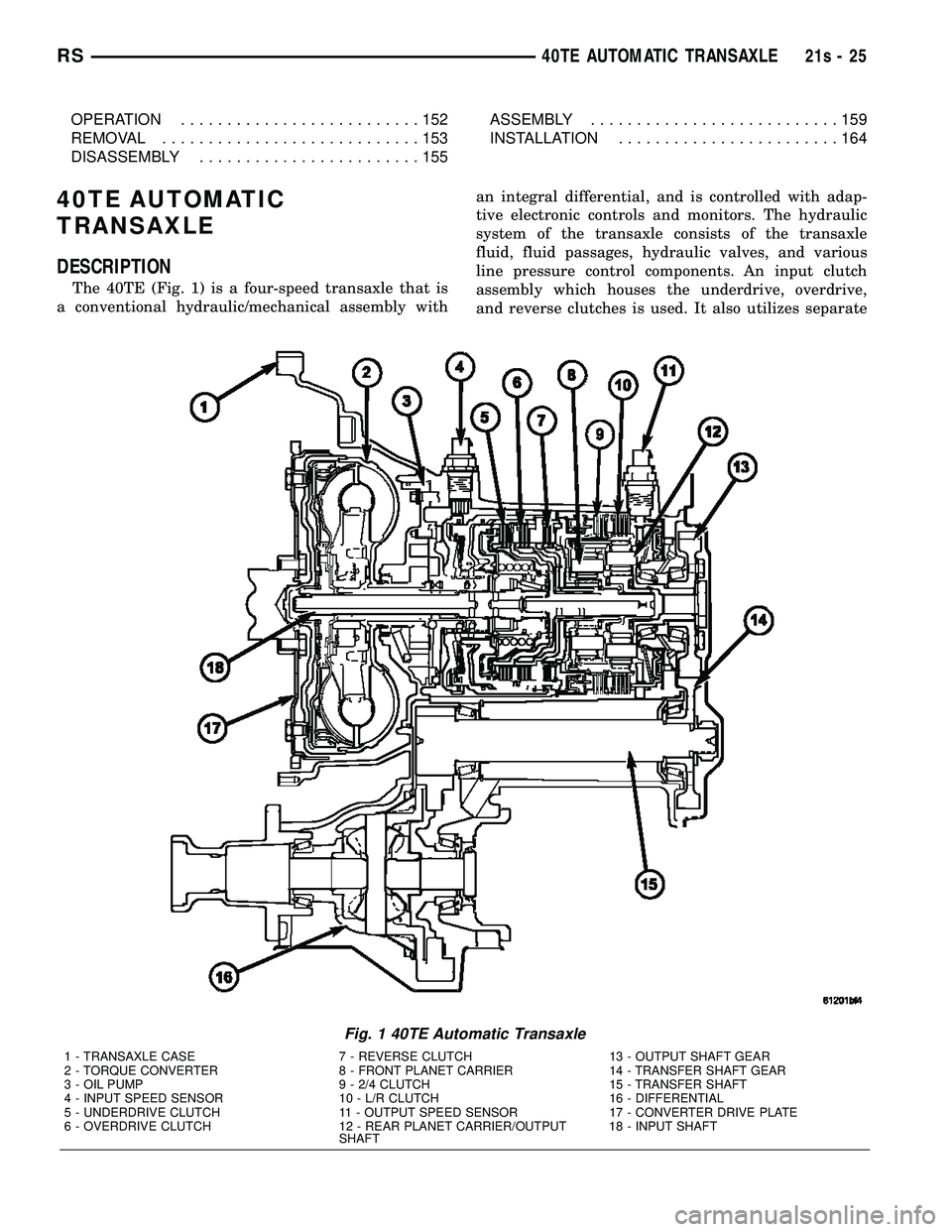
The 40TE (Fig. 1) is a four-speed transaxle that is
a conventional hydraulic/mechanical assembly with an integral differential, and is controlled with adap-
tive electronic controls and monitors. The hydraulic
system of the transaxle consists of the transaxle
fluid, fluid passages, hydraulic valves, and various
line pressure control components. An input clutch
assembly which houses the underdrive, overdrive,
and reverse clutches is used. It also utilizes separate
Fig. 1 40TE Automatic Transaxle
1 - TRANSAXLE CASE 7 - REVERSE CLUTCH 13 - OUTPUT SHAFT GEAR
2 - TORQUE CONVERTER 8 - FRONT PLANET CARRIER 14 - TRANSFER SHAFT GEAR
3 - OIL PUMP 9 - 2/4 CLUTCH 15 - TRANSFER SHAFT
4 - INPUT SPEED SENSOR 10 - L/R CLUTCH 16 - DIFFERENTIAL
5 - UNDERDRIVE CLUTCH 11 - OUTPUT SPEED SENSOR 17 - CONVERTER DRIVE PLATE
6 - OVERDRIVE CLUTCH 12 - REAR PLANET CARRIER/OUTPUT
SHAFT18 - INPUT SHAFT
RS
40TE AUTOMATIC TRANSAXLE21s-25
Page 1887 of 2585
holding clutches: 2nd/4th gear and Low/Reverse. The
primary mechanical components of the transaxle con-
sist of the following:² Three multiple disc input clutches
² Two multiple disc holding clutches
² Four hydraulic accumulators
² Two planetary gear sets
² Hydraulic oil pump
² Valve body
² Solenoid/Pressure switch assembly
² Integral differential assembly
Control of the transaxle is accomplished by fully
adaptive electronics. Optimum shift scheduling is
accomplished through continuous real-time sensor
feedback information provided to the Powertrain
Control Module (PCM) or Transmission Control Mod-
ule (TCM). The PCM/TCM is the heart of the electronic control
system and relies on information from various direct
and indirect inputs (sensors, switches, etc.) to deter-
mine driver demand and vehicle operating condi-
tions. With this information, the PCM/TCM can
calculate and perform timely and quality shifts
through various output or control devices (solenoid
pack, transmission control relay, etc.). The PCM/TCM also performs certain self-diagnos-
tic functions and provides comprehensive information
(sensor data, DTC's, etc.) which is helpful in proper
diagnosis and repair. This information can be viewed
with the DRB scan tool.
TRANSAXLE IDENTIFICATION
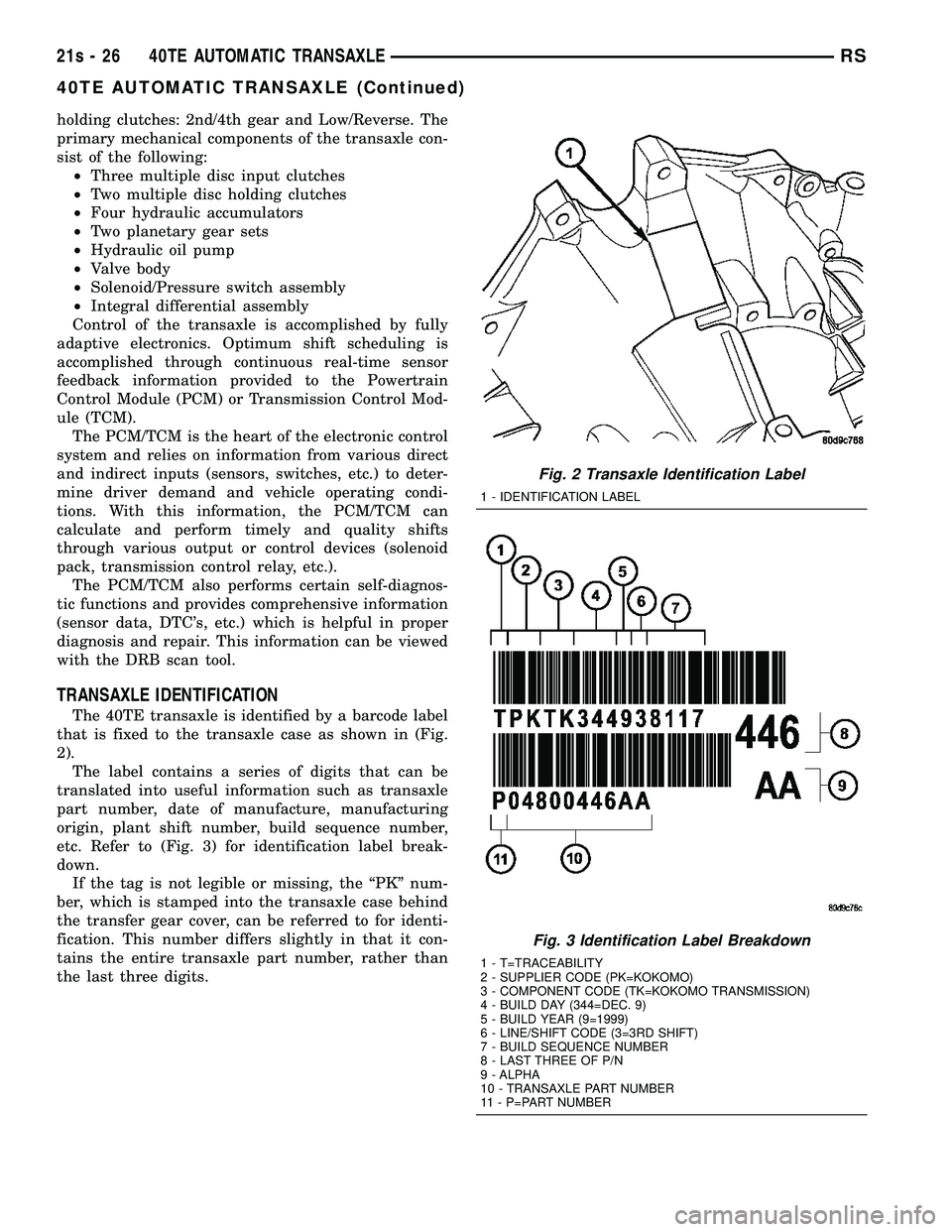
The 40TE transaxle is identified by a barcode label
that is fixed to the transaxle case as shown in (Fig.
2). The label contains a series of digits that can be
translated into useful information such as transaxle
part number, date of manufacture, manufacturing
origin, plant shift number, build sequence number,
etc. Refer to (Fig. 3) for identification label break-
down. If the tag is not legible or missing, the ªPKº num-
ber, which is stamped into the transaxle case behind
the transfer gear cover, can be referred to for identi-
fication. This number differs slightly in that it con-
tains the entire transaxle part number, rather than
the last three digits.
Fig. 2 Transaxle Identification Label
1 - IDENTIFICATION LABEL
Fig. 3 Identification Label Breakdown
1 - T=TRACEABILITY
2 - SUPPLIER CODE (PK=KOKOMO)
3 - COMPONENT CODE (TK=KOKOMO TRANSMISSION)
4 - BUILD DAY (344=DEC. 9)
5 - BUILD YEAR (9=1999)
6 - LINE/SHIFT CODE (3=3RD SHIFT)
7 - BUILD SEQUENCE NUMBER
8 - LAST THREE OF P/N
9 - ALPHA
10 - TRANSAXLE PART NUMBER
11 - P=PART NUMBER
21s - 26 40TE AUTOMATIC TRANSAXLERS
40TE AUTOMATIC TRANSAXLE (Continued)
Page 1891 of 2585
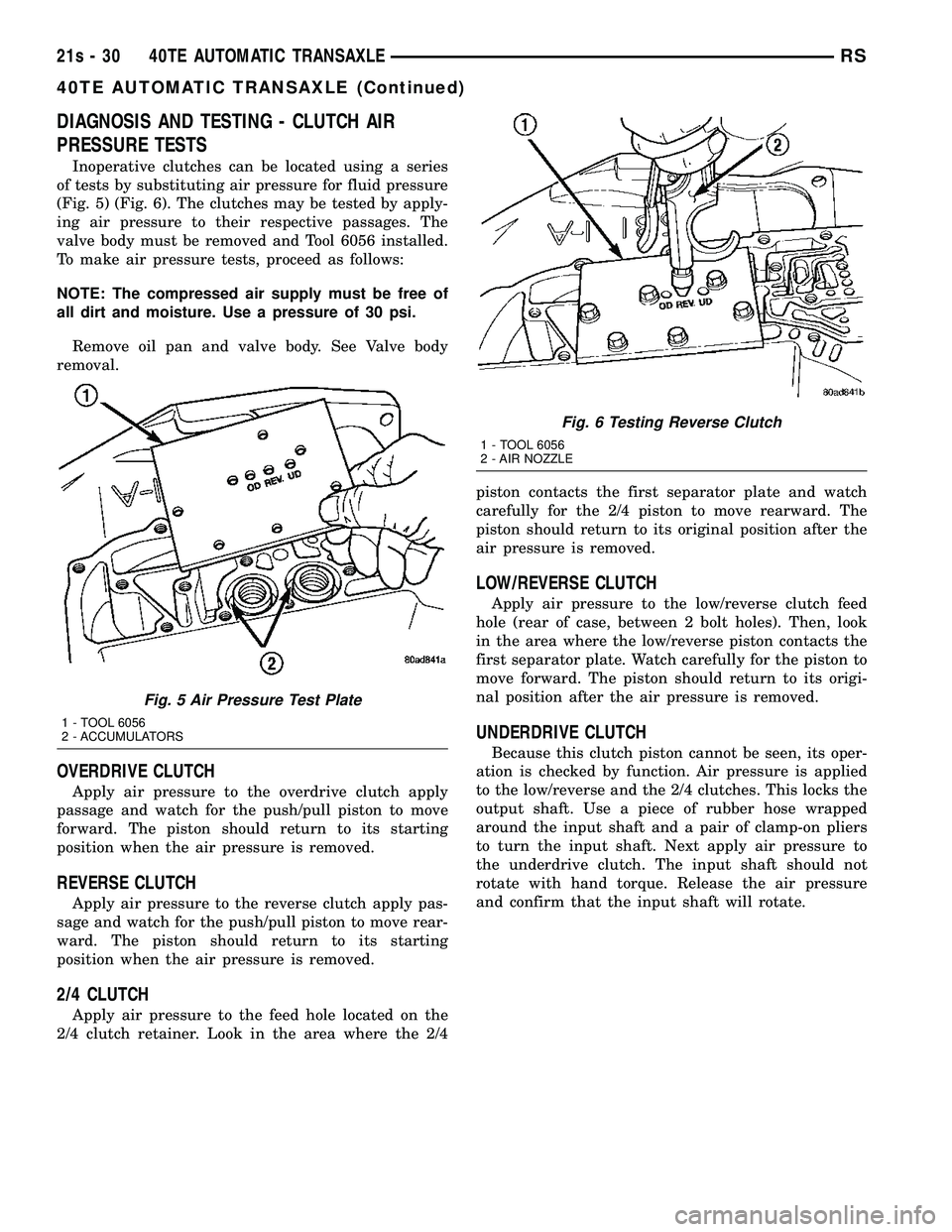
DIAGNOSIS AND TESTING - CLUTCH AIR
PRESSURE TESTS
Inoperative clutches can be located using a series
of tests by substituting air pressure for fluid pressure
(Fig. 5) (Fig. 6). The clutches may be tested by apply-
ing air pressure to their respective passages. The
valve body must be removed and Tool 6056 installed.
To make air pressure tests, proceed as follows:
NOTE: The compressed air supply must be free of
all dirt and moisture. Use a pressure of 30 psi.
Remove oil pan and valve body. See Valve body
removal.
OVERDRIVE CLUTCH
Apply air pressure to the overdrive clutch apply
passage and watch for the push/pull piston to move
forward. The piston should return to its starting
position when the air pressure is removed.
REVERSE CLUTCH
Apply air pressure to the reverse clutch apply pas-
sage and watch for the push/pull piston to move rear-
ward. The piston should return to its starting
position when the air pressure is removed.
2/4 CLUTCH
Apply air pressure to the feed hole located on the
2/4 clutch retainer. Look in the area where the 2/4 piston contacts the first separator plate and watch
carefully for the 2/4 piston to move rearward. The
piston should return to its original position after the
air pressure is removed.
LOW/REVERSE CLUTCH
Apply air pressure to the low/reverse clutch feed
hole (rear of case, between 2 bolt holes). Then, look
in the area where the low/reverse piston contacts the
first separator plate. Watch carefully for the piston to
move forward. The piston should return to its origi-
nal position after the air pressure is removed.
UNDERDRIVE CLUTCH
Because this clutch piston cannot be seen, its oper-
ation is checked by function. Air pressure is applied
to the low/reverse and the 2/4 clutches. This locks the
output shaft. Use a piece of rubber hose wrapped
around the input shaft and a pair of clamp-on pliers
to turn the input shaft. Next apply air pressure to
the underdrive clutch. The input shaft should not
rotate with hand torque. Release the air pressure
and confirm that the input shaft will rotate.
Fig. 5 Air Pressure Test Plate
1 - TOOL 6056
2 - ACCUMULATORS
Fig. 6 Testing Reverse Clutch
1 - TOOL 6056
2 - AIR NOZZLE
21s - 30 40TE AUTOMATIC TRANSAXLERS
40TE AUTOMATIC TRANSAXLE (Continued)
Page 1893 of 2585
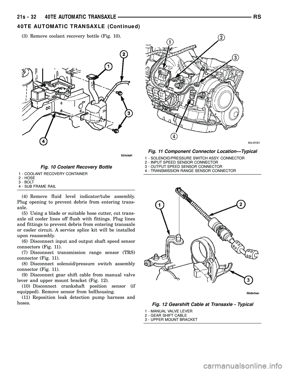
(3) Remove coolant recovery bottle (Fig. 10).
(4) Remove fluid level indicator/tube assembly.
Plug opening to prevent debris from entering trans-
axle. (5) Using a blade or suitable hose cutter, cut trans-
axle oil cooler lines off flush with fittings. Plug lines
and fittings to prevent debris from entering transaxle
or cooler circuit. A service splice kit will be installed
upon reassembly. (6) Disconnect input and output shaft speed sensor
connectors (Fig. 11). (7) Disconnect transmission range sensor (TRS)
connector (Fig. 11). (8) Disconnect solenoid/pressure switch assembly
connector (Fig. 11). (9) Disconnect gear shift cable from manual valve
lever and upper mount bracket (Fig. 12). (10) Disconnect crankshaft position sensor (if
equipped). Remove sensor from bellhousing. (11) Reposition leak detection pump harness and
hoses.
Fig. 10 Coolant Recovery Bottle
1 - COOLANT RECOVERY CONTAINER
2 - HOSE
3 - BOLT
4 - SUB FRAME RAIL
Fig. 11 Component Connector LocationÐTypical
1 - SOLENOID/PRESSURE SWITCH ASSY. CONNECTOR
2 - INPUT SPEED SENSOR CONNECTOR
3 - OUTPUT SPEED SENSOR CONNECTOR
4 - TRANSMISSION RANGE SENSOR CONNECTOR
Fig. 12 Gearshift Cable at Transaxle - Typical
1 - MANUAL VALVE LEVER
2 - GEAR SHIFT CABLE
3 - UPPER MOUNT BRACKET
21s - 32 40TE AUTOMATIC TRANSAXLERS
40TE AUTOMATIC TRANSAXLE (Continued)
Page 1895 of 2585
(27) Lower engine/transaxle assembly with screw
jack. (28) Obtain helper and/or transmission jack.
Secure transmission jack to transaxle assembly. (29) Remove upper mount bracket from transaxle
(Fig. 14). (30) Remove remaining transaxle bellhousing-to-
engine bolts. (31) Remove transaxle assembly from vehicle.
DISASSEMBLY
NOTE: If transaxle is being overhauled (clutch
and/or seal replacement) or replaced, it is neces-
sary to perform the PCM/TCM Quick Learn Proce-
dure. (Refer t o 8 - ELECTRICAL/ELECTRONIC
CONTROL MODULES/POWERTRAIN/TRANSMIS-
SION CONTROL MODULE - STANDARD PROCE-
DURE)
NOTE: This procedure does not include final drive
(differential) disassembly.
(1) Remove input and output speed sensors.
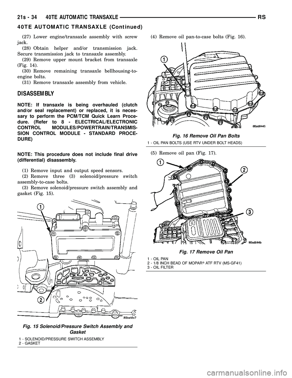
(2) Remove three (3) solenoid/pressure switch
assembly-to-case bolts. (3) Remove solenoid/pressure switch assembly and
gasket (Fig. 15). (4) Remove oil pan-to-case bolts (Fig. 16).
(5) Remove oil pan (Fig. 17).
Fig. 15 Solenoid/Pressure Switch Assembly and
Gasket
1 - SOLENOID/PRESSURE SWITCH ASSEMBLY
2 - GASKET
Fig. 16 Remove Oil Pan Bolts
1 - OIL PAN BOLTS (USE RTV UNDER BOLT HEADS)
Fig. 17 Remove Oil Pan
1 - OIL PAN
2 - 1/8 INCH BEAD OF MOPAR TATF RTV (MS-GF41)
3 - OIL FILTER
21s - 34 40TE AUTOMATIC TRANSAXLERS
40TE AUTOMATIC TRANSAXLE (Continued)
Page 1933 of 2585
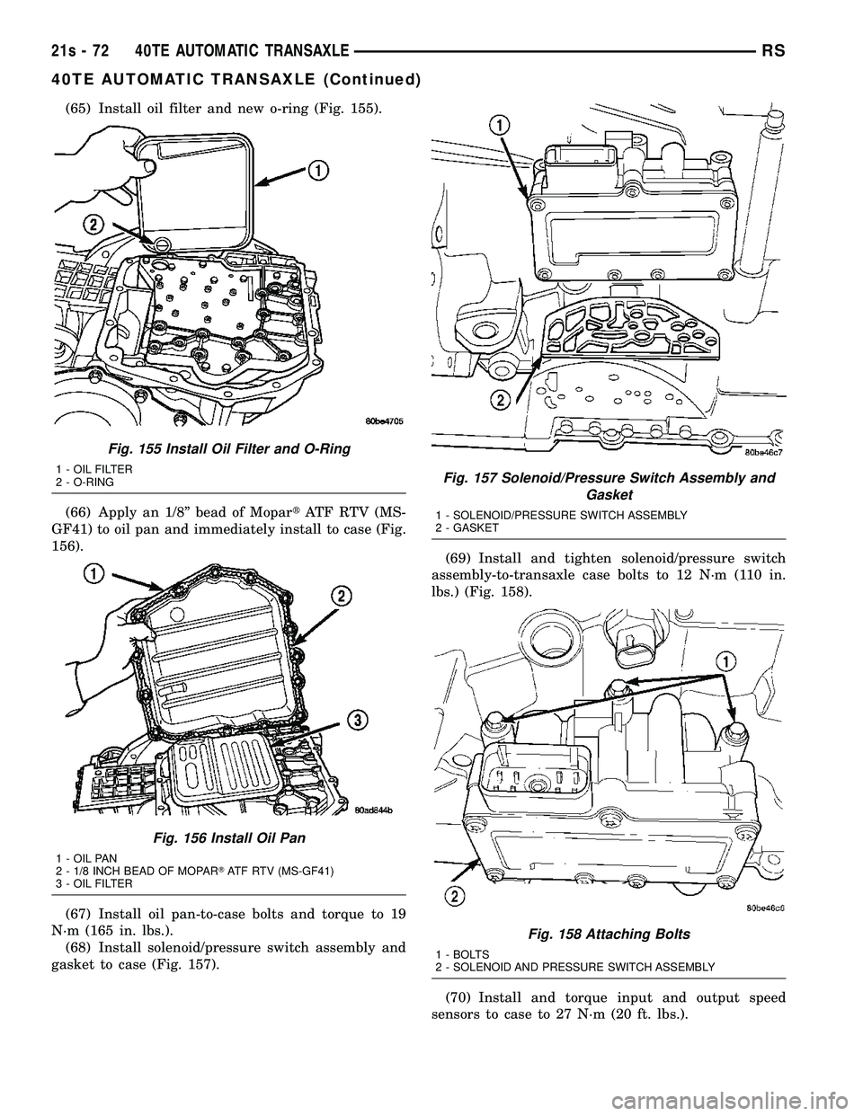
(65) Install oil filter and new o-ring (Fig. 155).
(66) Apply an 1/8º bead of MopartATF RTV (MS-
GF41) to oil pan and immediately install to case (Fig.
156).
(67) Install oil pan-to-case bolts and torque to 19
N´m (165 in. lbs.). (68) Install solenoid/pressure switch assembly and
gasket to case (Fig. 157). (69) Install and tighten solenoid/pressure switch
assembly-to-transaxle case bolts to 12 N´m (110 in.
lbs.) (Fig. 158).
(70) Install and torque input and output speed
sensors to case to 27 N´m (20 ft. lbs.).
Fig. 155 Install Oil Filter and O-Ring
1 - OIL FILTER
2 - O-RING
Fig. 156 Install Oil Pan
1 - OIL PAN
2 - 1/8 INCH BEAD OF MOPAR TATF RTV (MS-GF41)
3 - OIL FILTER
Fig. 157 Solenoid/Pressure Switch Assembly and
Gasket
1 - SOLENOID/PRESSURE SWITCH ASSEMBLY
2 - GASKET
Fig. 158 Attaching Bolts
1 - BOLTS
2 - SOLENOID AND PRESSURE SWITCH ASSEMBLY
21s - 72 40TE AUTOMATIC TRANSAXLERS
40TE AUTOMATIC TRANSAXLE (Continued)