2004 CHRYSLER VOYAGER oil pressure
[x] Cancel search: oil pressurePage 2478 of 2585
(8) Lubricate new rubber O-ring seals with clean
refrigerant oil and install them on the front liquid
line rear section and suction line fittings for the
expansion valve.
(9) Connect the liquid line and suction line fittings
to the expansion valve.
(10) Install the nut that secures the suction line
and liquid line fittings to the stud on the expansion
valve. Tighten the nut to 23 N´m (17 ft. lbs.).
(11) Remove the tape or plugs from the liquid line
rear section fitting and the receiver/drier outlet port.
(12) Lubricate a new rubber O-ring seal with clean
refrigerant oil and install it on the liquid line fitting.
(13) Connect the liquid line fitting to the receiver/
drier outlet port.
(14) Install the screw that secures the liquid line
fitting to the receiver/drier. Tighten the screw to 11
N´m (97 in. lbs.).
(15) Connect the wire harness connector to the A/C
pressure transducer.
(16) Connect the drain tube to the wiper module
drain on the right side of the engine compartment.
(17) Install the air cleaner housing.
(18) Reconnect the battery negative cable.
(19) Evacuate the refrigerant system (Refer to 24 -
HEATING & AIR CONDITIONING/PLUMBING -
FRONT/REFRIGERANT - STANDARD PROCE-
DURE - REFRIGERANT SYSTEM EVACUATE).
(20) Charge the refrigerant system (Refer to 24 -
HEATING & AIR CONDITIONING/PLUMBING -
FRONT/REFRIGERANT - STANDARD PROCE-
DURE - REFRIGERANT SYSTEM CHARGE).
HEATER CORE
DESCRIPTION
The heater core is located in the distribution hous-
ing, which is attached to the HVAC housing, behind
the instrument panel. It is a heat exchanger made of
rows of tubes and fins. One end of the core is fitted
with a molded plastic tank, which includes integral
heater core inlet and outlet ports. Removable heater
core tubes attach to the ports by use of a sealing
plate secured with a screw to the heater core tank.
This removable heater core tube arrangement allows
the heater core to be serviced without removing the
HVAC housing from the vehicle.
OPERATION
Engine coolant is circulated through heater hoses
to the heater core at all times. As the coolant flows
through the heater core, heat removed from the
engine is transferred to the heater core fins and
tubes. Air directed through the heater core picks up
the heat from the heater core fins. The blend doorallows control of the heater output air temperature
by regulating the amount of air that is flowing
through the heater core within the HVAC housing.
The heater core cannot be repaired and, if faulty or
damaged, it must be replaced.
REMOVAL
REMOVAL - HEATER CORE TUBES
WARNING: ON VEHICLES EQUIPPED WITH AIR-
BAGS, DISABLE THE AIRBAG SYSTEM BEFORE
ATTEMPTING ANY STEERING WHEEL, STEERING
COLUMN, OR INSTRUMENT PANEL COMPONENT
DIAGNOSIS OR SERVICE. DISCONNECT AND ISO-
LATE THE BATTERY NEGATIVE (GROUND) CABLE,
THEN WAIT TWO MINUTES FOR THE AIRBAG SYS-
TEM CAPACITOR TO DISCHARGE BEFORE PER-
FORMING FURTHER DIAGNOSIS OR SERVICE. THIS
IS THE ONLY SURE WAY TO DISABLE THE AIRBAG
SYSTEM. FAILURE TO TAKE THE PROPER PRE-
CAUTIONS COULD RESULT IN ACCIDENTAL AIR-
BAG DEPLOYMENT AND POSSIBLE PERSONAL
INJURY.
(1) Drain the engine cooling system (Refer to 7 -
COOLING - STANDARD PROCEDURE - COOLING
SYSTEM DRAIN).
(2) Disconnect and isolate the battery negative
cable.
(3) Disconnect the heater hoses from the heater
core tubes (Refer to 24 - HEATING & AIR CONDI-
TIONING/PLUMBING/HEATER INLET HOSE -
REMOVAL) and (Refer to 24 - HEATING & AIR
CONDITIONING/PLUMBING/HEATER RETURN
HOSE - REMOVAL).
(4) Remove the silencer from beneath the driver
side end of the instrument panel.
NOTE: Take the proper precautions to protect the
carpeting below the heater core from spilled engine
coolant and have absorbent toweling readily avail-
able to clean up any spills.
(5) Remove the screw that secures the heater core
tube sealing plate to the heater core supply and
return ports (Fig. 14).
(6) Push both heater core tubes simultaneously
toward the dash panel far enough to disengage their
fittings from the heater core supply and return ports.
(7) Install plugs in, or tape over the opened heater
core tube fittings and both heater core ports.
(8) Pull both heater core tubes simultaneously
slightly away from the distribution housing and rear-
ward far enough to disengage the engine compart-
ment ends of the tubes from the dash panel seal.
RSPLUMBING - FRONT24-83
EXPANSION VALVE (Continued)
Page 2480 of 2585
INSTALLATION
INSTALLATION - HEATER CORE TUBES
(1) Remove the plugs or tape from both heater core
tube fittings and both heater core ports.
(2) Position the heater core tubes and sealing plate
as a unit beneath the instrument panel.
(3) Align the engine compartment ends of both
heater core tubes with the openings in the dash
panel seal and push them simultaneously forward
through the seal far enough to engage the heater
core ends of the tubes with the heater core supply
and return ports.
(4) Position both heater core tubes and the sealing
plate simultaneously to the heater core supply and
return ports.
NOTE: The heater core tubes each have a slot that
must be indexed to a location tab within each of the
heater core ports. Adjust the position of the tubes
as required so that the sealing plate fits flush
against the heater core supply and return ports,
which indicates that the tubes are properly indexed.
(5) Index both heater core tubes to the heater core
ports.
(6) Install the screw that secures the heater core
tube sealing plate to the heater core supply and
return ports. Tighten the screw to 3 N´m (27 in. lbs.).
(7) Install the silencer under the driver side end of
the instrument panel.
(8) Connect the heater hoses to the heater hose
tubes (Refer to 24 - HEATING & AIR CONDITION-
ING/PLUMBING/HEATER INLET HOSE - INSTAL-
LATION) and(Refer to 24 - HEATING & AIR
CONDITIONING/PLUMBING/HEATER RETURN
HOSE - INSTALLATION).
(9) Reconnect the battery negative cable.
(10) Refill the engine cooling system (Refer to 7 -
COOLING - STANDARD PROCEDURE - COOLING
SYSTEM REFILL).
INSTALLATION - HEATER CORE
(1) While pushing the brake pedal downward and
pulling the accelerator pedal upward far enough for
clearance, slide the heater core into the distribution
housing.
(2) Install the two screws that secure the heater
core mounting plate to the distribution housing.
Tighten the screws to 2 N´m (17 in. lbs.).
(3) Install the heater core tubes (Refer to 24 -
HEATING & AIR CONDITIONING/PLUMBING/
HEATER CORE - INSTALLATION).
(4) Reconnect the power brake booster input rod
(push rod) to the pin on the brake pedal arm (Referto 5 - BRAKES/HYDRAULIC/MECHANICAL/
POWER BRAKE BOOSTER - INSTALLATION).
(5) Reinstall the brake lamp switch into its mount-
ing bracket (Refer to 8 - ELECTRICAL/LAMPS/
LIGHTING - EXTERIOR/BRAKE LAMP SWITCH -
INSTALLATION).
(6) Reinstall the silencer boot around the base of
the lower steering shaft on the dash panel.
(7) Reconnect the battery negative cable.
(8) Refill the engine cooling system (Refer to 7 -
COOLING - STANDARD PROCEDURE - COOLING
SYSTEM REFILL).
(9) Operate system for two thermostat cycles to
assure the elimination of any air that may be
trapped within the cooling system.
HEATER INLET HOSE
REMOVAL
WARNING: REFER TO THE APPLICABLE WARN-
INGS AND CAUTIONS FOR THIS SYSTEM BEFORE
PERFORMING THE FOLLOWING OPERATION (Refer
to 24 - HEATING & AIR CONDITIONING/PLUMBING -
WARNING).
NOTE: The heater inlet hose is constructed from
formed steel tubing and rubber hoses. Depending
on application, the ends are secured to the heater
core, engine oil cooler or the engine by spring ten-
sion clamps.
(1) Drain the engine cooling system (Refer to 7 -
COOLING - STANDARD PROCEDURE - COOLING
SYSTEM DRAIN).
(2) Using spring tension clamp pliers, compress
and slide the clamps off of each end of the hose being
removed (Fig. 17), (Fig. 18) or (Fig. 19).
CAUTION:
DO NOT apply excessive pressure on heater tubes
or connections when removing heater hoses.
Excessive pressure may damage or deform the
tubes/heater core, causing an engine coolant leak.
(3) Disconnect each hose end by carefully twisting
the hose back and forth on the tube or nipple, while
gently pulling it away from the end of the tube or
nipple.
NOTE:
Replacement of the heater inlet hoses will be
required if the hose ends are cut for removal.
(4) If necessary, carefully cut the hose end and
peel the hose off of the tube or nipple.
RSPLUMBING - FRONT24-85
HEATER CORE (Continued)
Page 2485 of 2585
(22) Install plugs in, or tape over the opened liquid
line fittings.
(23) Lower the vehicle.
(24) Remove the front liquid line rear section from
the engine compartment.
INSTALLATION
FRONT SECTION
(1) Position the front section of the front liquid
line into the engine compartment.
(2) Remove the tape or plugs from the liquid line
front section fitting for the receiver/drier and the
receiver/drier inlet port.
(3) Lubricate a new rubber O-ring seal with clean
refrigerant oil and install it on the liquid line fitting.
(4) Reconnect the liquid line fitting to the receiver/
drier inlet port on the top of the receiver/drier.
(5) Install the bolt that secures the liquid line fit-
ting to the receiver/drier. Tighten the bolt to 11 N´m
(97 in. lbs.).
(6) Engage the retainer that secures the liquid line
routing clip to the top of the right frame rail ahead of
the front strut tower in the engine compartment.
(7) Remove the tape or plugs from the A/C con-
denser outlet port and the liquid line fitting.
(8) Lubricate a new rubber O-ring seal with clean
refrigerant oil and install it on the liquid line fitting.
(9) Install a new dual plane seal and reconnect the
liquid line fitting to the condenser outlet port on the
right side of the cooling module.
(10) Install the nut that secures the liquid line fit-
ting to the condenser. Tighten the nut to 23 N´m (17
ft. lbs.).
(11) Position the radiator sight shield onto the
radiator closure panel crossmember.
(12) Install the five small screws that secure the
front fascia grille inserts to the radiator sight shield.
Tighten the screws to 2 N´m (17 in. lbs.).
(13) Install the two large screws that secure the
front fascia and the outboard ends of the radiator
sight shield to the radiator closure panel crossmem-
ber. Tighten the screws to 6 N´m (53 in. lbs.).
(14) Reinstall the air cleaner housing into the
right side of the engine compartment.
(15) Reconnect the battery negative cable.
(16) Evacuate the refrigerant system (Refer to 24 -
HEATING & AIR CONDITIONING/PLUMBING -
FRONT/REFRIGERANT - STANDARD PROCE-
DURE - REFRIGERANT SYSTEM EVACUATE).
(17) Charge the refrigerant system (Refer to 24 -
HEATING & AIR CONDITIONING/PLUMBING -
FRONT/REFRIGERANT - STANDARD PROCE-
DURE - REFRIGERANT SYSTEM CHARGE).REAR SECTION
(1) Position the rear section of the front liquid line
into the engine compartment.
(2) Remove the tape or plugs from the suction line
and liquid line fittings and both expansion valve
ports.
(3) Lubricate new rubber O-ring seals with clean
refrigerant oil and install them on the suction line
and liquid line fittings.
(4) Reconnect the liquid line and suction line fit-
tings to the expansion valve.
(5) Install the nut that secures the suction line
and liquid line fittings to the expansion valve.
Tighten the nut to 23 N´m (17 ft. lbs.).
(6) Remove the tape or plugs from the liquid line
rear section fitting for the receiver/drier and the
receiver/drier outlet port.
(7) Lubricate a new rubber O-ring seal with clean
refrigerant oil and install it on the liquid line fitting.
(8) Reconnect the liquid line fitting to the receiver/
drier outlet port on the top of the receiver/drier.
(9) Install the bolt that secures the liquid line fit-
ting to the receiver/drier. Tighten the bolt to 11 N´m
(97 in. lbs.).
(10) If equipped, reinstall the A/C ground strap
eyelet terminal connector onto the weld stud on the
top of the right front strut tower (if equipped).
(11) If equipped, install the nut that secures the
A/C ground strap to the weld stud. Tighten the nut
to 12 N´m (106 in. lbs.)
(12) Install the A/C pressure transducer (Refer to
24 - HEATING & AIR CONDITIONING/CONTROLS
- FRONT/A/C PRESSURE TRANSDUCER - INSTAL-
LATION).
(13) Reconnect the drain tube to the wiper module
drain on the right side of the engine compartment.
(14) Reinstall the air cleaner housing into the
right side of the engine compartment.
(15) On RHD models, install the liquid line into
the retaining bracket located at the top of the dash
panel.
(16) If the vehicle is equipped with the optional
rear air conditioner, go to Step 17. If the vehicle does
not have the optional rear air conditioner, go to Step
23.
(17) Raise and support the vehicle.
(18) Remove the tape or plugs from the liquid line
rear section extension fitting and the underbody liq-
uid line fitting.
(19) Lubricate a new rubber O-ring seal with clean
refrigerant oil and install it on the underbody liquid
line fitting.
(20) Reconnect the liquid line rear section exten-
sion fitting to the underbody liquid line fitting.
Tighten the fittings to 23 N´m (17 ft. lbs.).
24 - 90 PLUMBING - FRONTRS
LIQUID LINE (Continued)
Page 2492 of 2585
PLUMBING - REAR
TABLE OF CONTENTS
page page
A/C EVAPORATOR
DESCRIPTION.........................97
OPERATION...........................97
REMOVAL
REMOVAL - REAR A/C EVAPORATOR......97
REMOVAL - A/C EVAPORATOR LINE
EXTENSION.........................98
INSTALLATION
INSTALLATION - REAR A/C EVAPORATOR . . 99
INSTALLATION - REAR A/C EVAPORATOR
LINE EXTENSION.....................99
A/C EXPANSION VALVE
DESCRIPTION.........................99
OPERATION...........................99
DIAGNOSIS AND TESTING - EXPANSION
VALVE .............................100
REMOVAL............................100
INSTALLATION........................100
HEATER CORE
DESCRIPTION........................101
OPERATION..........................101
STANDARD PROCEDURE - REAR HEATER
CORE FILLING......................101REMOVAL............................102
INSTALLATION........................103
HEATER HOSES
REMOVAL............................103
INSTALLATION........................104
LIQUID LINE
REMOVAL............................104
INSTALLATION........................105
SUCTION LINE
REMOVAL............................106
INSTALLATION........................107
UNDERBODY LINES
DESCRIPTION........................107
OPERATION..........................107
REMOVAL
REMOVAL - UNDERBODY HEATER TUBES . 109
REMOVAL - UNDERBODY REFRIGERANT
LINES.............................110
INSTALLATION
INSTALLATION - REAR HEATER LINES....111
INSTALLATION - UNDERBODY
REFRIGERANT LINES.................111
A/C EVAPORATOR
DESCRIPTION
The rear A/C evaporator is located in the rear
HVAC housing, behind the right rear wheel house.
The evaporator is positioned in the rear housing so
that all air that enters the housing must pass over
the fins of the evaporator coils before it is distributed
through the system ducts and outlets. However, air
passing over the evaporator fins will only be condi-
tioned when the compressor is engaged and circulat-
ing refrigerant through the evaporator tubes. The
rear HVAC housing must be removed from the vehi-
cle to access the A/C evaporator for service.
OPERATION
Refrigerant enters the rear evaporator from the
rear expansion valve as a low-temperature, low-pres-
sure liquid. As air flows over the fins of the evapora-
tor, the humidity in the air condenses on the fins,
and the heat from the air is absorbed by the refrig-
erant. Heat absorption causes the refrigerant to boil
and vaporize. The refrigerant becomes a low-pressure
gas when it leaves the evaporator.
REMOVAL
REMOVAL - REAR A/C EVAPORATOR
WARNING: REFER TO THE APPLICABLE WARN-
INGS AND CAUTIONS FOR THIS SYSTEM BEFORE
PERFORMING THE FOLLOWING OPERATION (Refer
to 24 - HEATING & AIR CONDITIONING/PLUMBING -
FRONT - WARNING - A/C PLUMBING), (Refer to 24 -
HEATING & AIR CONDITIONING/PLUMBING -
FRONT - CAUTION - A/C PLUMBING), and (Refer to
24 - HEATING & AIR CONDITIONING/PLUMBING -
FRONT - WARNING - HEATER PLUMBING).
(1) Remove the rear HVAC housing from the vehi-
cle (Refer to 24 - HEATING & AIR CONDITIONING/
DISTRIBUTION/HVAC HOUSING - REMOVAL).
(2) Remove the rear evaporator line extension from
the expansion valve (Refer to 24 - HEATING & AIR
CONDITIONING/PLUMBING - REAR/EVAPORA-
TOR - REMOVAL - EVAPORATOR LINE EXTEN-
SION).
(3) Remove the rear expansion valve from the rear
evaporator (Refer to 24 - HEATING & AIR CONDI-
RSPLUMBING - REAR24-97
Page 2494 of 2585
(8) Remove the nut that secures the evaporator
line extension seal plate to the expansion valve stud.
(9) Remove the evaporator line extension seal
plate from the expansion valve stud.
(10) Remove the evaporator line extension from
the expansion valve and the rear HVAC housing
base.
(11) Remove the seals from the evaporator line
extension fittings and discard.
(12) Install plugs in, or tape over the opened evap-
orator line extension fittings and both expansion
valve ports.
INSTALLATION
INSTALLATION - REAR A/C EVAPORATOR
NOTE: If the rear A/C evaporator is being replaced,
add 50 milliliters (1.8 fluid ounces) of refrigerant oil
to the refrigerant system. Use only refrigerant oil of
the type recommended for the compressor in the
vehicle.
(1) Carefully lower the rear A/C evaporator and its
foam wrap into the lower half of the rear HVAC
housing.
(2) Position the upper half of the rear HVAC hous-
ing onto the lower half.
(3) Install the three metal spring clips that secure
the upper half of the rear HVAC housing to the lower
half.
(4) Install the three screws that secure the upper
half of the rear HVAC housing to the lower half.
Tighten the screws to 2 N´m (17 in. lbs.).
(5) Install the rubber grommet that seals the evap-
orator inlet and outlet tubes to the rear HVAC hous-
ing near the expansion valve.
(6) Reinstall the rear expansion valve onto the
rear A/C evaporator (Refer to 24 - HEATING & AIR
CONDITIONING/PLUMBING - REAR/EXPANSION
VALVE - INSTALLATION).
(7) Reinstall the rear evaporator extension line
onto the expansion valve (Refer to 24 - HEATING &
AIR CONDITIONING/PLUMBING - REAR/EVAPO-
RATOR - INSTALLATION - EVAPORATOR EXTEN-
SION LINE).
(8) Reinstall the rear HVAC housing into the vehi-
cle (Refer to 24 - HEATING & AIR CONDITIONING/
DISTRIBUTION - REAR/REAR HEATER-A/C
HOUSING - INSTALLATION).
INSTALLATION - REAR A/C EVAPORATOR LINE
EXTENSION
(1) Remove the tape or plugs from the evaporator
line extension fittings and both expansion valve
ports.(2) Lubricate new rubber O-ring seals with clean
refrigerant oil and install them on the evaporator
line extension fittings.
(3) Position the evaporator line extension to the
expansion valve and the rear HVAC housing base.
(4) Position the evaporator line extension seal
plate over the expansion valve stud.
(5) Install the nut that secures the evaporator line
extension seal plate to the expansion valve stud.
Tighten the nut to 23 N´m (17 ft. lbs.).
(6) Position the expansion valve bracket over the
expansion valve stud.
(7) Install the two screws that secure the expan-
sion valve bracket to the lower rear HVAC housing.
Tighten the screws to 2 N´m (17 in. lbs.).
(8) Install the nut that secures the expansion
valve bracket to the expansion valve stud. Tighten
the nut to 23 N´m (17 ft. lbs.).
(9) Carefully restore the expansion valve foam
insulator wrap back around the expansion valve.
(10) Position the plate that captures and seals the
evaporator line extension onto the rear HVAC hous-
ing base.
(11) Install the screw that secures the capture
plate to the base of the rear HVAC housing. Tighten
the screw to 2 N´m (17 in. lbs.).
(12) Install the rear HVAC housing into the vehi-
cle (Refer to 24 - HEATING & AIR CONDITIONING/
DISTRIBUTION/HVAC HOUSING -
INSTALLATION).
A/C EXPANSION VALVE
DESCRIPTION
The rear ªHº valve-type thermal expansion valve
(TXV) is located at the rear of the rear HVAC hous-
ing between the evaporator line extension and the
evaporator coil. High-pressure, low temperature liq-
uid refrigerant from the liquid line passes through
the expansion valve orifice, converting it into a low-
pressure, low-temperature mixture of liquid and gas
before it enters the evaporator coil.
OPERATION
A mechanical sensor in the expansion valve control
head monitors the temperature and pressure of the
refrigerant leaving the evaporator coil through the
suction line, and adjusts the orifice size at the liquid
line to let the proper amount of refrigerant into the
evaporator coil to meet the vehicle cooling require-
ments. Controlling the refrigerant flow through the
evaporator ensures that none of the refrigerant leav-
ing the evaporator is still in a liquid state, which
could damage the compressor.
RSPLUMBING - REAR24-99
A/C EVAPORATOR (Continued)
Page 2495 of 2585
The rear A/C expansion valve cannot be adjusted
or repaired and, if faulty or damaged, it must be
replaced.
DIAGNOSIS AND TESTING - EXPANSION VALVE
WARNING: REFER TO THE APPLICABLE WARN-
INGS AND CAUTIONS FOR THIS SYSTEM BEFORE
PERFORMING THE FOLLOWING OPERATION.
(Refer to 24 - HEATING & AIR CONDITIONING/
PLUMBING - FRONT - WARNING - A/C PLUMBING)
and (Refer to 24 - HEATING & AIR CONDITIONING/
PLUMBING - FRONT - CAUTION - A/C PLUMBING).
NOTE: The expansion valve should only be tested
following testing of the compressor.
NOTE: Liquid CO
2is required to test the expansion
valve. This material is available from most welding
supply facilities. Liquid CO
2is also available from
companies which service and sell fire extinguish-
ers.
When testing the expansion valve, the work area
and the vehicle temperature must be 21É to 27É C
(70É to 85É F). To test the expansion valve:
(1) Connect a charging station or manifold gauge
set to the refrigerant system service ports. Verify the
refrigerant charge level.
(2) Close all doors, windows and vents to the pas-
senger compartment.
(3) Set the heater-air conditioner controls so that
the compressor is operating, the temperature control
is in the highest temperature position, the mode door
is directing the output to the floor outlets, and the
blower is operating at the highest speed setting.
(4) Start the engine and allow it to idle at 1000
rpm. After the engine has reached normal operating
temperature, allow the passenger compartment to
heat up. This will create the need for maximum
refrigerant flow into the evaporator.
(5) If the refrigerant charge is sufficient, the dis-
charge (high pressure) gauge should read 965 to 1655
kPa (140 to 240 psi). The suction (low pressure)
gauge should read 140 kPa to 207 kPa (20 psi to 30
psi). If OK, go to Step 6. If not OK, replace the faulty
expansion valve.
WARNING: PROTECT THE SKIN AND EYES FROM
EXPOSURE TO LIQUID CO
2. PERSONAL INJURY
CAN RESULT.
(6) If the suction (low pressure) gauge reads
within the specified range, freeze the expansion valve
control head for 30 seconds using liquid CO
2or
another suitable super-cold material.Do not sprayR-134a or R-12 refrigerant on the expansion
valve control head for this test.The suction (low
pressure) gauge reading should drop by 10 psi. If OK,
go to Step 7 If not OK, replace the faulty expansion
valve.
(7) Allow the expansion valve control head to thaw.
The suction (low pressure) gauge reading should sta-
bilize at 140 kPa to 240 kPa (20 psi to 30 psi). If not
OK, replace the faulty expansion valve.
(8) When expansion valve testing is complete, test
the overall air conditioner performance (Refer to 24 -
HEATING & AIR CONDITIONING - DIAGNOSIS
AND TESTING - A/C PERFORMANCE TEST).
Remove all test equipment before returning the vehi-
cle to service.
REMOVAL
WARNING: REFER TO THE APPLICABLE WARN-
INGS AND CAUTIONS FOR THIS SYSTEM BEFORE
PERFORMING THE FOLLOWING OPERATION (Refer
to 24 - HEATING & AIR CONDITIONING/PLUMBING -
FRONT - WARNING - A/C PLUMBING), (Refer to 24 -
HEATING & AIR CONDITIONING/PLUMBING -
FRONT - CAUTION - A/C PLUMBING), and (Refer to
24 - HEATING & AIR CONDITIONING/PLUMBING -
FRONT - WARNING - HEATER PLUMBING).
(1) Remove the rear HVAC housing from the vehi-
cle (Refer to 24 - HEATING & AIR CONDITIONING/
DISTRIBUTION/HVAC HOUSING - REMOVAL).
(2) Carefully remove the foam insulator wrap from
the rear expansion valve.
(3) Remove the rear evaporator line extension from
the expansion valve (Refer to 24 - HEATING & AIR
CONDITIONING/PLUMBING - REAR/EVAPORA-
TOR - REMOVAL - EVAPORATOR LINE EXTEN-
SION).
(4) Remove the two screws that secure the expan-
sion valve to the evaporator tube sealing plate.
(5) Remove the expansion valve from the evapora-
tor tubes.
(6) Remove the seals from the evaporator tube fit-
tings and discard.
(7) Install plugs in, or tape over the opened evap-
orator tube fittings and both expansion valve ports.
INSTALLATION
(1) Remove the tape or plugs from the rear A/C
evaporator tube fittings and both expansion valve
ports.
(2) Lubricate new rubber O-ring seals with clean
refrigerant oil and install them on the rear evapora-
tor tube fittings.
(3) Position the expansion valve onto the evapora-
tor tubes.
24 - 100 PLUMBING - REARRS
A/C EXPANSION VALVE (Continued)
Page 2500 of 2585
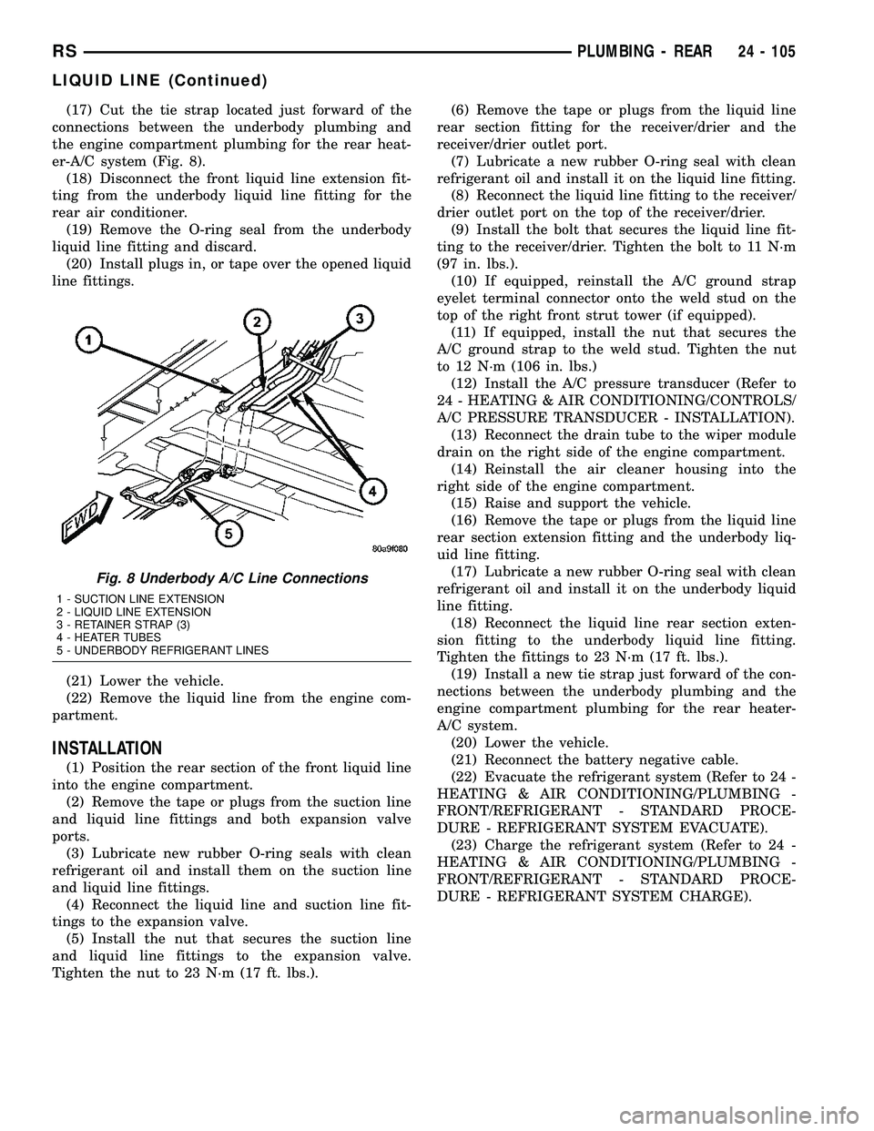
(17) Cut the tie strap located just forward of the
connections between the underbody plumbing and
the engine compartment plumbing for the rear heat-
er-A/C system (Fig. 8).
(18) Disconnect the front liquid line extension fit-
ting from the underbody liquid line fitting for the
rear air conditioner.
(19) Remove the O-ring seal from the underbody
liquid line fitting and discard.
(20) Install plugs in, or tape over the opened liquid
line fittings.
(21) Lower the vehicle.
(22) Remove the liquid line from the engine com-
partment.
INSTALLATION
(1) Position the rear section of the front liquid line
into the engine compartment.
(2) Remove the tape or plugs from the suction line
and liquid line fittings and both expansion valve
ports.
(3) Lubricate new rubber O-ring seals with clean
refrigerant oil and install them on the suction line
and liquid line fittings.
(4) Reconnect the liquid line and suction line fit-
tings to the expansion valve.
(5) Install the nut that secures the suction line
and liquid line fittings to the expansion valve.
Tighten the nut to 23 N´m (17 ft. lbs.).(6) Remove the tape or plugs from the liquid line
rear section fitting for the receiver/drier and the
receiver/drier outlet port.
(7) Lubricate a new rubber O-ring seal with clean
refrigerant oil and install it on the liquid line fitting.
(8) Reconnect the liquid line fitting to the receiver/
drier outlet port on the top of the receiver/drier.
(9) Install the bolt that secures the liquid line fit-
ting to the receiver/drier. Tighten the bolt to 11 N´m
(97 in. lbs.).
(10) If equipped, reinstall the A/C ground strap
eyelet terminal connector onto the weld stud on the
top of the right front strut tower (if equipped).
(11) If equipped, install the nut that secures the
A/C ground strap to the weld stud. Tighten the nut
to 12 N´m (106 in. lbs.)
(12) Install the A/C pressure transducer (Refer to
24 - HEATING & AIR CONDITIONING/CONTROLS/
A/C PRESSURE TRANSDUCER - INSTALLATION).
(13) Reconnect the drain tube to the wiper module
drain on the right side of the engine compartment.
(14) Reinstall the air cleaner housing into the
right side of the engine compartment.
(15) Raise and support the vehicle.
(16) Remove the tape or plugs from the liquid line
rear section extension fitting and the underbody liq-
uid line fitting.
(17) Lubricate a new rubber O-ring seal with clean
refrigerant oil and install it on the underbody liquid
line fitting.
(18) Reconnect the liquid line rear section exten-
sion fitting to the underbody liquid line fitting.
Tighten the fittings to 23 N´m (17 ft. lbs.).
(19) Install a new tie strap just forward of the con-
nections between the underbody plumbing and the
engine compartment plumbing for the rear heater-
A/C system.
(20) Lower the vehicle.
(21) Reconnect the battery negative cable.
(22) Evacuate the refrigerant system (Refer to 24 -
HEATING & AIR CONDITIONING/PLUMBING -
FRONT/REFRIGERANT - STANDARD PROCE-
DURE - REFRIGERANT SYSTEM EVACUATE).
(23) Charge the refrigerant system (Refer to 24 -
HEATING & AIR CONDITIONING/PLUMBING -
FRONT/REFRIGERANT - STANDARD PROCE-
DURE - REFRIGERANT SYSTEM CHARGE).
Fig. 8 Underbody A/C Line Connections
1 - SUCTION LINE EXTENSION
2 - LIQUID LINE EXTENSION
3 - RETAINER STRAP (3)
4 - HEATER TUBES
5 - UNDERBODY REFRIGERANT LINES
RSPLUMBING - REAR24 - 105
LIQUID LINE (Continued)
Page 2502 of 2585
(18) Install plugs in, or tape over the opened suc-
tion line fittings.
(19) Lower the vehicle.
(20) Remove the suction line from the engine com-
partment.
INSTALLATION
(1) Position the suction line into the engine com-
partment.
(2) Remove the tape or plugs from the suction line
and liquid line fittings and both expansion valve
ports.
(3) Lubricate new rubber O-ring seals with clean
refrigerant oil and install them on the suction line
and liquid line fittings.
(4) Reconnect the liquid line and suction line fit-
tings to the expansion valve.
(5) Install the nut that secures the suction line
and liquid line fittings to the front expansion valve.
Tighten the nut to 23 N´m (17 ft. lbs.).
(6) Engage the retainer that secures the suction
line routing clip to the receiver/drier mounting
bracket on the side of the right front strut tower in
the engine compartment.
(7) Remove the tape or plugs from the compressor
suction port and the suction line fitting.
(8) Lubricate a new rubber O-ring seal with clean
refrigerant oil and install it on the suction line fit-
ting.
(9) Reconnect the suction line fitting to the com-
pressor suction port.
(10) Install the nut that secures the suction line
fitting to the A/C compressor. Tighten the nut to 23
N´m (17 ft. lbs.).
(11) Reconnect the drain tube to the wiper module
drain on the right side of the engine compartment.
(12) Reinstall the air cleaner top cover and snorkel
onto the air cleaner housing located on the right side
of the engine compartment.
(13) Reconnect the battery negative cable.
(14) Raise and support the vehicle.
(15) Remove the tape or plugs from the suction
line extension fitting and the underbody suction line
fitting.(16) Lubricate a new rubber O-ring seal with clean
refrigerant oil and install it on the underbody suction
line fitting.
(17) Reconnect the suction line extension fitting to
the underbody suction line fitting. Tighten the fitting
to 23 N´m (17 ft. lbs.).
(18) Install a new tie strap just forward of the con-
nections between the underbody plumbing and the
engine compartment plumbing for the rear heater
and air conditioner.
(19) Lower the vehicle.
(20) Evacuate the refrigerant system (Refer to 24 -
HEATING & AIR CONDITIONING/PLUMBING -
FRONT/REFRIGERANT - STANDARD PROCE-
DURE - REFRIGERANT SYSTEM EVACUATE).
(21) Charge the refrigerant system (Refer to 24 -
HEATING & AIR CONDITIONING/PLUMBING -
FRONT/REFRIGERANT - STANDARD PROCE-
DURE - REFRIGERANT SYSTEM CHARGE).
UNDERBODY LINES
DESCRIPTION
The underbody heater-A/C plumbing is used only
on models with the optional rear heater-A/C system
(Fig. 11). The underbody suction line, liquid line, and
heater tubes can each be serviced separately.
OPERATION
The rear heater and A/C lines are all serviced as
individual pieces. When disconnecting any line or
block ensure that the area around it is clean of any
contaminations that can get in to the system (Fig.
12), (Fig. 13), (Fig. 15), (Fig. 14) and (Fig. 16).
Any kinks or sharp bends in the rear heater-A/C
unit plumbing will reduce the capacity of the entire
heating and air conditioning system. Kinks and
sharp bends reduce the system flow. High pressures
are produced in the refrigerant system when the air
conditioning compressor is operating. High tempera-
ture coolant is present in the heater plumbing when
the engine is operating. Extreme care must be exer-
cised o make sure that each of the plumbing connec-
tions is pressure-tight and leak free.
RSPLUMBING - REAR24 - 107
SUCTION LINE (Continued)