2004 CHRYSLER VOYAGER cooling
[x] Cancel search: coolingPage 2455 of 2585
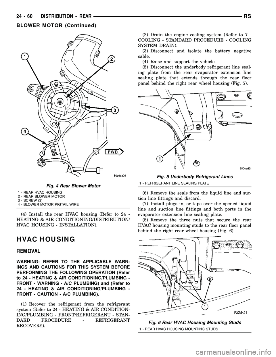
(4) Install the rear HVAC housing (Refer to 24 -
HEATING & AIR CONDITIONING/DISTRIBUTION/
HVAC HOUSING - INSTALLATION).
HVAC HOUSING
REMOVAL
WARNING: REFER TO THE APPLICABLE WARN-
INGS AND CAUTIONS FOR THIS SYSTEM BEFORE
PERFORMING THE FOLLOWING OPERATION (Refer
to 24 - HEATING & AIR CONDITIONING/PLUMBING -
FRONT - WARNING - A/C PLUMBING) and (Refer to
24 - HEATING & AIR CONDITIONING/PLUMBING -
FRONT - CAUTION - A/C PLUMBING).
(1) Recover the refrigerant from the refrigerant
system (Refer to 24 - HEATING & AIR CONDITION-
ING/PLUMBING - FRONT/REFRIGERANT - STAN-
DARD PROCEDURE - REFRIGERANT
RECOVERY).(2) Drain the engine cooling system (Refer to 7 -
COOLING - STANDARD PROCEDURE - COOLING
SYSTEM DRAIN).
(3) Disconnect and isolate the battery negative
cable.
(4) Raise and support the vehicle.
(5) Disconnect the underbody refrigerant line seal-
ing plate from the rear evaporator extension line
sealing plate that extends through the rear floor
panel behind the right rear wheel housing (Fig. 5).
(6) Remove the seals from the liquid line and suc-
tion line fittings and discard.
(7) Install plugs in, or tape over the opened liquid
line and suction line fittings and both ports in the
evaporator extension line sealing plate.
(8) Remove the three nuts that secure the rear
HVAC housing mounting studs to the rear floor panel
behind the right rear wheel housing (Fig. 6).
Fig. 4 Rear Blower Motor
1 - REAR HVAC HOUSING
2 - REAR BLOWER MOTOR
3 - SCREW (3)
4 - BLOWER MOTOR PIGTAIL WIRE
Fig. 5 Underbody Refrigerant Lines
1 - REFRIGERANT LINE SEALING PLATE
Fig. 6 Rear HVAC Housing Mounting Studs
1 - REAR HVAC HOUSING MOUNTING STUDS
24 - 60 DISTRIBUTION - REARRS
BLOWER MOTOR (Continued)
Page 2457 of 2585
(16) Lubricate new rubber O-ring seals with clean
refrigerant oil and install them on the liquid line and
suction line fittings.
(17) Reconnect the underbody refrigerant line seal-
ing plate to the evaporator extension line sealing
plate.
(18) Install the screw that secures the underbody
refrigerant line sealing plate to the evaporator exten-
sion line sealing plate. Tighten the screw to 23 N´m
(17 ft. lbs.).
(19) Lower the vehicle.
(20) Reconnect the battery negative cable.
(21) Refill the engine cooling system (Refer to 7 -
COOLING - STANDARD PROCEDURE - COOLING
SYSTEM REFILL).
(22) Evacuate the refrigerant system (Refer to 24 -
HEATING & AIR CONDITIONING/PLUMBING -
FRONT/REFRIGERANT - STANDARD PROCE-
DURE - REFRIGERANT SYSTEM EVACUATE).
(23) Charge the refrigerant system (Refer to 24 -
HEATING & AIR CONDITIONING/PLUMBING -FRONT/REFRIGERANT - STANDARD PROCE-
DURE - REFRIGERANT SYSTEM CHARGE).
(24) Run the HVAC Cooldown test to verify proper
operation (Refer to 24 - HEATING & AIR CONDI-
TIONING - DIAGNOSIS AND TESTING).
REAR FLOOR HEAT DUCT
REMOVAL
(1) Remove the trim from the right quarter inner
panel (Refer to 23 - BODY/INTERIOR/RIGHT
QUARTER TRIM PANEL - REMOVAL).
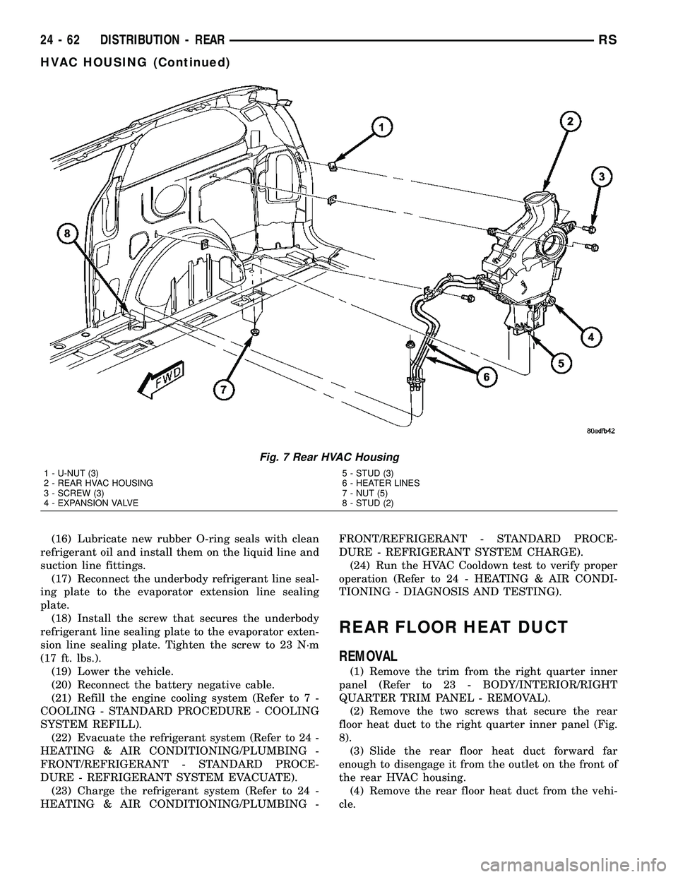
(2) Remove the two screws that secure the rear
floor heat duct to the right quarter inner panel (Fig.
8).
(3) Slide the rear floor heat duct forward far
enough to disengage it from the outlet on the front of
the rear HVAC housing.
(4) Remove the rear floor heat duct from the vehi-
cle.
Fig. 7 Rear HVAC Housing
1 - U-NUT (3)
2 - REAR HVAC HOUSING
3 - SCREW (3)
4 - EXPANSION VALVE5 - STUD (3)
6 - HEATER LINES
7 - NUT (5)
8 - STUD (2)
24 - 62 DISTRIBUTION - REARRS
HVAC HOUSING (Continued)
Page 2459 of 2585
PLUMBING - FRONT
TABLE OF CONTENTS
page page
PLUMBING - FRONT
DESCRIPTION - REFRIGERANT LINE.......65
OPERATION- REFRIGERANT LINES........65
WARNING
ENGINE COOLING SYSTEM.............65
A/C SYSTEM.........................65
CAUTION
A/C SYSTEM.........................66
DIAGNOSIS AND TESTING
DIAGNOSIS AND TESTING - REFRIGERANT
SYSTEM LEAKS......................66
DIAGNOSIS AND TESTING - SYSTEM
CHARGE LEVEL TEST - GASOLINE
ENGINES............................67
DIAGNOSIS AND TESTING - SYSTEM
CHARGE LEVEL TEST - 2.5L DIESEL......68
STANDARD PROCEDURE
STANDARD PROCEDURE - HANDLING
TUBING AND FITTINGS.................70
STANDARD PROCEDURE - REFRIGERANT
SYSTEM SERVICE EQUIPMENT..........70
STANDARD PROCEDURE - REFRIGERANT
RECOVERY..........................71
STANDARD PROCEDURE - REFRIGERANT
SYSTEM EVACUATE...................72
STANDARD PROCEDURE - REFRIGERANT
SYSTEM CHARGE.....................72
A/C COMPRESSOR
DESCRIPTION
DESCRIPTION - A/C COMPRESSOR.......73
DESCRIPTION - HIGH PRESSURE RELIEF
VALVE..............................73
OPERATION
OPERATION - A/C COMPRESSOR........73
OPERATION - HIGH PRESSURE RELIEF
VALVE..............................73
DIAGNOSIS AND TESTING - COMPRESSOR
NOISE DIAGNOSIS....................74
REMOVAL
REMOVAL - COMPRESSOR.............74
REMOVAL - A/C COMPRESSOR MOUNTING
BRACKET - 2.4L ENGINE...............75
INSTALLATION
INSTALLATION.......................76
INSTALLATION - A/C COMPRESSOR
MOUNTING BRACKET - 2.4L ENGINE......76
A/C CONDENSER
DESCRIPTION.........................76
OPERATION...........................76REMOVAL.............................77
INSTALLATION.........................78
A/C DISCHARGE LINE
REMOVAL.............................79
INSTALLATION.........................80
A/C EVAPORATOR
DESCRIPTION.........................80
OPERATION...........................80
REMOVAL.............................80
INSTALLATION.........................80
EXPANSION VALVE
DESCRIPTION.........................81
OPERATION...........................81
DIAGNOSIS AND TESTING - A/C EXPANSION
VALVE ..............................81
REMOVAL.............................82
INSTALLATION.........................82
HEATER CORE
DESCRIPTION.........................83
OPERATION...........................83
REMOVAL
REMOVAL - HEATER CORE TUBES.......83
REMOVAL - HEATER CORE.............84
INSTALLATION
INSTALLATION - HEATER CORE TUBES....85
INSTALLATION - HEATER CORE..........85
HEATER INLET HOSE
REMOVAL.............................85
INSTALLATION.........................86
HEATER RETURN HOSE
REMOVAL.............................86
INSTALLATION.........................87
LIQUID LINE
REMOVAL.............................88
INSTALLATION.........................90
RECEIVER / DRIER
DESCRIPTION.........................91
OPERATION...........................91
REMOVAL.............................91
INSTALLATION.........................92
REFRIGERANT
DESCRIPTION.........................92
OPERATION...........................92
REFRIGERANT OIL
DESCRIPTION.........................92
OPERATION...........................92
STANDARD PROCEDURE - REFRIGERANT
OIL LEVEL...........................93
24 - 64 PLUMBING - FRONTRS
Page 2460 of 2585
SERVICE PORT VALVE CORE
DESCRIPTION.........................94
REMOVAL.............................94
INSTALLATION.........................94SUCTION LINE
REMOVAL.............................94
INSTALLATION.........................95
PLUMBING - FRONT
DESCRIPTION - REFRIGERANT LINE
The refrigerant lines and hoses are used to carry
the refrigerant between the various air conditioning
system components. A barrier hose design with a
nylon tube, which is sandwiched between rubber lay-
ers, is used for the R-134a air conditioning system on
this vehicle. This nylon tube helps to further contain
the R-134a refrigerant, which has a smaller molecu-
lar structure than R-12 refrigerant. The ends of the
refrigerant hoses are made from lightweight alumi-
num or steel, and commonly use braze-less fittings.
Any kinks or sharp bends in the refrigerant plumb-
ing will reduce the capacity of the entire air condi-
tioning system. Kinks and sharp bends reduce the
flow of refrigerant in the system. A good rule for the
flexible hose refrigerant lines is to keep the radius of
all bends at least ten times the diameter of the hose.
In addition, the flexible hose refrigerant lines should
be routed so they are at least 80 millimeters (3
inches) from an exhaust manifold.
OPERATION- REFRIGERANT LINES
High pressures are produced in the refrigerant sys-
tem when the air conditioning compressor is operat-
ing. Extreme care must be exercised to make sure
that each of the refrigerant system connections is
pressure-tight and leak free. It is a good practice to
inspect all flexible hose refrigerant lines at least once
a year to make sure they are in good condition and
properly routed.
The refrigerant lines and hoses are coupled with
other components of the HVAC system with either
O-rings or dual plane seals.
The refrigerant lines and hoses cannot be repaired
and, if faulty or damaged, they must be replaced.
WARNING
ENGINE COOLING SYSTEM
WARNING: THE ENGINE COOLING SYSTEM IS
DESIGNED TO DEVELOP INTERNAL PRESSURES
OF 97 TO 123 KILOPASCALS (14 TO 18 POUNDS
PER SQUARE INCH). DO NOT REMOVE OR
LOOSEN THE COOLANT PRESSURE CAP, CYLIN-
DER BLOCK DRAIN PLUGS, RADIATOR DRAIN,
RADIATOR HOSES, HEATER HOSES, OR HOSE
CLAMPS WHILE THE ENGINE COOLING SYSTEM ISHOT AND UNDER PRESSURE. FAILURE TO
OBSERVE THIS WARNING CAN RESULT IN SERI-
OUS BURNS FROM THE HEATED ENGINE COOL-
ANT. ALLOW THE VEHICLE TO COOL FOR A
MINIMUM OF 15 MINUTES BEFORE OPENING THE
COOLING SYSTEM FOR SERVICE.
A/C SYSTEM
WARNING: THE AIR CONDITIONING SYSTEM CON-
TAINS REFRIGERANT UNDER HIGH PRESSURE.
SEVERE PERSONAL INJURY MAY RESULT FROM
IMPROPER SERVICE PROCEDURES. REPAIRS
SHOULD ONLY BE PERFORMED BY QUALIFIED
SERVICE PERSONNEL.
AVOID BREATHING THE REFRIGERANT AND
REFRIGERANT OIL VAPOR OR MIST. EXPOSURE
MAY IRRITATE THE EYES, NOSE, AND/OR THROAT.
WEAR EYE PROTECTION WHEN SERVICING THE
AIR CONDITIONING REFRIGERANT SYSTEM. SERI-
OUS EYE INJURY CAN RESULT FROM DIRECT
CONTACT WITH THE REFRIGERANT. IF EYE CON-
TACT OCCURS, SEEK MEDICAL ATTENTION IMME-
DIATELY.
DO NOT EXPOSE THE REFRIGERANT TO OPEN
FLAME. POISONOUS GAS IS CREATED WHEN
REFRIGERANT IS BURNED. AN ELECTRONIC LEAK
DETECTOR IS RECOMMENDED.
IF ACCIDENTAL SYSTEM DISCHARGE OCCURS,
VENTILATE THE WORK AREA BEFORE RESUMING
SERVICE. LARGE AMOUNTS OF REFRIGERANT
RELEASED IN A CLOSED WORK AREA WILL DIS-
PLACE THE OXYGEN AND CAUSE SUFFOCATION.
THE EVAPORATION RATE OF R-134a REFRIGER-
ANT AT AVERAGE TEMPERATURE AND ALTITUDE
IS EXTREMELY HIGH. AS A RESULT, ANYTHING
THAT COMES IN CONTACT WITH THE REFRIGER-
ANT WILL FREEZE. ALWAYS PROTECT THE SKIN
OR DELICATE OBJECTS FROM DIRECT CONTACT
WITH THE REFRIGERANT.
THE R-134a SERVICE EQUIPMENT OR THE VEHI-
CLE REFRIGERANT SYSTEM SHOULD NOT BE
PRESSURE TESTED OR LEAK TESTED WITH COM-
PRESSED AIR. SOME MIXTURES OF AIR AND
R-134a HAVE BEEN SHOWN TO BE COMBUSTIBLE
AT ELEVATED PRESSURES. THESE MIXTURES ARE
POTENTIALLY DANGEROUS, AND MAY RESULT IN
FIRE OR EXPLOSION CAUSING INJURY OR PROP-
ERTY DAMAGE.
RSPLUMBING - FRONT24-65
Page 2461 of 2585
CAUTION
A/C SYSTEM
CAUTION: Liquid refrigerant is corrosive to metal
surfaces. Follow the operating instructions supplied
with the service equipment being used.
Never add R-12 to a refrigerant system designed to
use R-134a and do not use R-12 equipment or parts
on the R-134a system. Damage to the system will
result.
R-12 refrigerant oil must not be mixed with R-134a
refrigerant oil. They are not compatible and damage
to the system will result.
Do not overcharge the refrigerant system. Over-
charging will cause excessive compressor head
pressure and can cause noise and system failure.
Recover the refrigerant before opening any fitting
or connection. Open the fittings with caution, even
after the system has been discharged. Never open
or loosen a connection before recovering the refrig-
erant.
If equipped, do not remove the secondary retention
clip from any spring-lock coupler connection while
the refrigerant system is under pressure. Recover
the refrigerant before removing the secondary
retention clip. Open the fittings with caution, even
after the system has been discharged. Never open
or loosen a connection before recovering the refrig-
erant.
Do not open the refrigerant system or uncap a
replacement component until you are ready to ser-
vice the system. This will prevent contamination in
the system. Before disconnecting a component,
clean the outside of the fittings thoroughly to pre-
vent contamination from entering the refrigerant
system. Immediately after disconnecting a compo-
nent from the refrigerant system, seal the open fit-
tings with a cap or plug.
Refrigerant oil will absorb moisture from the atmo-
sphere if left uncapped. Do not open a container of
refrigerant oil until you are ready to use it. Replace
the cap on the oil container immediately after using.
Store refrigerant oil only in a clean, airtight, and
moisture-free container.
Keep service tools and the work area clean. Con-
tamination of the refrigerant system must be
avoided.
CAUTION: The use of A/C system sealers may
result in damage to A/C refrigerant recovery/evacu-
ation/recharging equipment and/or A/C systems.
Many federal, state/provincial and local regulations
prohibit the recharge of A/C systems with known
leaks. DaimlerChrysler recommends the detection
of A/C system leaks through the use of approvedleak detectors and fluorescent leak detection dyes.
Vehicles found with A/C system sealers should be
treated as contaminated and replacement of the
entire A/C refrigerant system is recommended. A/C
systems found to be contaminated with A/C system
sealers, A/C stop-leak products or seal conditioners
voids the warranty for the A/C system.
DIAGNOSIS AND TESTING
DIAGNOSIS AND TESTING - REFRIGERANT
SYSTEM LEAKS
WARNING: R-134a SERVICE EQUIPMENT OR VEHI-
CLE A/C SYSTEM SHOULD NOT BE PRESSURE
TESTED OR LEAK TESTED WITH COMPRESSED
AIR. MIXTURE OF AIR and R-134a CAN BE COM-
BUSTIBLE AT ELEVATED PRESSURES. THESE MIX-
TURES ARE POTENTIALLY DANGEROUS AND MAY
RESULT IN FIRE OR EXPLOSION CAUSING INJURY
OR PROPERTY DAMAGE.
AVOID BREATHING A/C REFRIGERANT AND LUBRI-
CANT VAPOR OR MIST. EXPOSURE MAY IRRITATE
EYES, NOSE AND THROAT. USE ONLY APPROVED
SERVICE EQUIPMENT MEETING SAE REQUIRE-
MENTS TO DISCHARGE R-134a SYSTEM. IF ACCI-
DENTAL SYSTEM DISCHARGE OCCURS,
VENTILATE WORK AREA BEFORE RESUMING SER-
VICE.
If the A/C system is not cooling properly, determine
if the refrigerant system is fully charged with R-134a
(Refer to 24 - HEATING & AIR CONDITIONING/
PLUMBING - FRONT/REFRIGERANT - DIAGNO-
SIS AND TESTING - REFRIGERANT SYSTEM
CHARGE LEVEL). If while performing this test A/C
liquid line pressure is less than 345 kPa (50 psi) pro-
ceed to System Empty procedure. If liquid line pres-
sure is greater than 345 kPa (50 psi) proceed to
System Low procedure. If the refrigerant system is
empty or low in refrigerant charge, a leak at any line
fitting or component seal is likely. A review of the fit-
tings, lines and components for oily residue is an
indication of the leak location.
To detect a leak in the refrigerant system, perform
one of the following procedures as indicated by the
results of the refrigerant system charge level test.
SYSTEM EMPTY
(1) Evacuate the refrigerant system to the lowest
degree of vacuum possible (approx. 28 in Hg.) (Refer
to 24 - HEATING & AIR CONDITIONING/PLUMB-
ING - FRONT/REFRIGERANT - STANDARD PRO-
CEDURE - REFRIGERANT SYSTEM EVACUATE).
Determine if the system holds a vacuum for 15 min-
utes. If vacuum is held, a leak is probably not
24 - 66 PLUMBING - FRONTRS
PLUMBING - FRONT (Continued)
Page 2469 of 2585
The high pressure relief valve is a factory-cali-
brated unit. The valve cannot be adjusted or
repaired, and must not be removed or otherwise dis-
turbed. The valve is only serviced as a part of the
compressor assembly.
DIAGNOSIS AND TESTING - COMPRESSOR
NOISE DIAGNOSIS
Excessive noise while the air conditioning compres-
sor is operating can be caused by loose compressor
mounts, a loose compressor clutch, or high operating
pressures in the refrigerant system. Verify compres-
sor drive belt condition, proper compressor mounting,
correct refrigerant charge level, and compressor head
pressure before compressor repair is performed.
With the close tolerances within the compressor, it
is possible to experience a temporary lockup. The
longer the compressor is inactive, the more likely the
condition is to occur. This condition is the result of
normal refrigerant migration within the refrigerant
system caused by ambient temperature changes. The
refrigerant migration may wash the refrigerant oil
out of the compressor.
NOTE: Prior to a vehicle being removed from ser-
vice or stored for more than two weeks, the com-
pressor should be operated to ensure adequate
refrigerant oil distribution throughout the system
components. Turn on the air conditioner for a min-
imum of five minutes with outside air and the high-
est blower speed selected.
BELT NOISE
If the compressor drive belt slips at initial start-up,
it does not necessarily mean the compressor has
failed. The following procedure can be used to iden-
tify a compressor drive belt noise problem.
A. Start the vehicle and run at idle.
B. Turn the air conditioner On and listen for belt
squeal.
C. If belt squeal is heard, turn the air conditioner
Off immediately.
If the belt squeal stops when the air conditioner is
turned Off, perform the following repair procedures.
(1) Using an appropriate sized oil filter wrench or
a strap wrench, grasp the outer diameter of the com-
pressor clutch hub. While facing the compressor,
rotate the hub clockwise, then counterclockwise. If
the hub rotates, proceed to the next step. If the hub
will not rotate, the compressor is internally damaged,
and must be replaced.
(2) Turn the hub clockwise five complete revolu-
tions and remove the tool.
(3) Start the vehicle and run at idle.(4) Turn the air conditioner On. Observe the com-
pressor and the system for normal operation, noting
cooling performance and noise levels. Operate for five
minutes before turning the air conditioner Off. If
acceptable cooling performance is observed during
compressor operation, the compressor does not need
to be replaced.
(5) Inspect the drive belt for wear, damage, and
proper tension. (Refer to 7 - COOLING/ACCESSORY
DRIVE/DRIVE BELTS - DIAGNOSIS AND TEST-
ING).
REMOVAL
REMOVAL - COMPRESSOR
WARNING: REFER TO THE APPLICABLE WARN-
INGS AND CAUTIONS FOR THIS SYSTEM BEFORE
PERFORMING THE FOLLOWING OPERATION (Refer
to 24 - HEATING & AIR CONDITIONING/PLUMBING -
FRONT - WARNING - A/C PLUMBING) and (Refer to
24 - HEATING & AIR CONDITIONING/PLUMBING -
FRONT - CAUTION - A/C PLUMBING).
(1) Recover the refrigerant from the refrigerant
system (Refer to 24 - HEATING & AIR CONDITION-
ING/PLUMBING - FRONT/REFRIGERANT - STAN-
DARD PROCEDURE - REFRIGERANT
RECOVERY).
(2) Disconnect and isolate the battery negative
cable.
(3) Remove the nut that secures the suction line
fitting to the top of the compressor.
(4) Disconnect the suction line fitting from the
compressor suction port.
(5) Remove the O-ring seal and gasket from the
suction line fitting and discard.
(6) Install plugs in, or tape over the opened suc-
tion line fitting and the compressor suction port.
(7) Remove the nut that secures the discharge line
fitting to the top of the compressor.
(8) Disconnect the discharge line fitting from the
compressor discharge port.
(9) Remove the O-ring seal and gasket from the
discharge line fitting and discard.
(10) Install plugs in, or tape over the opened dis-
charge line fitting and the compressor discharge port.
(11) Raise and support the vehicle.
(12) Remove the serpentine accessory drive belt
from the front of the engine (Refer to 7 - COOLING/
ACCESSORY DRIVE/DRIVE BELTS).
(13) Disconnect the engine wire harness connector
from the compressor clutch coil pigtail wire connector
on the top of the compressor (Fig. 5) or (Fig. 6).
(14) On models with the 3.3L and 3.8L engines,
disengage the retainer on the engine wire harness
24 - 74 PLUMBING - FRONTRS
A/C COMPRESSOR (Continued)
Page 2471 of 2585
INSTALLATION
INSTALLATION
NOTE: If a replacement A/C compressor is being
installed, be certain to check the refrigerant oil level
(Refer to 24 - HEATING & AIR CONDITIONING/
PLUMBING - FRONT/REFRIGERANT OIL - STAN-
DARD PROCEDURE - REFRIGERANT OIL LEVEL).
Use only refrigerant oil of the type recommended
for the compressor in the vehicle.
NOTE: The filter/drier should always be replaced
when the compressor is replaced. This will remove
any contaminants including moisture from the sys-
tem.
(1) Position the A/C compressor into the engine
compartment.
(2) On models with the 2.4L and 2.5L engine,
loosely install the four bolts that secure the compres-
sor to the mounting bracket on the engine (2.4L), or
the cylinder block (2.5L). Tighten the bolts to 28 N´m
(21 ft. lbs.).
(3) On models with the 3.3L and 3.8L engines,
loosely install the two bolts and two nuts that secure
the compressor to the engine. Tighten each of the fas-
teners using the following sequence to 54 N´m (40 ft.
lbs.).
²The upper nut at the front of the compressor.
²The lower nut at the front of the compressor.
²The upper bolt at the rear of the compressor.
²The lower bolt at the rear of the compressor.
(4) On models with the 3.3L and 3.8L engines,
engage the retainer on the engine wire harness com-
pressor clutch coil take out to the bracket on the top
of the compressor.
(5) Connect the engine wire harness connector to
the compressor clutch coil pigtail wire connector on
the top of the compressor.
(6) Reinstall the serpentine accessory drive belt
(Refer to 7 - COOLING/ACCESSORY DRIVE/DRIVE
BELTS).
(7) Lower the vehicle.
(8) Remove the tape or plugs from the compressor
discharge port and the discharge line fitting.
(9) Lubricate a new rubber O-ring seal with clean
refrigerant oil and install it on the discharge line fit-
ting.
(10) Install a new gasket and reconnect the dis-
charge line fitting to the compressor discharge port.
(11) Install the nut that secures the discharge line
fitting to the compressor. Tighten the nut to 23 N´m
(17 ft. lbs.).
(12) Remove the tape or plugs from the compressor
suction port and the suction line fitting.(13) Lubricate a new rubber O-ring seal with clean
refrigerant oil and install it on the suction line fit-
ting.
(14) Install a new gasket and reconnect the suc-
tion line fitting to the compressor suction port.
(15) Install the nut that secures the suction line
fitting to the compressor. Tighten the nut to 23 N´m
(17 ft. lbs.).
(16) Reconnect the battery negative cable.
(17) Evacuate the refrigerant system (Refer to 24 -
HEATING & AIR CONDITIONING/PLUMBING -
FRONT/REFRIGERANT - STANDARD PROCE-
DURE - REFRIGERANT SYSTEM EVACUATE).
(18) Charge the refrigerant system (Refer to 24 -
HEATING & AIR CONDITIONING/PLUMBING -
FRONT/REFRIGERANT - STANDARD PROCE-
DURE - REFRIGERANT SYSTEM CHARGE).
INSTALLATION - A/C COMPRESSOR
MOUNTING BRACKET - 2.4L ENGINE
(1) Position the compressor mounting bracket onto
the engine.
(2) Install the four bolts that secure the compres-
sor mounting bracket to the engine. Tighten the bolts
to 54 N´m (40 ft. lbs.).
(3) Reinstall the A/C compressor onto the mount-
ing bracket (Refer to 24 - HEATING & AIR CONDI-
TIONING/PLUMBING/COMPRESSOR -
INSTALLATION).
A/C CONDENSER
DESCRIPTION
The A/C condenser is integral to a cooling module
which includes the radiator, the electric cooling fan,
the fan shroud, air seals and an automatic transmis-
sion oil cooler. The cooling module is located in the
air flow in the front of the engine compartment
behind the radiator grille. The A/C condenser is a
heat exchanger that allows the high-pressure refrig-
erant gas being discharged from the compressor to
give up its heat to the air passing over the condenser
fins. The A/C condenser may be removed from the
cooling module for service without removing the cool-
ing module from the vehicle.
OPERATION
When the refrigerant gas gives up its heat, it con-
denses. When the refrigerant leaves the condenser, it
has become a high-pressure liquid refrigerant. The
volume of air flowing over the condenser fins is crit-
ical to the proper cooling performance of the air con-
ditioning system. Therefore, it is important that
there are no objects placed in front of the radiator
grille openings in the front of the vehicle or foreign
24 - 76 PLUMBING - FRONTRS
A/C COMPRESSOR (Continued)
Page 2472 of 2585
material on the condenser fins that might obstruct
air flow. Also, any factory-installed air seals or
shrouds must be properly reinstalled following radia-
tor or condenser service.
The A/C condenser cannot be repaired or adjusted,
and if faulty or damaged, it must be replaced.
REMOVAL
WARNING: REFER TO THE APPLICABLE WARN-
INGS AND CAUTIONS FOR THIS SYSTEM BEFORE
PERFORMING THE FOLLOWING OPERATION (Refer
to 24 - HEATING & AIR CONDITIONING/PLUMBING -
FRONT - WARNING - A/C PLUMBING) and (Refer to
24 - HEATING & AIR CONDITIONING/PLUMBING -
FRONT - CAUTION - A/C PLUMBING).
NOTE: Before removing the condenser, note the
location of each of the radiator and condenser air
seals. These air seals are used to direct air through
the condenser and radiator. The air seals must be
reinstalled in their proper locations in order for the
air conditioning and engine cooling systems to per-
form as designed.
(1) Recover the refrigerant from the refrigerant
system (Refer to 24 - HEATING & AIR CONDITION-
ING/PLUMBING - FRONT/REFRIGERANT - STAN-
DARD PROCEDURE - REFRIGERANT
RECOVERY).
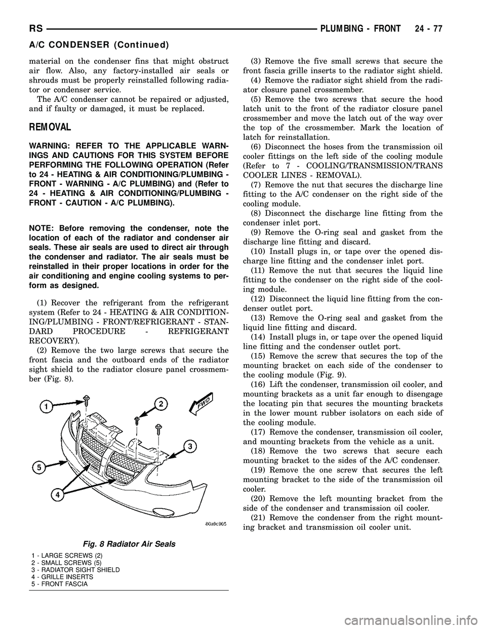
(2) Remove the two large screws that secure the
front fascia and the outboard ends of the radiator
sight shield to the radiator closure panel crossmem-
ber (Fig. 8).(3) Remove the five small screws that secure the
front fascia grille inserts to the radiator sight shield.
(4) Remove the radiator sight shield from the radi-
ator closure panel crossmember.
(5) Remove the two screws that secure the hood
latch unit to the front of the radiator closure panel
crossmember and move the latch out of the way over
the top of the crossmember. Mark the location of
latch for reinstallation.
(6) Disconnect the hoses from the transmission oil
cooler fittings on the left side of the cooling module
(Refer to 7 - COOLING/TRANSMISSION/TRANS
COOLER LINES - REMOVAL).
(7) Remove the nut that secures the discharge line
fitting to the A/C condenser on the right side of the
cooling module.
(8) Disconnect the discharge line fitting from the
condenser inlet port.
(9) Remove the O-ring seal and gasket from the
discharge line fitting and discard.
(10) Install plugs in, or tape over the opened dis-
charge line fitting and the condenser inlet port.
(11) Remove the nut that secures the liquid line
fitting to the condenser on the right side of the cool-
ing module.
(12) Disconnect the liquid line fitting from the con-
denser outlet port.
(13) Remove the O-ring seal and gasket from the
liquid line fitting and discard.
(14) Install plugs in, or tape over the opened liquid
line fitting and the condenser outlet port.
(15) Remove the screw that secures the top of the
mounting bracket on each side of the condenser to
the cooling module (Fig. 9).
(16) Lift the condenser, transmission oil cooler, and
mounting brackets as a unit far enough to disengage
the locating pin that secures the mounting brackets
in the lower mount rubber isolators on each side of
the cooling module.
(17) Remove the condenser, transmission oil cooler,
and mounting brackets from the vehicle as a unit.
(18) Remove the two screws that secure each
mounting bracket to the sides of the A/C condenser.
(19) Remove the one screw that secures the left
mounting bracket to the side of the transmission oil
cooler.
(20) Remove the left mounting bracket from the
side of the condenser and transmission oil cooler.
(21) Remove the condenser from the right mount-
ing bracket and transmission oil cooler unit.
Fig. 8 Radiator Air Seals
1 - LARGE SCREWS (2)
2 - SMALL SCREWS (5)
3 - RADIATOR SIGHT SHIELD
4 - GRILLE INSERTS
5 - FRONT FASCIA
RSPLUMBING - FRONT24-77
A/C CONDENSER (Continued)