Page 49 of 80
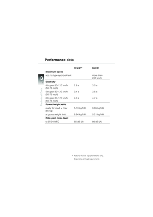
47
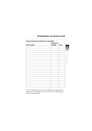
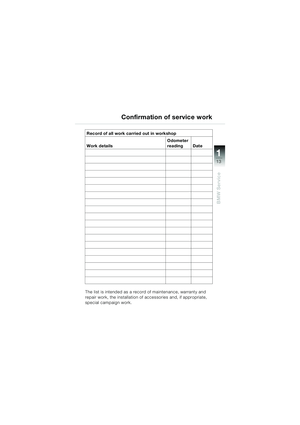
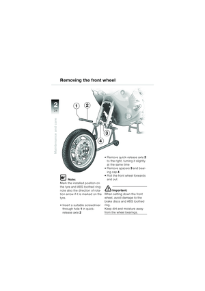
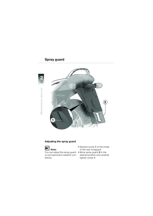
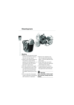
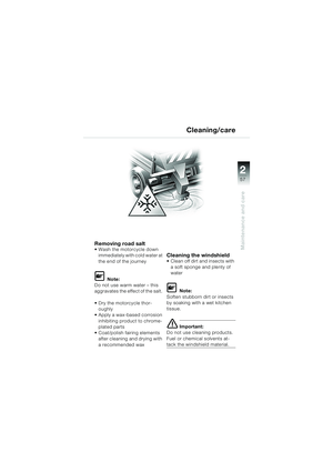
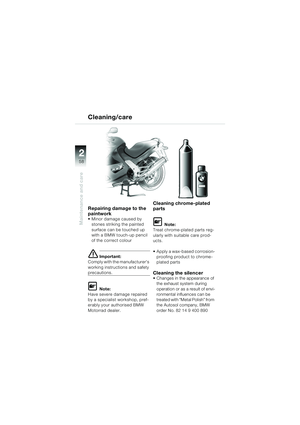
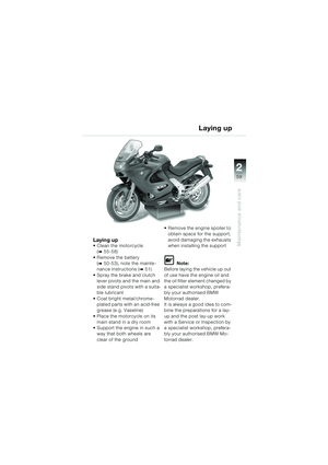
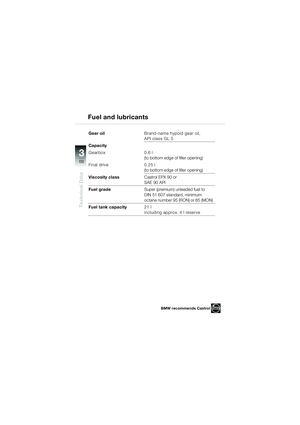
Maintenance and care
2
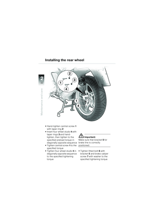
11
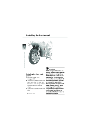
7
6
12
8
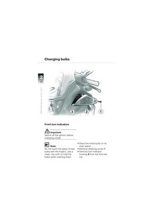
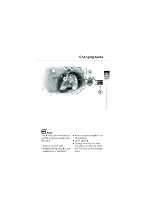
910Changing bulbs
Using a screwdriver, press in
one retaining lug 11 at left and
right, and open up the bulb
holder
Pull the H3 bulb out of bulb
ring 10
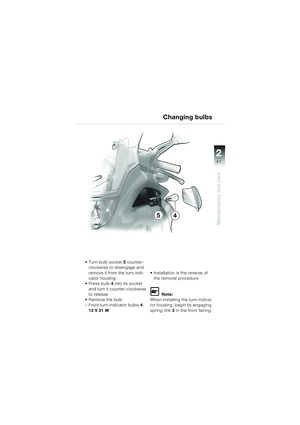
Installation is the reverse of
the removal procedure
– Main beam headlamp:
H3 12 V 55 W
L Note:
When installing
– Make sure that groove 7 (radi-
used) and groove 9 (corners)
are correctly positioned
– Align groove 6 in such a way
that it points toward guide 8
– Make sure that retainers 11
on left and right engage
–Tab 4 to the right
– Note grooves 12 on left and
right and make sure that
ground connector 5 engages
20k41bkg3.book Seite 47 Mittwoch, 26. Mai 2004 3:33 15
Page 50 of 80
48
Maintenance and care
2
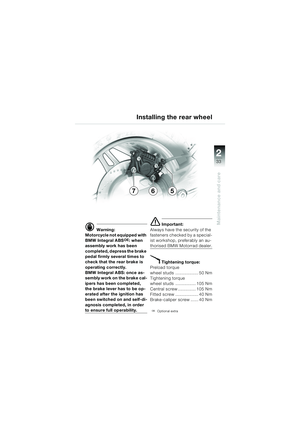
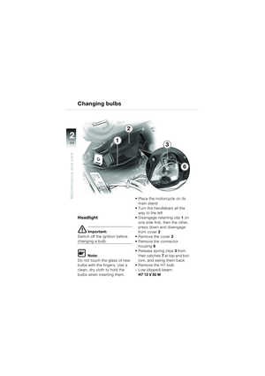
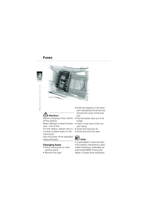
e Attention:
Before changing a fuse, switch
off the ignition.
Never attempt to repair a blown
fuse – risk of fire!
For this reason, always carry a
number of spare fuses on the
motorcycle.
Use only fuses of the specified
rating and type.
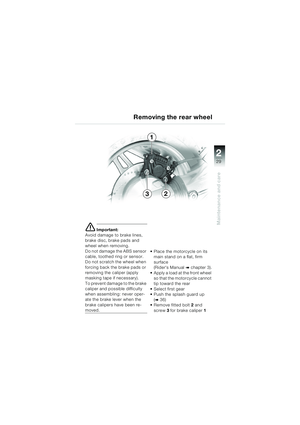
Changing fuses Place motorcycle on main (centre) stand
Remove the seat Push the retainers in the direc-
tion indicated by the arrow and
remove the cover of the fuse
box
Pull the blown fuse out of its
holder
Insert a new fuse of the cor- rect rating
Close the fuse box lid
Close and lock the seat
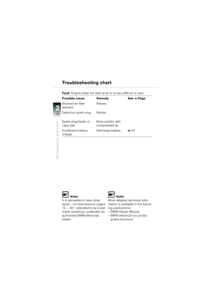
L Note:
It is advisable to have the elec-
trical system checked by a spe-
cialist workshop, preferably an
authorised BMW motorcycle
dealer, if fuses blow frequently.
Fuses
20k41bkg3.book Seite 48 Mittwoch, 26. Mai 2004 3:33 15
Page 51 of 80
49
Maintenance and care
2
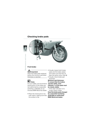
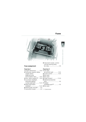
Fuse assignment
Fuse box 1
1 Engine electronics ........ 10 A
2 Fuel pump, injection valves,
oxygen sensor,
diagnosis plug,
tank breather valve ........ 10 A
3 Horn, alarm system
OE... 10 A
4 Low beam headlight,
instrument lighting,
number-plate light ......... 7,5 A
5 High (main) beam
headlight ...................... 7,5 A
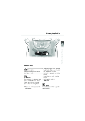
6 Parking light, tail light ..... 4 A
7 Instrument cluster ........... 4 A 8
Instrument cluster, control
unit fuel warning lamp,
fan relay .......................... 4 A
Fuse box 2
1 Fan relay,
fan left and right ........... 10 A
2 Cruise control ............... 10 A
3 Not used
4 Not used
5 Power socket I ............ 7,5 A
6 Optional accessories
plug ............................... 4 A
7 Heated
handlebar grip
OE ............ 4 A
8 Not used
OEOptional extra
Fuses
12
20k41bkg3.book Seite 49 Mittwoch, 26. Mai 2004 3:33 15
Page 52 of 80
 50
Maintenance and care
2
Battery safety instructions
Gel batteries are maintenance-
free. Compliance with the
instructions below is important
in order to maximise battery life:
e Attention:
– Kee")
50
Maintenance and care
2
Battery safety instructions
Gel batteries are maintenance-
free. Compliance with the
instructions below is important
in order to maximise battery life:
e Attention:
– Keep the surface of the battery clean and dry
– Do not attempt to open the battery
– Do not attempt to top up the battery with water
– Use only electronically
controlled battery chargers
with a limit voltage of 14.4 V to
charge the battery.
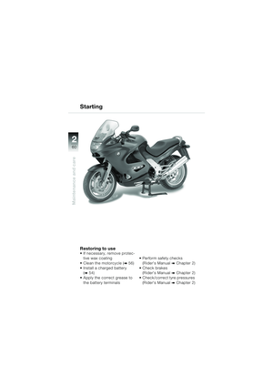
Correct upkeep, recharging
and storage will prolong the life
of the battery and are essential
if warranty claims are to be con-
sidered.
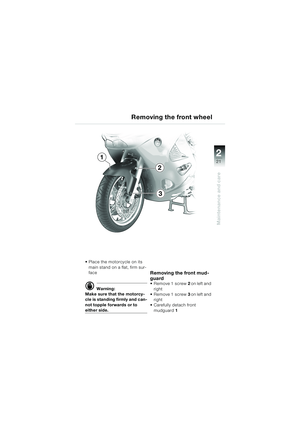
d Warning:
Do not attempt to jump-start
the motorcycle using the on-
board socket
–Risk of fire!
Push-start the motorcycle only when the engine is
cold.
The load capacity of the
electrical wiring to the power
socket is not sufficient to start
the motorcycle from an outside
source.
e Attention:
Do not attempt to jump-start
the motorcycle if the battery is
completely flat: recharge the
battery instead.
Risk of damaging the control
units.
20k41bkg3.book Seite 50 Mittwoch, 26. Mai 2004 3:33 15
Page 53 of 80
 51
Maintenance and care
2
Battery maintenance instructions
Motorcycle out of use for a
lengthy period
The battery has to be charged prior to lay-up periods of
more than one month.
e Attention:
If")
51
Maintenance and care
2
Battery maintenance instructions
Motorcycle out of use for a
lengthy period
The battery has to be charged prior to lay-up periods of
more than one month.
e Attention:
If the battery is not
disconnected, the on-board
electronics (clock, etc.) will
discharge the battery. This can
cause the battery to run flat. If
this happens, warranty claims
will not be accepted.
Disconnect the ground (earth)
lead from the battery prior to a
lay-up. – Batteries that are not in use
must be stored in a cool
place. Do not store a
discharged battery
– If the battery is in storage for an extended period of time,
recharge it at regular intervals
of approx. 4 months. If the
battery is not disconnected
from the motorcycle's
systems, recharge it every 2
months at the latest
– Always fully recharge the bat-
tery before restoring it to use
In case of doubt ask a specialist,
preferably an authorised BMW
motorcycle dealer, to prepare
the vehicle for laying up and to
carry out the necessary battery
maintenance and storage
20k41bkg3.book Seite 51 Mittwoch, 26. Mai 2004 3:33 15
Page 54 of 80
52
Maintenance and care
2
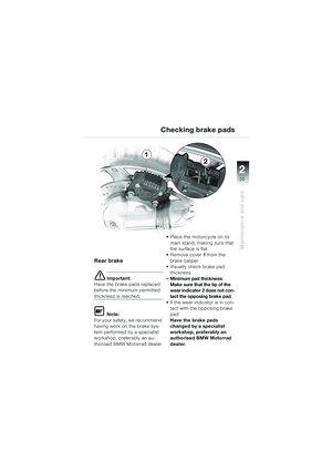
1
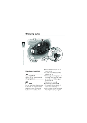
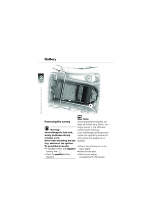
Removing the battery
d Warning:
Avoid damage to fuel tank,
wiring and hoses during
removal work.
Before disconnecting the bat-
tery, switch off the ignition.
To avoid short-circuits:
First disconnect the negative
battery lead (—),
then the positive battery
lead (+).
L Note:
Disconnecting the battery de-
letes all entries (e.g. faults, set-
tings) stored in the Motronic
control unit's memory.
Loss of settings can temporarily
impair the operating character-
istics when the engine is re-
started.
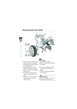
Place the motorcycle on its main stand
Remove the seat
Remove stowage compartment 1 for toolkit
Battery
20k41bkg3.book Seite 52 Mittwoch, 26. Mai 2004 3:33 15
Page 55 of 80
53
Maintenance and care
2
4
6
1
3
2
5
5
2
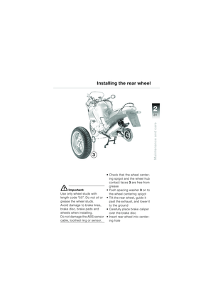
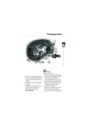
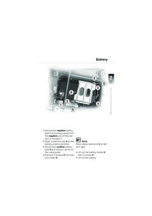
Disconnect negative battery
lead 1 and swing it away from
the negative post of the bat-
tery or insulate it
Open protective cap 4 for the
battery positive terminal
Disconnect positive battery
lead 3 and swing it up out of
the cable guide
Remove 2 screws 2 from bat-
tery holder 6
L Note:
Note rubber elements 5 on left
and right.
Lift out the battery holder 6
with 2 screws 2
Lift out the battery
Battery
20k41bkg3.book Seite 53 Mittwoch, 26. Mai 2004 3:33 15
Page 56 of 80
54
Maintenance and care
2
9
87
1
4
3
Battery
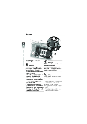
Installing the battery
d Warning:
Before connecting the bat-
tery, switch off the ignition.
To avoid short-circuits:
Connect the positive battery lead (+) 3 first
Close the protective cap at positive battery post 4
– Never install the battery without the protective cap.
Connect the negative bat- tery lead (—) 1
– The toolkit storage com-
partment must always be in
position, or else the protec-
tive cap for the positive bat-
tery lead could open.
d Warning:
Make sure that guard 7 is cor-
rectly positioned.
Make sure that brake fluid
hoses 8, 9 are correctly rout-
ed to avoid rubbing.
L Note:
Note rubber elements on left
and right.
Assembly is the reverse of the disassembly procedure
Switch on the ignition
Fully open the throttle once or twice
– The Motronic registers the
throttle-valve positions
20k41bkg3.book Seite 54 Mittwoch, 26. Mai 2004 3:33 15

 47
Maintenance and care
2
11
7
6
12
8
910Changing bulbs
Using a screwdriver, press in
one retaining lug 11 at left and
right, and open up the bulb
holder
Pull the H3 bulb out of bulb
ring 10
")
 48
Maintenance and care
2
e Attention:
Before changing a fuse, switch
off the ignition.
Never attempt to repair a blown
fuse – risk of fire!
For this reason, always carry a
number of spare fuses")
 49
Maintenance and care
2
Fuse assignment
Fuse box 1
1 Engine electronics ........ 10 A
2 Fuel pump, injection valves,
oxygen sensor,
diagnosis plug,
tank breather valve ........ 10 A
3 Horn, al")
 52
Maintenance and care
2
1
Removing the battery
d Warning:
Avoid damage to fuel tank,
wiring and hoses during
removal work.
Before disconnecting the bat-
tery, switch off the ignition.
To avoid sho")
 53
Maintenance and care
2
4
6
1
3
2
5
5
2
Disconnect negative battery
lead 1 and swing it away from
the negative post of the bat-
tery or insulate it
Open protective cap 4 for the
battery pos")
 54
Maintenance and care
2
9
87
1
4
3
Battery
Installing the battery
d Warning:
Before connecting the bat-
tery, switch off the ignition.
To avoid short-circuits:
Connect the positive battery lead (")