Page 280 of 578
4 - 18
ENGCYLINDER HEAD
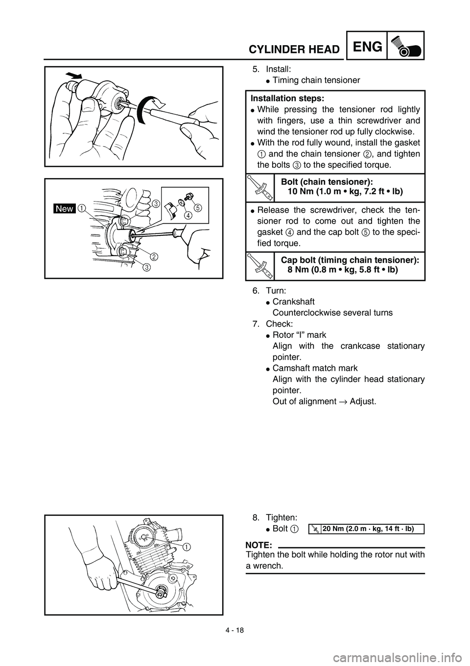
5. Install:
�Timing chain tensioner
6. Turn:
�Crankshaft
Counterclockwise several turns
7. Check:
�Rotor “I” mark
Align with the crankcase stationary
pointer.
�Camshaft match mark
Align with the cylinder head stationary
pointer.
Out of alignment → Adjust. Installation steps:
�While pressing the tensioner rod lightly
with fingers, use a thin screwdriver and
wind the tensioner rod up fully clockwise.
�With the rod fully wound, install the gasket
1 and the chain tensioner 2, and tighten
the bolts 3 to the specified torque.
T R..
Bolt (chain tensioner):
10 Nm (1.0 m • kg, 7.2 ft • lb)
�Release the screwdriver, check the ten-
sioner rod to come out and tighten the
gasket 4 and the cap bolt 5 to the speci-
fied torque.
T R..
Cap bolt (timing chain tensioner):
8 Nm (0.8 m • kg, 5.8 ft • lb)
8. Tighten:
�Bolt 1
NOTE:
Tighten the bolt while holding the rotor nut with
a wrench.
T R..20 Nm (2.0 m · kg, 14 ft · lb)
Page 326 of 578
4 - 41
ENGCLUTCH AND PRIMARY DRIVEN GEAR
EC498100
PRIMARY DRIVEN GEAR
Extent of removal:1 Primary driven gear removal2 Primary drive gear removal
Extent of removal Order Part name Q’ty Remarks
PRIMARY DRIVEN GEAR
REMOVAL
1 Nut (clutch boss) 1
Use special tool.
Refer to “REMOVAL POINTS”. 2 Lock washer 1
3 Clutch boss 1
4 Thrust plate 1
5 Primary driven gear 1
6 Thrust plate 1
7 Conical spring washer 1
8 Nut (primary drive gear) 1
Refer to “REMOVAL POINTS”.
9 Primary drive gear 1
10Straight key
1
2
1
Page 330 of 578
4 - 43
ENGCLUTCH AND PRIMARY DRIVEN GEAR
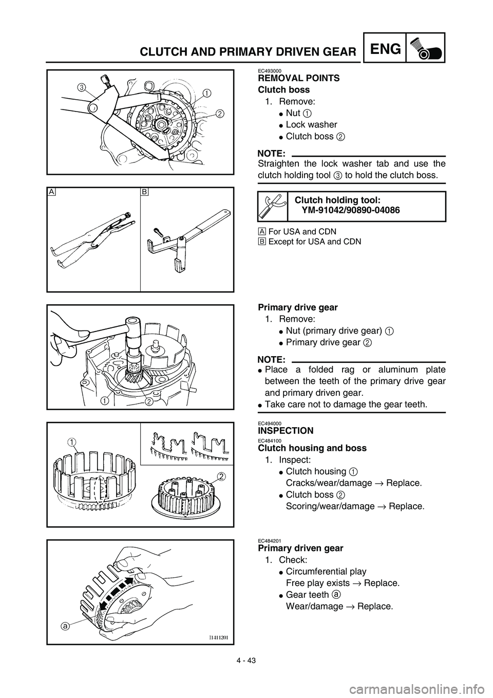
EC493000
REMOVAL POINTS
Clutch boss
1. Remove:
�Nut 1
�Lock washer
�Clutch boss 2
NOTE:
Straighten the lock washer tab and use the
clutch holding tool 3 to hold the clutch boss.
ÅFor USA and CDN
ıExcept for USA and CDN
Clutch holding tool:
YM-91042/90890-04086Å
ı
Primary drive gear
1. Remove:
�Nut (primary drive gear) 1
�Primary drive gear 2
NOTE:
�Place a folded rag or aluminum plate
between the teeth of the primary drive gear
and primary driven gear.
�Take care not to damage the gear teeth.
EC494000
INSPECTION
EC484100
Clutch housing and boss
1. Inspect:
�Clutch housing 1
Cracks/wear/damage → Replace.
�Clutch boss 2
Scoring/wear/damage → Replace.
EC484201
Primary driven gear
1. Check:
�Circumferential play
Free play exists → Replace.
�Gear teeth a
Wear/damage → Replace.
Page 336 of 578
4 - 46
ENGCLUTCH AND PRIMARY DRIVEN GEAR
Clutch
1. Install:
�Conical spring washer 1
�Thrust plate 2
�Primary driven gear 3
�Thrust plate 4
�Clutch boss 5
2. Install:
�Lock washer
�Nut (clutch boss) 1
NOTE:
Use the clutch holding tool 2 to hold the clutch
boss.
ÅFor USA and CDN
ıExcept for USA and CDN
3. Bend:
�Lock washer tab
Clutch holding tool:
YM-91042/90890-04086
New
T R..60 Nm (6.0 m · kg, 43 ft · lb)
Å
ı
4. Install:
�Friction plate 1
�Clutch plate 2
NOTE:
�Install the clutch plates and friction plates
alternately on the clutch boss, starting with a
friction plate and ending with a friction plate.
�Apply the engine oil on the friction plates and
clutch plates.
�Be sure to install a clutch plate with projec-
tion a offset approximately 90˚ from previ-
ous plates projection. Continue this
procedure in a clockwise direction until all
clutch plates are installed.
Page 340 of 578

4 - 48
ENGCLUTCH AND PRIMARY DRIVEN GEAR
9. Adjust:
�Push lever position
Adjustment steps:
�Loosen the locknut 1.
�Turn the push rod 1 2 clockwise or coun-
terclockwise to match alignment marks.
�Hold the push rod 1 to prevent it from
moving and tighten the locknut to specifi-
cation.
�Tighten the locknut 1.
T R..
Locknut:
8 Nm (0.8 m • kg, 5.8 ft • lb)
10. Install:
�Dowel pins
�Gasket (right crankcase cover)
�Right crankcase cover
�Battery negative lead 1
�Lead holder 2
�Bolts (right crankcase cover)
NOTE:
�Apply Quick gasket® (YAMAHA Bond
No.1215) to end of the right crankcase cover
bolts, as shown.
�Tighten the bolts in stages, using a criss-
cross pattern.
Quick gasket®:
ACC-QUICK-GS-KT
YAMAHA Bond No.1215:
90890-85505
New
T R..10 Nm (1.0 m · kg, 7.2 ft · lb)
11. Install:
�Kickstarter crank 1
�Nut (kickstarter crank) 2
NOTE:
Install the kickstarter crank so that there is 5 ~
10 mm (0.2 ~ 0.4 in) a between the kickstarter
crank and the right crankcase cover.
T R..50 Nm (5.0 m · kg, 36 ft · lb)
Page 356 of 578
4 - 56
ENGKICK AXLE AND SHIFT SHAFT
Shift shaft
1. Install:
�Shift shaft 1
NOTE:
�Apply the lithium soap base grease on the oil
seal lip of the left crankcase side.
�Hook the spring ends onto the stopper 2.
Kick axle assembly
1. Install:
�Kickstarter segment gear 1
�Plain washer 2
�Torsion spring 3
On kick axle 4.
NOTE:
Make sure the stopper a of the torsion spring
fits into the hole b on the kick axle.
2. Install:
�Spring guide 1
NOTE:
Slide the spring guide into the kick axle, make
sure the groove a in the spring guide fits on
the stopper of the torsion spring.
3. Install:
�Kick axle assembly 1
NOTE:
�Apply the engine oil on the kick axle.
�Slide the kick axle assembly into the crank-
case, make sure the clip 2 and kick axle
stopper b fit into their home positions a, c.
4. Hook:
�Torsion spring 1
NOTE:
Turn the torsion spring clockwise and hook
into the proper hole a in the crankcase.
Page 364 of 578

4 - 60
ENGCDI MAGNETO AND STARTER CLUTCH
3. Check:
�Starter clutch operation
�Install the starter clutch drive gear 1 onto
the starter clutch 2 and hold the starter
clutch.
�When turning the starter clutch drive gear
counterclockwise ı, the starter clutch and
the starter clutch drive gear should
engage. If the starter clutch drive gear and
starter clutch do not engage, the starter
clutch is faulty and must be replaced.
�When turning the starter clutch drive gear
clockwise Å, it should turn freely.
If the starter clutch drive gear does not
turn freely, the starter clutch is faulty and
must be replaced.
Å
ı
1
2
EC4L5000
ASSEMBLY AND INSTALLATION
CDI magneto
1. Install:
�Stator 1
�Bolt (stator)
�Lead guide
�Screw (lead guide) 2
�Pickup coil 3
�Bolt (pickup coil)
2. Install:
�Stater idle gear 1
�Plate 2
�Bolt 3
�Washer 4
NOTE:
Apply the engine oil on the starter idle gear
inner circumference.
T R..10 Nm (1.0 m · kg, 7.2 ft · lb)LT
T R..7 Nm (0.7 m · kg, 5.1 ft · lb)LT
T R..10 Nm (1.0 m · kg, 7.2 ft · lb)LT
4
1
2
3
ET R..7 Nm (0.7 m · kg, 5.1 ft · lb)
Page 432 of 578

REMOVAL POINTS
Brake fluid
1. Remove:
�Brake master cylinder cap 1
NOTE:
Do not remove the diaphragm.
2. Connect the transparent hose 2 to the
bleed screw 1 and pl")
5 - 14
CHASFRONT BRAKE (TT-R125LWE)
REMOVAL POINTS
Brake fluid
1. Remove:
�Brake master cylinder cap 1
NOTE:
Do not remove the diaphragm.
2. Connect the transparent hose 2 to the
bleed screw 1 and place a suitable con-
tainer under its end.
3. Loosen the bleed screw and drain the
brake fluid while pulling in the lever.
CAUTION:
�Do not reuse the drained brake fluid.
�Brake fluid may erode painted surfaces or
plastic parts. Always clean up spilled
fluid immediately.
Brake caliper
1. Remove:
�Brake caliper 1
NOTE:
Turn the brake caliper counterclockwise and
pull out it from the guide pin 2 on the brake
caliper bracket.
Brake caliper piston
1. Remove:
�Brake caliper piston
Use compressed air and proceed care-
fully.
WARNING
�Cover piston with rag and use extreme
caution when expelling piston from cylin-
der.
�Never attempt to pry out piston.
Brake caliper piston removal steps:
�Insert a piece of rag into the brake caliper
to lock one brake caliper.
�Carefully force the piston out of the brake
caliper cylinder with compressed air.