Page 26 of 578

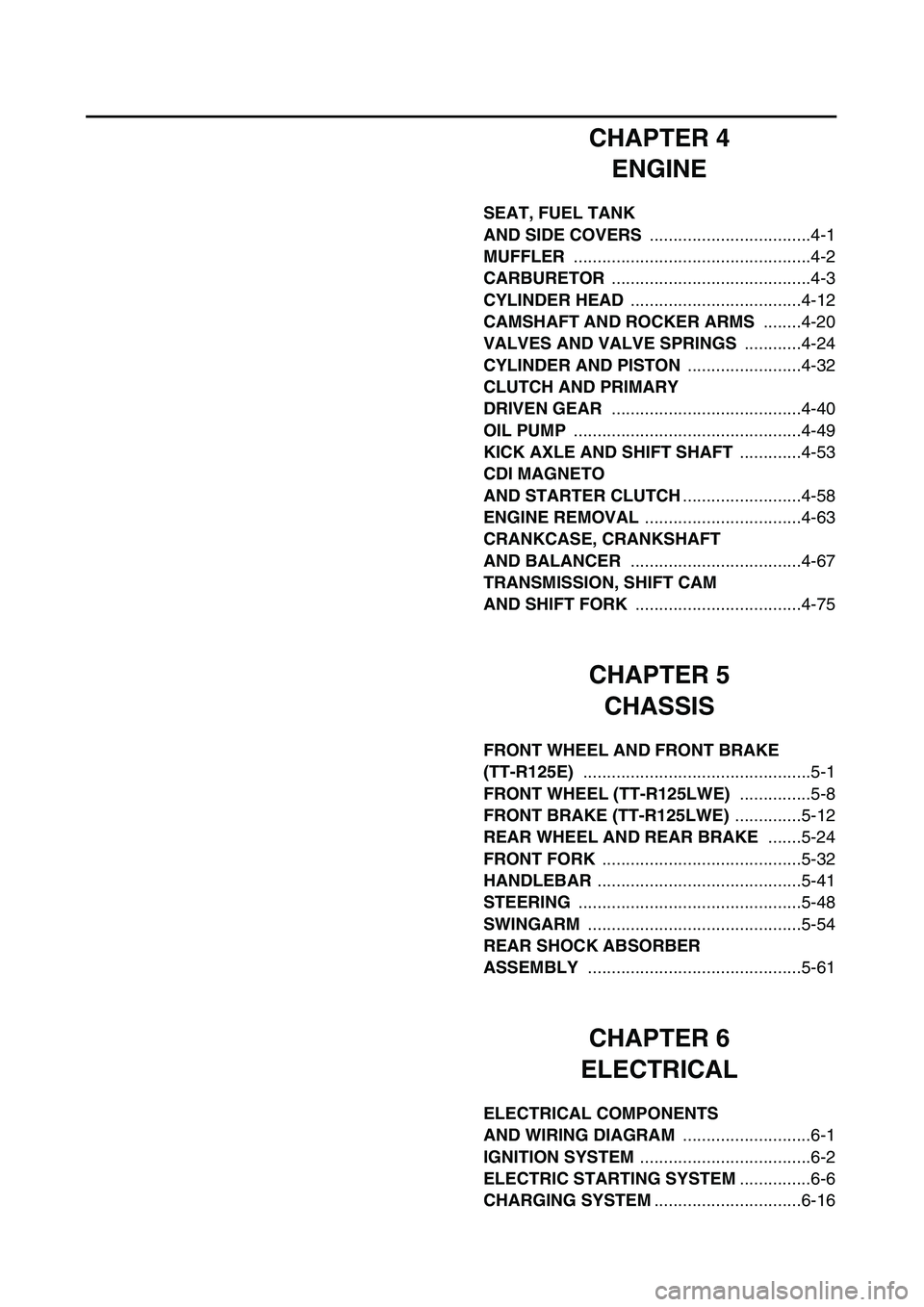
CHAPTER 4
ENGINE
SEAT, FUEL TANK
AND SIDE COVERS
..................................4-1
MUFFLER
..................................................4-2
CARBURETOR
..........................................4-3
CYLINDER HEAD
....................................4-12
CAMSHAFT AND ROCKER ARMS
........4-20
VALVES AND VALVE SPRINGS
............4-24
CYLINDER AND PISTON
........................4-32
CLUTCH AND PRIMARY
DRIVEN GEAR
........................................4-40
OIL PUMP
................................................4-49
KICK AXLE AND SHIFT SHAFT
.............4-53
CDI MAGNETO
AND STARTER CLUTCH
.........................4-58
ENGINE REMOVAL
.................................4-63
CRANKCASE, CRANKSHAFT
AND BALANCER
....................................4-67
TRANSMISSION, SHIFT CAM
AND SHIFT FORK
...................................4-75
CHAPTER 5
CHASSIS
FRONT WHEEL AND FRONT BRAKE
(TT-R125E)
................................................5-1
FRONT WHEEL (TT-R125LWE)
...............5-8
FRONT BRAKE (TT-R125LWE)
..............5-12
REAR WHEEL AND REAR BRAKE
.......5-24
FRONT FORK
..........................................5-32
HANDLEBAR
...........................................5-41
STEERING
...............................................5-48
SWINGARM
.............................................5-54
REAR SHOCK ABSORBER
ASSEMBLY
.............................................5-61
CHAPTER 6
ELECTRICAL
ELECTRICAL COMPONENTS
AND WIRING DIAGRAM
...........................6-1
IGNITION SYSTEM
....................................6-2
ELECTRIC STARTING SYSTEM
...............6-6
CHARGING SYSTEM
...............................6-16
Page 40 of 578
1 - 8
GEN
INFO
SPECIAL TOOLS
YM-4097, 90890-04097
YM-4098, 90890-04098
YM-04099, 90890-04099Valve guide remover
Valve guide installer
Valve guide reamer
These tools are needed to rebore the new valve
guide.YM-4097
YM-4098
YM-0409990890-04097
90890-04098
90890-04099
YM-34487
90890-06754Dynamic spark tester
Ignition checker
This instrument is necessary for checking the ignition
system components.YM-34487 90890-06754
ACC-QUICK-GS-KT
90890-85505Quick gasket
®
YAMAHA Bond No.1215
This sealant (Bond) is used for crankcase mating
surface, etc.ACC-QUICK-GS-KT 90890-85505
Part number Tool name/How to use Illustration
Page 56 of 578

1 - 13
GEN
INFO
STARTING AND BREAK-IN
EC190000
STARTING AND BREAK-IN
CAUTION:
Before starting the machine, perform the
checks in the pre-operation check list.
WARNING
Never start or run the engine in a closed
area. The exhaust fumes are poisonous;
they can cause loss of consciousness and
death in a very short time. Always operate
the machine in a well-ventilated area.
STARTING A COLD ENGINE
NOTE:
This model is equipped with an ignition circuit
cut-off system. The engine can be started
under the following conditions.
�When the transmission is in neutral.
�When the clutch is disengaged with the
transmission in any position. However, it is
recommended to shift into neutral before
starting the engine.
1. Shift the transmission into neutral.
2. Turn the fuel cock to “ON” and full open
the starter knob (CHOKE).
3. Turn the main switch to “ON”.
4. With the throttle completely closed start
the engine by pushing the start switch or
by kicking the kickstarter crank forcefully
with firm stroke.
5. Run the engine at idle or slightly higher
until it warms up: this usually takes about
one or two minutes.
6. The engine is warmed up when it
responds normally to the throttle with the
starter knob (CHOKE) turned off.
Page 74 of 578
SPEC
2 - 3
GENERAL SPECIFICATIONS
Brake:
Front brake type Drum brake
Operation Right hand operation
Rear brake type Drum brake
Operation Right foot operation
Suspension:
Front suspension Telescopic fork
Rear suspension Swingarm (link type monocross suspension)
Shock absorber:
Front shock absorber Coil spring/oil damper
Rear shock absorber Coil spring/gas, oil damper
Wheel travel:
Front wheel travel 180 mm (7.09 in)
Rear wheel travel 160 mm (6.30 in)
Electrical:
Ignition system CDI
Generator system CDI magneto
Battery type GT4L-BS
Battery voltage/capacity 12 V/3.2 AH
Specific gravity 1.320
Page 77 of 578
SPEC
2 - 6
GENERAL SPECIFICATIONS
Brake:
Front brake type Single disc brake
Operation Right hand operation
Rear brake type Drum brake
Operation Right foot operation
Suspension:
Front suspension Telescopic fork
Rear suspension Swingarm (link type monocross suspension)
Shock absorber:
Front shock absorber Coil spring/oil damper
Rear shock absorber Coil spring/gas, oil damper
Wheel travel:
Front wheel travel 180 mm (7.09 in)
Rear wheel travel 168 mm (6.61 in)
Electrical:
Ignition system CDI
Generator system CDI magneto
Battery type GT4L-BS
Battery voltage/capacity 12 V/3.2 AH
Specific gravity 1.320
Page 94 of 578

SPEC
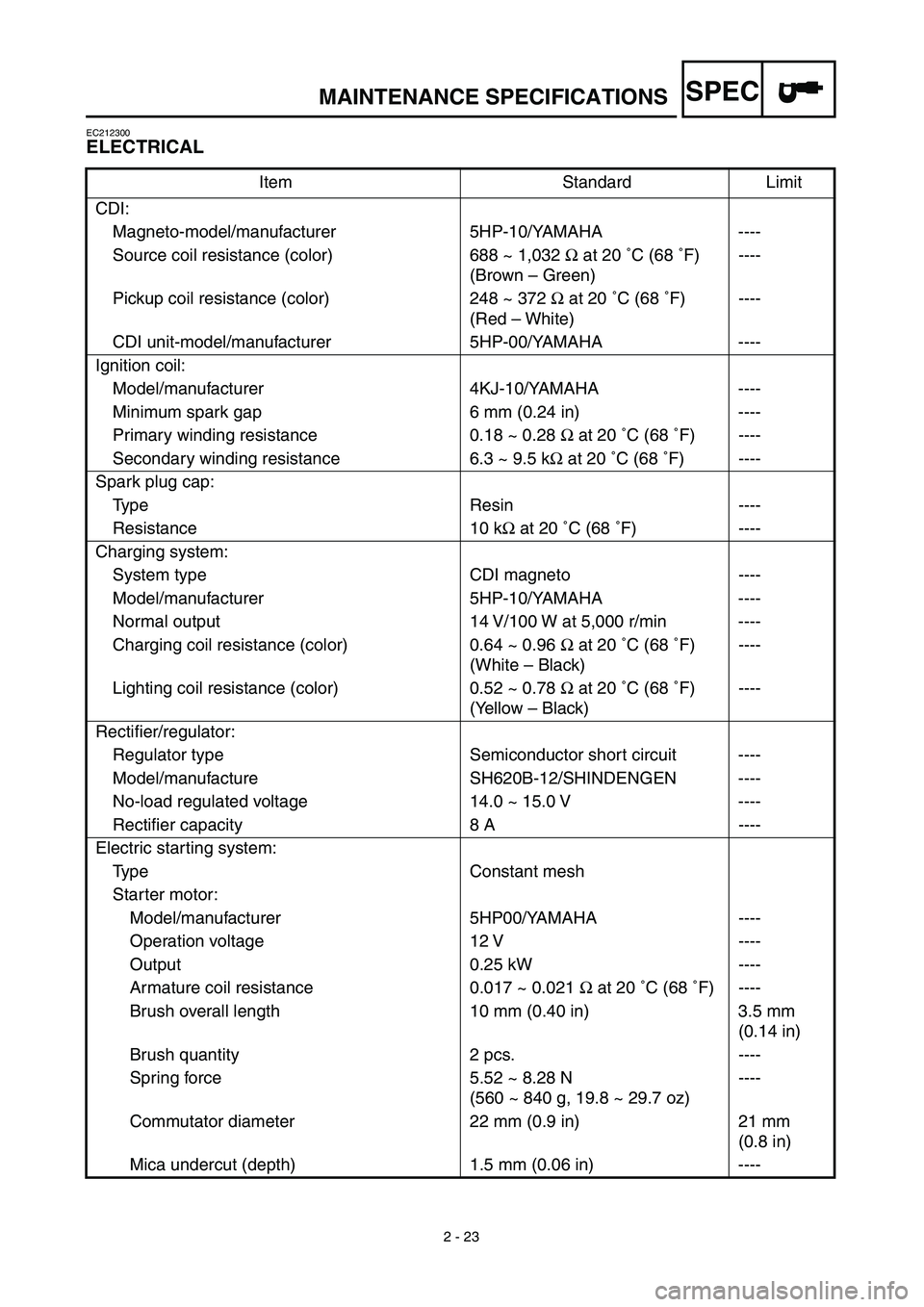
2 - 23
MAINTENANCE SPECIFICATIONS
EC212300
ELECTRICAL
Item Standard Limit
CDI:
Magneto-model/manufacturer 5HP-10/YAMAHA ----
Source coil resistance (color) 688 ~ 1,032 Ω at 20 ˚C (68 ˚F)
(Brown – Green)----
Pickup coil resistance (color) 248 ~ 372 Ω at 20 ˚C (68 ˚F)
(Red – White)----
CDI unit-model/manufacturer 5HP-00/YAMAHA ----
Ignition coil:
Model/manufacturer 4KJ-10/YAMAHA ----
Minimum spark gap 6 mm (0.24 in) ----
Primary winding resistance 0.18 ~ 0.28 Ω at 20 ˚C (68 ˚F) ----
Secondary winding resistance 6.3 ~ 9.5 kΩ at 20 ˚C (68 ˚F) ----
Spark plug cap:
Type Resin ----
Resistance 10 kΩ at 20 ˚C (68 ˚F) ----
Charging system:
System type CDI magneto ----
Model/manufacturer 5HP-10/YAMAHA ----
Normal output 14 V/100 W at 5,000 r/min ----
Charging coil resistance (color) 0.64 ~ 0.96 Ω at 20 ˚C (68 ˚F)
(White – Black)----
Lighting coil resistance (color) 0.52 ~ 0.78 Ω at 20 ˚C (68 ˚F)
(Yellow – Black)----
Rectifier/regulator:
Regulator type Semiconductor short circuit ----
Model/manufacture SH620B-12/SHINDENGEN ----
No-load regulated voltage 14.0 ~ 15.0 V ----
Rectifier capacity 8 A ----
Electric starting system:
Type Constant mesh
Starter motor:
Model/manufacturer 5HP00/YAMAHA ----
Operation voltage 12 V ----
Output 0.25 kW ----
Armature coil resistance 0.017 ~ 0.021 Ω at 20 ˚C (68 ˚F) ----
Brush overall length 10 mm (0.40 in) 3.5 mm
(0.14 in)
Brush quantity 2 pcs. ----
Spring force 5.52 ~ 8.28 N
(560 ~ 840 g, 19.8 ~ 29.7 oz)----
Commutator diameter 22 mm (0.9 in) 21 mm
(0.8 in)
Mica undercut (depth) 1.5 mm (0.06 in) ----
Page 95 of 578
SPEC
2 - 24
MAINTENANCE SPECIFICATIONS
Starter relay:
Model/manufacturer MS5F-751/JIDECO ----
Amperage rating 180 A ----
Coil winding resistance 4.2 ~ 4.6 Ω at 20 ˚C (68 ˚F) ----
Starting circuit cut-off relay:
Model/manufacturer ACM33221/MATSUSHITA ----
Coil winding resistance 75.69 ~ 92.51 Ω at 20 ˚C (68 ˚F) ----
Fuse (amperage × quantity):
Main fuse 10 A × 1 ----
Reserve fuse 10 A × 1 ----
Part to be tightened Thread size Q’tyTightening torque
Nm m•kg ft•lb
Pickup coil M6 × 1.0 2 10 1.0 7.2
Neutral switch M10 × 1.25 1 18 1.8 13
Stator M6 × 1.0 3 10 1.0 7.2
Rotor M12 × 1.25 1 80 8.0 58
Ignition coil M6 × 1.0 2 7 0.7 5.1
Starter motor M6 × 1.0 2 10 1.0 7.2 Item Standard Limit
Page 156 of 578
2 - 30
SPEC
‰Fasten the starter motor lead.
ÏPass the engine oil breather
hose and overflow hose
between the right half of the
swingarm and frame.
ÌPass the negative battery lead
on the inside of the frame as
shown.
ÓFasten the engine oil breather
hose, overflow hose and air
vent hoses to 2 clicks.ÈAfter fastening the starter cable,
push it against the starter
plunger.
ÔPut the tip of the air vent hose
into the frame.
Install the primary coil terminal
(orange) to the ignition coil.
ÒFasten the ground lead together
with the ignition coil.
1
2
3
4
5
6
7
8
9
0
6 ABC6DEFGÅ
ı
Ç
Î
‰ Ï ÌÓÈÔÒ
CABLE ROUTING DIAGRAM