Page 166 of 578

3 - 3
INSP
ADJ
PRE-OPERATION INSPECTION AND MAINTENANCE
PRE-OPERATION INSPECTION AND MAINTENANCE
Before riding for break-in operation or practice, make sure the machine is in good operating condi-
tion.
Before using this machine, check the following points.
GENERAL INSPECTION AND MAINTENANCE
Item Routine Page
FuelCheck that a fresh gasoline is filled in the fuel tank. Check the
fuel line for leakage.P.1-12
Engine oilCheck that the oil level is correct. Check the crankcase for leak-
age.P.3-7 ~ 10
Gear shifter and clutchCheck that gears can be shifted correctly in order and that the
clutch operates smoothly.P.3-4
Throttle grip/housingCheck that the throttle grip operation and free play are correctly
adjusted. Lubricate the throttle grip and housing, if necessary.P.3-4 ~ 5
BrakesCheck the play of front and rear brake and effect of front and
rear brake.
Check fluid level and leakage. (TT-R125LWE only)P.3-15 ~ 20
Drive chainCheck chain slack and alignment. Check that the chain is lubri-
cated properly.P.3-21 ~ 22
WheelsCheck for excessive wear and tire pressure. Check for loose
spokes and have no excessive play.P.3-27 ~ 28
SteeringCheck that the handlebar can be turned smoothly and have no
excessive play.P.3-28 ~ 30
Front forks and rear shock
absorber assemblyCheck that they operate smoothly and there is no oil leakage. P.3-23 ~ 26
Cables (wires)Check that the clutch and throttle cables move smoothly. Check
that they are not caught when the handlebars are turned or
when the front forks travel up and down.—
Muffler Check that the muffler is tightly mounted and has no cracks. P.4-2
Sprocket Check that the driven sprocket tightening nut is not loose. P.3-20
Lubrication Check for smooth operation. Lubricate if necessary. P.3-31
Bolts and nuts Check the chassis and engine for loose bolts and nuts. —
Lead connectorsCheck that the CDI magneto, CDI unit, and ignition coil are con-
nected tightly.P.1-5
Page 244 of 578
3 - 40
INSP
ADJ
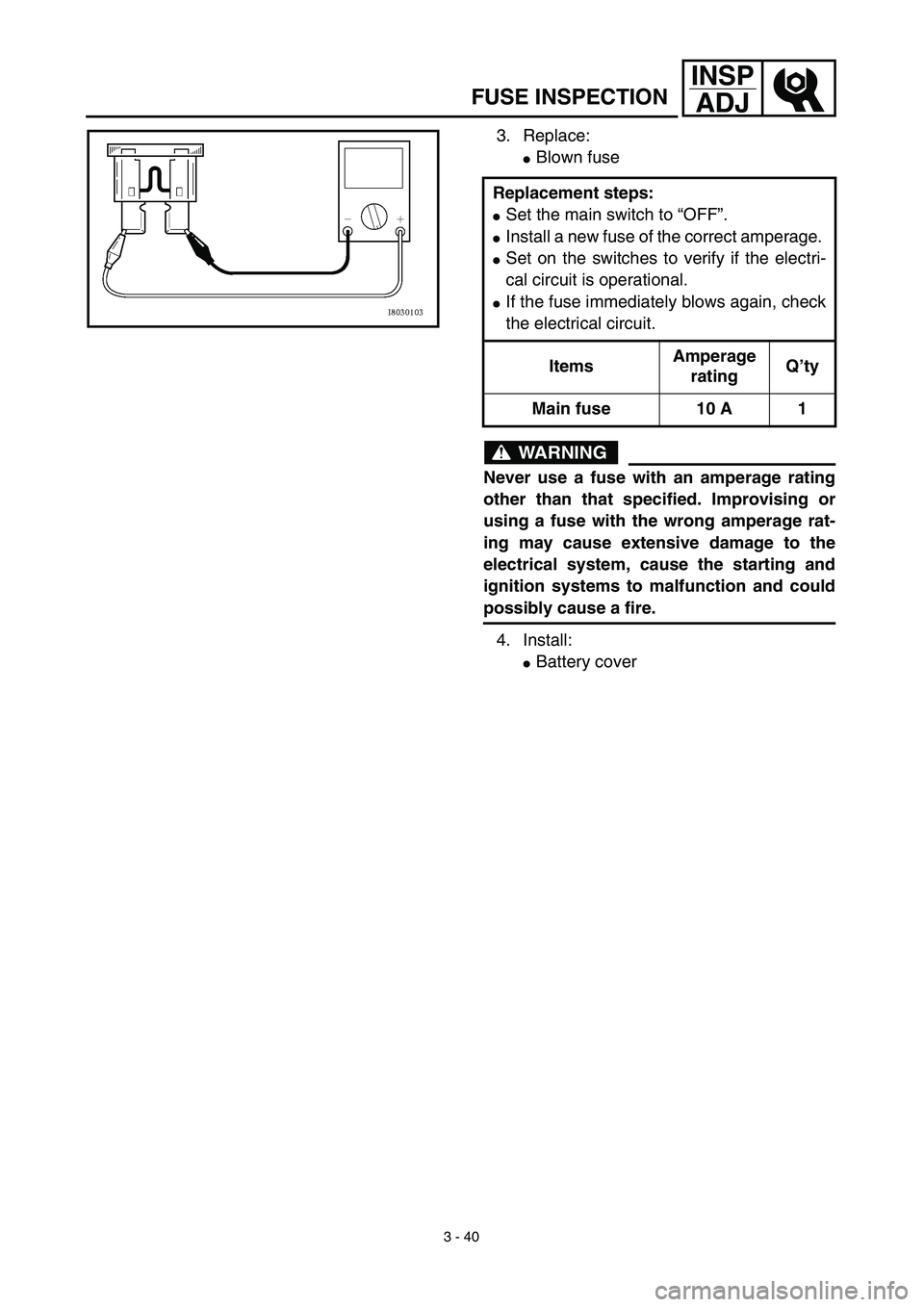
3. Replace:
�Blown fuse
WARNING
Never use a fuse with an amperage rating
other than that specified. Improvising or
using a fuse with the wrong amperage rat-
ing may cause extensive damage to the
electrical system, cause the starting and
ignition systems to malfunction and could
possibly cause a fire.
4. Install:
�Battery cover Replacement steps:
�Set the main switch to “OFF”.
�Install a new fuse of the correct amperage.
�Set on the switches to verify if the electri-
cal circuit is operational.
�If the fuse immediately blows again, check
the electrical circuit.
ItemsAmperage
ratingQ’ty
Main fuse 10 A 1
FUSE INSPECTION
Page 536 of 578

6 - 1
–+ELEC
* The illustration shows the TT-R125LWE
12345 7 6890A
EDCB
ELECTRICAL COMPONENTS AND WIRING DIAGRAM
EC600000
ELECTRICAL
EC610000
ELECTRICAL COMPONENTS AND WIRING DIAGRAM
EC611000
ELECTRICAL COMPONENTS
1
CDI unit
2
Main switch
3
Start switch
4
Clutch switch
5
Engine stop switch
6
Starting circuit cut-off
relay
7
Ignition coil
8
Battery
9
Starter relay
0
Fuse
A
Rectifier/regulator
B
Neutral switch
C
CDI magneto
D
Starter motor
E
Spark plug
COLOR CODE
B ...................... Black
Br ..................... Brown
G...................... Green
O...................... Orange
R ...................... Red
Sb .................... Sky blueW ..................... White
Y ...................... Yellow
B/W.................. Black/White
L/Y ................... Blue/Yellow
R/W ................. Red/White
EC612000
WIRING DIAGRAM
B
R/W
WB
RYW
BR Y
10A
R
BR/W
ON
OFFR
BrRB/WBB/WBr B
ON OFF
R/WBr BB
R/WSbR/W
BB BL/Y
OFF RUN
BBBB/W
W
YWSbBSbY B
G
WBrRG
WBrRB
B/WR
W Br
GO
R
SbR/WR/WR/WR/W
R/W
B
R
B/WBrBr
B
L/Y
BSb
YW
RWBrG
RWBrG
B/W
B/W
BOO
B
B
1
2
3
45 67
8
90 A
BC
DE
Page 538 of 578
–+ELEC
6 - 2
IGNITION SYSTEM
EC620000
IGNITION SYSTEM
INSPECTION STEPS
Use the following steps for checking the possibility of the malfunctioning engine being attributable to
ignition system failure and for checking the spark plug which will not spark.
*marked: Only when the ignition checker is used.
NOTE:
�
Remove the following parts before inspection.
1) Seat
2) Fuel tank
�
Use the following special tools in this inspection.
Dynamic spark tester:
YM-34487
Ignition checker:
90890-06754
Pocket tester:
YU-3112-C/90890-03112
Spark gap test*Clean or replace
spark plug.
Check entire ignition
system for connection.Repair or replace.
Check main switch. Replace.
Check engine stop switch. Replace.
Check ignition coil. Primary coil Replace.
Secondary coil Replace.
Check CDI magneto. Pickup coil Replace.
Source coil Replace.
Replace CDI unit.
No Spark
OK
OK
OK
OK
Spark
No good
No good
No good
No good
No good
No good
OK
No good
Page 542 of 578
6 - 3
–+ELEC
IGNITION SYSTEM
EC622001
SPARK GAP TEST
1. Disconnect the spark plug cap from spark
plug.
2. Connect the dynamic spark tester
1
(ignition checker
2
) as shown.
�
Spark plug cap
3
�
Spark plug
4
Å
For USA and CDN
ı
Except for USA and CDN
3. Kick the kick starter.
4. Check the ignition spark gap.
5. Start engine, and increase spark gap until
misfire occurs. (for USA and CDN only)
Minimum spark gap:
6.0 mm (0.24 in)
Å
ı
EC624000
COUPLERS AND LEADS CONNECTION
INSPECTION
1. Check:
�
Couplers and leads connection
Rust/dust/looseness/short-circuit
→
Repair or replace.
MAIN SWITCH INSPECTION
1. Inspect:
�
Main switch continuity
Check for continuity as follows:
Incorrect continuity
→
Replace.
Tester (+)
→
Red lead
1
Tester (–)
→
Brown lead
2
Continuous
Tester (+)
→
Black/White lead
3
Tester (–)
→
Black lead
4
Continuous
R
1
Br
2
B/W
3
B
4Tester selec-
tor position
ON
Ω × 1
OFF
RB/W
BrB
13
24
Page 544 of 578
6 - 4
–+ELECIGNITION SYSTEM
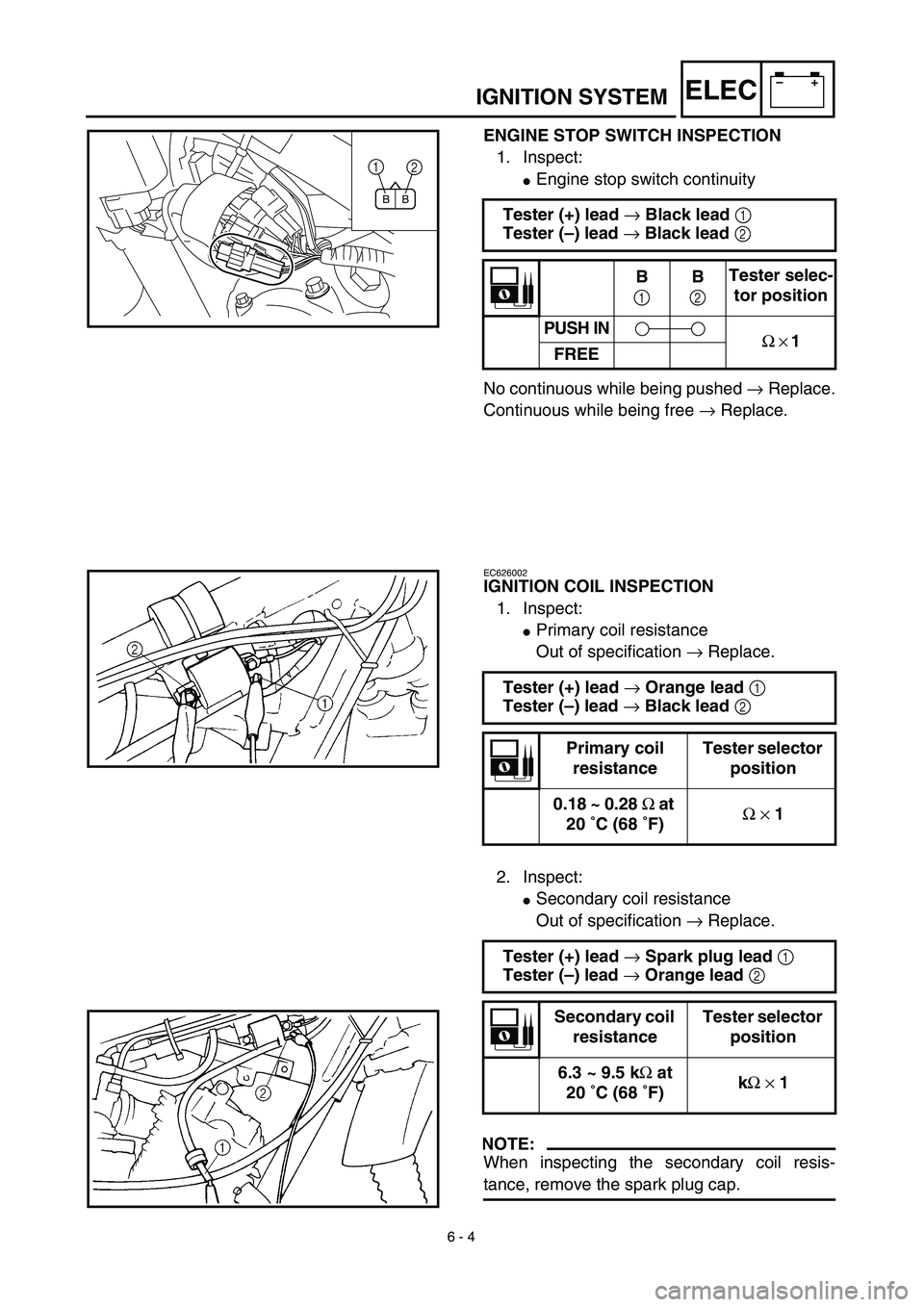
ENGINE STOP SWITCH INSPECTION
1. Inspect:
�Engine stop switch continuity
No continuous while being pushed → Replace.
Continuous while being free → Replace. Tester (+) lead → Black lead 1
Tester (–) lead → Black lead 2
B
1B
2Tester selec-
tor position
PUSH IN
Ω × 1
FREE
BB
1
2
EC626002
IGNITION COIL INSPECTION
1. Inspect:
�Primary coil resistance
Out of specification → Replace.
2. Inspect:
�Secondary coil resistance
Out of specification → Replace.
NOTE:
When inspecting the secondary coil resis-
tance, remove the spark plug cap.Tester (+) lead → Orange lead 1
Tester (–) lead → Black lead 2
Primary coil
resistanceTester selector
position
0.18 ~ 0.28 Ω at
20 ˚C (68 ˚F)Ω × 1
Tester (+) lead → Spark plug lead 1
Tester (–) lead → Orange lead 2
Secondary coil
resistanceTester selector
position
6.3 ~ 9.5 kΩ at
20 ˚C (68 ˚F)kΩ × 1
Page 546 of 578
6 - 5
–+ELECIGNITION SYSTEM
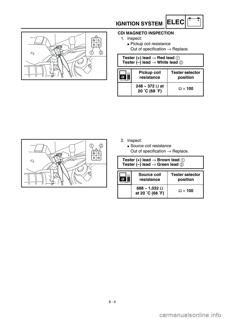
CDI MAGNETO INSPECTION
1. Inspect:
�Pickup coil resistance
Out of specification → Replace.
Tester (+) lead → Red lead 1
Tester (–) lead → White lead 2
Pickup coil
resistanceTester selector
position
248 ~ 372 Ω at
20 ˚C (68 ˚F)Ω × 100
Br G
RW
12
2. Inspect:
�Source coil resistance
Out of specification → Replace.
Tester (+) lead → Brown lead 1
Tester (–) lead → Green lead 2
Source coil
resistanceTester selector
position
688 ~ 1,032 Ω
at 20 ˚C (68 ˚F)Ω × 100
Br G
RW
1
2