Page 294 of 2234

A78512
(d)
A78513
(g)
(h)
±
ENGINE CONTROL SYSTEMTHROTTLE BODY ASSY(1AZ±FSE)
10±45
AVENSIS REPAIR MANUAL (RM1018E)
(b)Remove the bolt, and then remove the ground terminal.
(c)Remove th")
A78511
(b)
A78512
(d)
A78513
(g)
(h)
±
ENGINE CONTROL SYSTEMTHROTTLE BODY ASSY(1AZ±FSE)
10±45
AVENSIS REPAIR MANUAL (RM1018E)
(b)Remove the bolt, and then remove the ground terminal.
(c)Remove the 4 bolts, and then remove the throttle body
bracket.
(d)Disconnect the throttle motor connector.
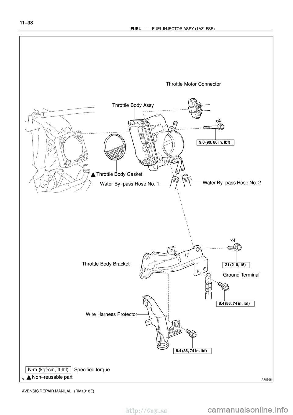
(e)Remove the 4 bolts, and then remove the throttle body.
(f)Remove the gasket from the intake manifold.
(g)Disconnect the water by±pass hose No. 1.
(h)Disconnect the water by±pass hose No. 2.
7.INSTALL THROTTLE BODY ASSY
(a)Connect the water by±pass hose No. 2.
(b)Connect the water by±pass hose No. 1.
(c)Install a new gasket to the intake manifold.
(d)Install the throttle body with the 4 bolts. Torque: 9.0 N �m (90 kgf�cm, 80 in. �lbf)
(e)Connect the throttle motor connector.
(f)Install the throttle body bracket with the 4 bolts. Torque: 21 N �m (210 kgf�cm, 15 ft�lbf)
(g)Install the ground terminal with the bolt. Torque: 8.4 N �m (86 kgf�cm, 74 in. �lbf)
(h)Install the wire harness protector with the bolt. Torque: 8.4 N �m (86 kgf�cm, 74 in. �lbf)
8.INSTALL AIR CLEANER CAP SUB±ASSY Torque: 1.5 N �m (15 kgf�cm, 13 in. �lbf)
9.INSTALL ENGINE COVER SUB±ASSY NO.1 Torque: 7.0 N �m (71 kgf�cm, 62 in. �lbf)
10.ADD ENGINE COOLANT (See page 16±31)
11.CHECK FOR ENGINE COOLANT LEAKS (See page 16±25)
12. INSTALL ENGINE ROOM COVER SIDE
http://vnx.su
Page 320 of 2234
A78508� Non±reusable part
N´m (kgf´cm, ft´lbf) : Specified torque Throttle Body Assy
Throttle Motor Connector
� Throttle Body Gasket
Water By±pass Hose No. 2
Water By±pass Hose No. 1
9.0 (90, 80 in.� lbf)
x4
x4
21 (210, 15)Throttle Body Bracket
8.4 (86, 74 in.� lbf)
Ground Terminal
Wire Harness Protector
8.4 (86, 74 in.�lbf)
11±38
±
FUEL FUEL INJECTOR ASSY (1AZ±FSE)
AVENSIS REPAIR MANUAL (RM1018E)
http://vnx.su
Page 331 of 2234
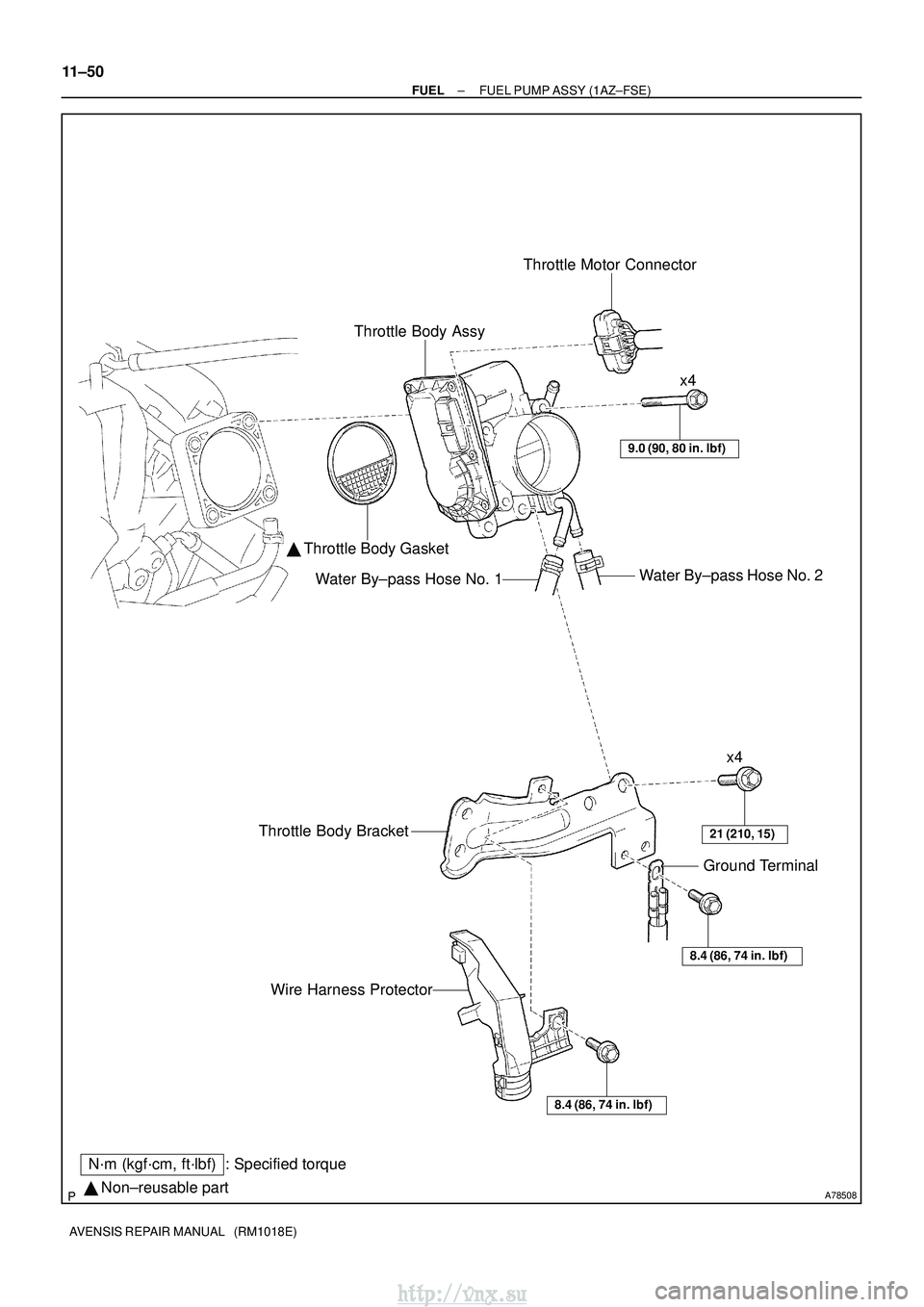
A78508� Non±reusable part
N´m (kgf´cm, ft´lbf) : Specified torque Throttle Body Assy
Throttle Motor Connector
� Throttle Body Gasket
Water By±pass Hose No. 2
Water By±pass Hose No. 1
9.0 (90, 80 in.� lbf)
x4
x4
21 (210, 15)Throttle Body Bracket
8.4 (86, 74 in.� lbf)
Ground Terminal
Wire Harness Protector
8.4 (86, 74 in.�lbf)
11±50
±
FUEL FUEL PUMP ASSY (1AZ±FSE)
AVENSIS REPAIR MANUAL (RM1018E)
http://vnx.su
Page 409 of 2234

AVENSIS REPAIR MANUAL (RM1018E)
INSPECTION
1. INSPEC")
1209J±02
A77127
Ohmmeter
Resistance
A77128No Continuity Ohmmeter
A77129
Vacuum
A77130
6V
Vacuum
12±18
±
EMISSION CONTROL EGR SYSTEM (1CD±FTV)
AVENSIS REPAIR MANUAL (RM1018E)
INSPECTION
1. INSPECT VACUUM REGULATING VALVE ASSY
(a) Inspect E±VRV for open circuit (1) Using an ohmmeter, measure resistance betweenthe terminals.
Resistance:
10 to 14 � at 20 �C (68� F)
(b) Inspect E±VRV for ground (1) Using an ohmmeter, check that there is no continu-ity between each terminal and the body.
Specified condition : No continuity
(c) Inspect E±VRV for air tightness (1) Apply vacuum to the vacuum output port. Checkthat the needle of vacuum pump indicates an in-
crease of 66.7 kPa (500 mmHg, 19.7 in.Hg) or
more.
If the air tightness is not as specified, replace the E±VRV.
(d) Inspect E±VRV operation (1) Apply about 4 dry batteries of 1.5V in series.
(2) Check that the need does not move when vacuumis applied to the vacuum outlet port.
If operation is not as specified, replace the E±VRV.
http://vnx.su
Page 413 of 2234

12±9
AVENSIS REPAI")
A77115
Ohmmeter
Resistance
A77116
Ohmmeter
No continuity
A77117
Air
E
F
A77118
Air
E
F
Battery
A61829
+BHT
E1
Bank 1 Sensor 1:
±
EMISSION CONTROL EMISSION CONTROL SYSTEM (1AZ±FE)
12±9
AVENSIS REPAIR MANUAL (RM1018E)
4. INSPECT VACUUM SWITCHING VALVE ASSY NO.1
(a) Inspect VSV for open circuit.
(1) Using an ohmmeter, measure resistance between
the terminals.
Resistance: 26 to 30 � at 20 �C (68� F)
If the resistance is not as specified, replace the VSV.
(b) Inspect the VSV for ground. (1) Using an ohmmeter, check that there is no continu-
ity between each terminal and the body.
If there is continuity, replace the VSV.
(c) Inspect the VSV operation. (1) Check that air flows with a little difficulty from port Eto port F.
(2) Apply battery voltage across the terminals.
(3) Check that air flows from port E to port F.
If operation is not as specified, replace the VSV.
5. INSPECT AIR FUEL RATIO SENSOR
(a) Bank 1 Sensor 1: (1) Using an ohmmeter, measure the resistance be-
tween the terminals.
Resistance:
Terminal No.Resistance
1 (HT) ± 2 (+B)1.8 to 3.4 � at 20 �C (68 �F)
1 (HT) ± (+B)5.0 to 7.5 � at 500 � C (932 �F)
1 (HT) ± 4 (E1)No Continuity
If the resistance is not as specified, replace the sensor.
http://vnx.su
Page 418 of 2234

AVENSIS RE")
A77115
Ohmmeter
Resistance
A77116
Ohmmeter
No continuity
A77117
Air
E
F
A77118
Air
E
F
Battery
A64543
+B
Bank 2 Sensor 1: HT
E1
12±14
±
EMISSION CONTROL EMISSION CONTROL SYSTEM (1AZ±FSE)
AVENSIS REPAIR MANUAL (RM1018E)
4. INSPECT VACUUM SWITCHING VALVE ASSY NO.1
(a) Inspect VSV for open circuit. (1) Using an ohmmeter, measure resistance between
the terminals.
Resistance: 26 to 30 � at 20 �C (68� F)
If the resistance is not as specified, replace the VSV.
(b) Inspect the VSV for ground. (1) Using an ohmmeter, check that there is no continu-
ity between each terminal and the body.
If there is continuity, replace the VSV.
(c) Inspect the VSV operation. (1) Check that air flows with a little difficulty from port Eto port F.
(2) Apply battery voltage across the terminals.
(3) Check that air flows from port E to port F.
If operation is not as specified, replace the VSV.
5. INSPECT HEATED OXYGEN SENSOR
(a) Bank 2 Sensor 1: (1) Using an ohmmeter, measure the resistance be-
tween the terminals.
Resistance:
Terminal No.Resistance
1 (HT) ± 2 (+B)11 to 16 � at 20 �C (68 �F)
1 (HT) ± 4 (E1)No Continuity
If the resistance is not as specified, replace the sensor.
http://vnx.su
Page 423 of 2234

12±3
AVENSIS REPAIR MANUAL")
1209D±02
A62250
Port APort BPort C
A77115
Ohmmeter
Resistance
A77116
Ohmmeter
No continuity
A77117
Air
E
F
±
EMISSION CONTROL EMISSION CONTROL SYSTEM (1ZZ±FE/3ZZ±FE)
12±3
AVENSIS REPAIR MANUAL (RM1018E)
INSPECTION
1. INSPECT CHARCOAL CANISTER ASSY
(a) Inspect charcoal canister operation.
(1) Check the charcoal canister operation according tothe table below.
SST 09992±00242
Inspection:
Checking methodResult
Close ports B and C, then apply vacuum
to port ANo leaks
Close port C, then apply vacuum to port
AAir flows from port B
Close port C, then blow air into port AAir flows from port B
Blow air into port AAir flows from ports B and C
2. INSPECT VACUUM SWITCHING VALVE ASSY NO.1
(a) Inspect VSV for open circuit. (1) Using an ohmmeter, measure resistance betweenthe terminals.
Resistance: 26 to 30 � at 20 �C (68� F)
If the resistance is not as specified, replace the VSV.
(b) Inspect the VSV for ground. (1) Using an ohmmeter, check that there is no continu-ity between each terminal and the body.
If there is continuity, replace the VSV.
(c) Inspect the VSV operation.
(1) Check that air flows with a little difficulty from port Eto port F.
http://vnx.su
Page 432 of 2234
13030±02
A60591
A60592
A60593
Air
E G
A60594
Air
Filter Battery
E
±
INTAKE TURBO CHARGER SYSTEM (1CD±FTV)
13±7
AVENSIS REPAIR MANUAL (RM1018E)
INSPECTION
1. VACUUM SWITCHING VALVE ASSY NO.1
(a) Inspect VSV for open circuit.
(1) Using an ohmmeter, check that the there is continu-ity between the terminals.
Resistance: 37 ± 44 � at 20 �C (68� F)
(b) Inspect VSV for ground. (1) Using an ohmmeter, check that there is no continu-ity between each terminal and the body.
Specified condition: No continuity
(c) Inspect VSV operation. (1) Check that air flows from port E to G.
(2) Apply battery voltage across the terminals.
(3) Check that air flows from port E to filter.
http://vnx.su

13±7
AVENSIS REPAIR MANUAL (RM1018E)
INSPECTION
1. VACUUM SWITCHING VALVE ASSY NO.1
(a)")