Page 604 of 2234

14±183
AVENSIS REPAIR MANUAL (RM1018E)
(e)Inspect cylinder compression pressure.
SST09992±00500
(1)Insert a compression gauge into the spark plughole.
(")
A79033
±
ENGINE MECHANICALENGINE(1AZ±FSE)
14±183
AVENSIS REPAIR MANUAL (RM1018E)
(e)Inspect cylinder compression pressure.
SST09992±00500
(1)Insert a compression gauge into the spark plughole.
(2)Fully open the throttle.
(3)While cranking the engine, measure the compres- sion pressure.
Compression pressure:
1,300 kPa (13.3 kgf/cm
2, 189 psi)
Minimum pressure:
1000 kPa (10.2 kgf/cm
2, 145 psi)
Difference between each cylinder:
100 kPa (1.0 kgf/cm
2, 14 psi)
NOTICE:
�Always use a fully charged battery to obtain engine
speed of 250 rpm or more.
�Check other cylinder's compression pressure in the
same way.
�This measurement must be done in as short a time as
possible.
(4)If the cylinder compression is low, pour a small amount of engine oil into the cylinder through the
spark plug hole and inspect again.
HINT:
�If adding oil increases the compression, the piston rings
and/or cylinder bore may be worn or damaged.
�If pressure stays low, a valve may be sticking or seating
improperly, or there may be leakage past the gasket.
10.INSPECT CO/HC
(a)Start the engine.
(b)Run the engine at 2,500 rpm for approximately 180 seconds.
(c)Insert CO/HC meter testing probe at least 40 cm (1.3 ft) into the tail\
pipe during idling.
(d)Check CO/HC concentration at idle. Idle CO concentration: 0 to 0.5 %
Idle HC concentration: Applicable local regulation
(e)If the CO/HC concentration does not conform to specifications, perform troubleshooting in the order given below.
(1)Check heated oxygen sensor operation. (See page 12±6)
(2) See the table below for possible causes, and then inspect and repair the applicable causes ifnecessary.
http://vnx.su
Page 611 of 2234

14±3
AVENSIS REPAIR MANUAL (RM1018E)
(3) While cranking the engine, measure the compres-
sion pressure.
Compression pressure
�
1,300 kPa (13.3 kgf �cm")
±
ENGINE MECHANICAL ENGINE (1ZZ±FE/3ZZ±FE)
14±3
AVENSIS REPAIR MANUAL (RM1018E)
(3) While cranking the engine, measure the compres-
sion pressure.
Compression pressure
�
1,300 kPa (13.3 kgf �cm
2, 189 psi)
Minimum pressure: 1,000 kPa (10.2 kgf �cm
2, 145 psi)
Difference between each cylinder:
100 kPa (1.0 kgf �cm
2, 14 psi)
NOTICE:
�Always use a fully charged battery to obtain engine
speed of 250 rpm or more.
�Check other cylinder's compression pressure in the
same way.
�This measurement must be done in as short a time as
possible.
(4) If the cylinder compression in one or more cylinders is low, pour a small amount of engine oil into the cyl-
inder through the spark plug hole and repeat steps
(1) through (3) for the cylinders that have low com-
pression.
HINT:
�If adding oil helps increase the compression, the piston
rings and/or cylinder bore may be worn or damaged.
�If pressure stays low, a valve may be sticking or seating
improperly, or there may be leakage past the gasket.
10. INSPECT CO/HC
(a) Start the engine.
(b) Run the engine at 2,500 rpm for approximately 180 seconds.
(c) Insert CO/HC meter testing probe at least 40 cm (1.3 ft) into the tail\
pipe during idling.
(d) Check CO/HC concentration at idle.
Idle CO concentration: 0 to 0.5 %
Idle HC concentration: Applicable local regulation
If the CO/HC concentration does not conform to specifications, perform tro\
ubleshooting in the order given
below.
�Check heated oxygen sensor operation.
�See the table below for possible causes, and then inspect and repair the applicable causes if
necessary.
http://vnx.su
Page 693 of 2234
A76722
A76723
A64033
A64034
A64034
±
ENGINE MECHANICAL PARTIAL ENGINE ASSY (1ZZ±FE/3ZZ±FE)
14±37
AVENSIS REPAIR MANUAL (RM1018E)
85. REMOVE EXHAUST MANIFOLD HEAT INSULATOR
NO.1
(a) Disconnect the heated oxygen sensor connector.
(b) Remove the 3 bolts and the nut, and then remove the ex-
haust manifold heat insulator.
86. REMOVE EXHAUST MANIFOLD
(a) Remove the 5 nuts, then remove the exhaust manifold and the gasket.
87. REMOVE ENGINE COOLANT TEMPERATURE SENSOR
(a) Using SST, remove the engine coolant temperature sen- sor.
SST 09817±33190
88. REMOVE RADIO SETTING CONDENSER
(a) Remove the bolt and the condenser.
89. REMOVE WATER BY±PASS HOSE NO.2
90. REMOVE RADIATOR HOSE INLET
91. REMOVE HEATER INLET WATER HOSE
92. REPLACE PARTIAL ENGINE ASSY
93. INSTALL RADIO SETTING CONDENSER
(a) Install the condenser with the bolt. Torque: 10 N �m (102 kgf� cm, 7 ft�lbf)
http://vnx.su
Page 694 of 2234

AVENSIS REPAIR MANUAL (RM1018E)
94. INSTALL ENGINE COOLANT TEMPERATURE SENSOR
(a) Install a n")
A64033
A76723
A76722
A76721
A76720
ABB
14±38
±
ENGINE MECHANICAL PARTIAL ENGINE ASSY (1ZZ±FE/3ZZ±FE)
AVENSIS REPAIR MANUAL (RM1018E)
94. INSTALL ENGINE COOLANT TEMPERATURE SENSOR
(a) Install a new gasket to the engine coolant temperature
sensor.
(b) Using SST, install the engine coolant temperature sensor. SST 09817±33190
Torque: 20 N� m (204 kgf�cm, 15 ft�lbf)
95. INSTALL EXHAUST MANIFOLD
(a) Install a new gasket and the exhaust manifold with the 5 nuts.
Torque: 37 N �m (377 kgf� cm, 27 ft�lbf)
96. INSTALL EXHAUST MANIFOLD HEAT INSULATOR NO.1
(a) Install the exhaust manifold heat insulator,then install the 3 bolts and nut.
Torque:
18 N�m (184 kgf� cm, 13 ft�lbf) for Bolt
12 N� m (122 kgf� cm, 9 ft�lbf) for Nut
(b) Connect the heated oxygen sensor connector.
97. INSTALL MANIFOLD STAY NO.2
(a) Install the manifold stay with the 3 bolts. Torque: 49 N �m (500 kgf� cm, 36 ft�lbf)
98. INSTALL MANIFOLD STAY
(a) Install the manifold stay with the 3 bolts. Torque:
49 N�m (500 kgf� cm, 36 ft�lbf) for A
37 N� m (377 kgf� cm, 27 ft�lbf) for B
http://vnx.su
Page 741 of 2234
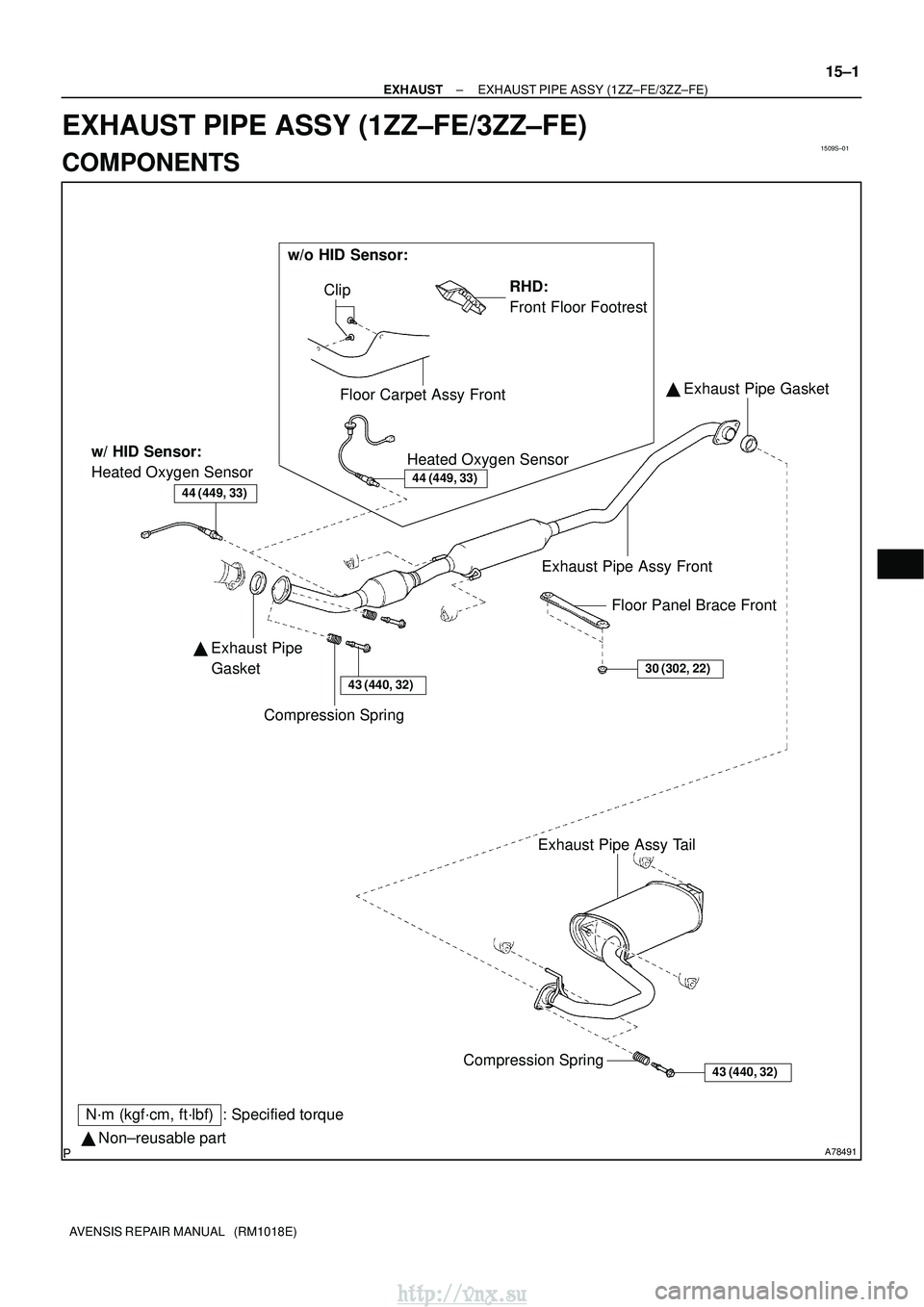
1509S±01
A78491� Non±reusable part
N´m (kgf´cm, ft´lbf) : Specified torque Exhaust Pipe Assy Front
Compression Spring Floor Panel Brace Front
�
Exhaust Pipe
Gasket
43 (440, 32)
� Exhaust Pipe Gasket
30 (302, 22)
43 (440, 32)Compression Spring
Exhaust Pipe Assy Tail
w/ HID Sensor:
Heated Oxygen Sensor
44 (449, 33)44 (449, 33)
RHD:
Front Floor Footrest
Clip
Floor Carpet Assy Front Heated Oxygen Sensor
w/o HID Sensor:
±
EXHAUST EXHAUST PIPE ASSY (1ZZ±FE/3ZZ±FE)
15±1
AVENSIS REPAIR MANUAL (RM1018E)
EXHAUST PIPE ASSY (1ZZ±FE/3ZZ±FE)
COMPONENTS
http://vnx.su
Page 742 of 2234
1509T±01
A78493
A78494
(c)
(d)
A78495
A78496
15±2
±
EXHAUSTEXHAUST PIPE ASSY(1ZZ±FE/3ZZ±FE)
AVENSIS REPAIR MANUAL (RM1018E)
Removal & Installation and Disassembly & Reassembly
1.REMOVE FRONT FLOOR FOOTREST (W/O HID SENSOR) (See page 76±32) 2. REMOVE HEATED OXYGEN SENSOR (W/O HIDSENSOR)
(a) Using a clip remover, remove the 2 clips.
(b) Open the floor carpet.
(c) Disconnect the heated oxygen sensor connector.
(d) Remove the grommet.
(e) Remove the heated oxygen sensor.
3. REMOVE HEATED OXYGEN SENSOR (W/ HID SENSOR)
(a) Disconnect the heated oxygen sensor connector.
(b) Remove the heated oxygen sensor.
http://vnx.su
Page 745 of 2234
A77857
A78440
New Gasket
±
EXHAUST EXHAUST PIPE ASSY (1ZZ±FE/3ZZ±FE)
15±5
AVENSIS REPAIR MANUAL (RM1018E)
8. INSTALL EXHAUST PIPE ASSY TAIL
(a) Compression spring inspection
(1) Using vernier calipers, measure the free length of
the compression spring.
Minimum length: 38.5 mm (1.516 in.)
If the free length is less than minimum, replace the compression
spring.
(b) Install a new gasket to the exhaust pipe front as shown in the illustration.
(c) Install the exhaust pipe tail to the 3 exhaust pipe supports.
(d) Tighten the 2 compression springs and 2 bolts. Torque: 43 N �m (440 kgf� cm, 32 ft�lbf)
9. INSTALL HEATED OXYGEN SENSOR (W/O HID SENSOR) Torque: 44 N �m (449 kgf� cm, 33 ft�lbf)
10. INSTALL HEATED OXYGEN SENSOR (W/ HID SENSOR) Torque: 44 N �m (449 kgf� cm, 33 ft�lbf)
11. CHECK FOR EXHAUST GAS LEAKS
12. INSTALL FLOOR PANEL BRACE FRONT
Torque: 30 N �m (302 kgf� cm, 22 ft�lbf)
13. INSTALL FRONT FLOOR FOOTREST (W/O HID SENSOR)
http://vnx.su
Page 802 of 2234

01±9
1ZZ±FE,3ZZ±FE ENGINE REPAIR MANUAL
(RM923E)Abbreviations Meaning
ICIntegrated Circuit
IDIIndirect Diesel Injection
IFSIndependent Front Suspension
IGIgn")
±
INTRODUCTION TERMS (1ZZ±FE/3ZZ±FE)
01±9
1ZZ±FE,3ZZ±FE ENGINE REPAIR MANUAL
(RM923E)Abbreviations Meaning
ICIntegrated Circuit
IDIIndirect Diesel Injection
IFSIndependent Front Suspension
IGIgnition
IIAIntegrated Ignition Assembly
INIntake (Manifold, Valve)
INTIntermittent
I/PInstrument Panel
IRSIndependent Rear Suspension
ISCIdle Speed Control
J/BJunction Block
J/CJunction Connector
KDKick±Down
LANLocal Area Network
LBLiftback
LCDLiquid Crystal Display
LEDLight Emitting Diode
LHLeft±Hand
LHDLeft±Hand Drive
L/H/WLength, Height, Width
LLCLong±Life Coolant
LNGLiquified Natural Gas
LOLow
LPGLiquified Petroleum Gas
LSDLimited Slip Differential
LSP & PVLoad Sensing Proportioning And Bypass Valve
LSPVLoad Sensing Proportioning Valve
MAPManifold Absolute Pressure
MAX.Maximum
MICMicrophone
MILMalfunction Indicator Lamp
MIN.Minimum
MPMultipurpose
MPIMultipoint Electronic Injection
MPXMultiplex Communication System
M/TManual Transmission
MTMount
MTGMounting
NNeutral
NANatural Aspiration
NO.Number
O2SOxygen Sensor
O/DOverdrive
OEMOriginal Equipment Manufacturing
OHCOverhead Camshaft
OHVOverhead Valve
OPTOption
O/SOversize
P & BVProportioning And Bypass Valve
PCSPower Control System
PCVPositive Crankcase Ventilation
http://vnx.su

14±37
AVENSIS REPAIR MANUAL (RM1018E)
85. REMOVE EXHAUST MANIFOLD HEAT INSULATOR
NO.1
(a) Disconnect t")

(d)
A78495
A78496
15±2
±
EXHAUSTEXHAUST PIPE ASSY(1ZZ±FE/3ZZ±FE)
AVENSIS REPAIR MANUAL (RM1018E)
Removal & Installation and Disassembly & Reassembly
1.REMOVE FRONT FL")

15±5
AVENSIS REPAIR MANUAL (RM1018E)
8. INSTALL EXHAUST PIPE ASSY TAIL
(a) Compression spring inspection
(1) Using vernier ca")