Page 1238 of 2234

PROBLEM SYMPTOMS TABLE
HINT:
Use the table below to help you find the cause of the problem. The numbers \
indicate")
5000D±14
50±2
±
STEERING COLUMN STEERING SYSTEM
AVENSIS REPAIR MANUAL (RM1018E)
PROBLEM SYMPTOMS TABLE
HINT:
Use the table below to help you find the cause of the problem. The numbers \
indicate the likelihood of the
cause in the descending order. Check each part in the order shown. Repair or replace these parts as n\
eces-
sary.
Oil pressure power steering:
SymptomSuspect AreaSee page
Hard steering
11. Tires (Improperly inflated)
12.Power steering fluid level (Low)
13.Drive belt (Loose)
14.Front wheel alignment (Incorrect)
15.Steering system joints (Worn)
16.Suspension arm ball joints (Worn)
17.Steering column (Binding)
18.Power steering vane pump
19.Power steering gear28±1
51±4
51±4
26±6 ±
26±24 ±
51±9
51±19
51±36
Poor return
1. Tires (Improperly inflated)
2. Front wheel alignment (Incorrect)
3. Steering column (Binding)
4. Power steering gear28±1
26±6 ±
51±36
Excessive play
1. Steering system joints (Worn)
2. Suspension arm ball joints (Worn)
3. Intermediate shaft, Sliding yoke (Worn)
4. Front wheel bearing (Worn)
5. Power steering gear±
26±24 ±
30±22
51±36
Abnormal noise
1. Power steering fluid level (Low)
2. Steering system joints (Worn)
3. Power steering vane pump
4. Power steering gear51±4 ±
51±9
51±19
51±36
http://vnx.su
Page 1245 of 2234

or less
±
POWER STEERING POWER STEERING SYSTEM
51±5
AVENSIS REPAIR MANUAL (RM1018E)
(c) Start the engine and run it at idle.")
R11229
NormalAbnormal
R11786Engine Idling Engine Stopped5 mm (0.20 in.)
or less
±
POWER STEERING POWER STEERING SYSTEM
51±5
AVENSIS REPAIR MANUAL (RM1018E)
(c) Start the engine and run it at idle.
(d) Turn the steering wheel from lock to lock several times to
boost fluid temperature.
Fluid temperature: 80� C (176�F)
(e) Check for foaming or emulsification.
If there is foaming or emulsification, bleed the power steering
system.
(f) With the engine idling, measure the fluid level in the oil reservoir.
(g) Stop the engine.
(h) Wait a few minutes and remeasure the fluid level in the oil reservoir.
Maximum fluid level rise: 5 mm (0.20 in.)
If a problem is found, bleed power steering system.
(i) Check the fluid level.
4. CHECK STEERING FLUID PRESSURE
(a) AZ Series: Disconnect the pressure feed tube assy from the vane
pump assy (See page 51±9).
(b) 1CD±FTV: Disconnect the pressure feed tube assy from the vane
pump assy (See page 51±19).
(c) AZ Series: Connect SST(s), as shown in the illustration on the next
page.
SST 09640±10010 (09641±01010, 09641±01030, 09641±01060)
NOTICE:
Check that the valve of SST(s) is in the open position.
(d) 1CD±FTV: Connect SST(s), as shown in the illustration on the next
page.
SST 09640±10010 (09641±01010, 09641±01020, 09641±01030)
NOTICE:
Check that the valve of SST(s) is in the open position.
(e) Bleed the power steering system.
(f) Start the engine and run it at idle.
(g) Turn the steering wheel from lock to lock several times to
boost fluid temperature.
Fluid temperature: 80 �C (176 �F)
http://vnx.su
Page 1246 of 2234
D30364
AttachmentOUT
IN
IN OUTAttachment
SST(s)
SST(s)
Attachment
Attachment
AZ Series:
1CD±FTV:
Z15498
Oil
Reservoir
PS Vane
Pump
PS Gear
SST(s)
Closed
Z15499
Oil
Reservoir
PS Vane
Pump
PS Gear
SST(s)
Open
51±6
±
POWER STEERING POWER STEERING SYSTEM
AVENSIS REPAIR MANUAL (RM1018E)
(h) With the engine idling, close the valve of SST(s) and ob- serve the reading on SST(s).
Minimum fluid pressure:
AZ Series:
8,300 to 9,000 kPa (85 to 92 kgf/cm
2, 1,204 to 1,305 psi)
1CD±FTV:
8,800 to 9,500 kPa (90 to 97 kgf/cm
2, 1,276 to 1,378 psi)
NOTICE:
�Do not keep the valve closed for more than 10 se-
conds.
�Do not let the fluid temperature become too high.
(i) With the engine idling, open the valve fully.
(j) Measure the fluid pressure at engine speeds of 1,000 rpm and 3,000 rpm.
Fluid pressure difference:
490 kPa (5 kgf/cm
2, 71 psi) or less
NOTICE:
Do not turn the steering wheel.
http://vnx.su
Page 1247 of 2234

Open
Lock Position
F08858
±
POWER STEERING POWER STEERING SYSTEM
51±7
AVENSIS REPAIR MANUAL (RM1018E)
(k) With the engine idling and valve fully ope")
Z15500
Oil
ReservoirPS Vane
Pump
PS Gear
SST(s)
Open
Lock Position
F08858
±
POWER STEERING POWER STEERING SYSTEM
51±7
AVENSIS REPAIR MANUAL (RM1018E)
(k) With the engine idling and valve fully opened, turn the
steering wheel to full lock position.
Minimum fluid pressure:
AZ Series:
8,300 to 9,000 kPa (85 to 92 kgf/cm
2, 1,204 to 1,305 psi)
1CD±FTV:
8,800 to 9,500 kPa (90 to 97 kgf/cm
2, 1,276 to 1,378 psi)
NOTICE:
�Do not maintain lock position for more than 10 se-
conds.
�Do not let the fluid temperature become too high.
(l) Remove SST(s).
(m) AZ Series:
Connect the pressure feed tube assy to the vane pump
assy (See page 51±9).
(n) 1CD±FTV:
Connect the pressure feed tube assy to the vane pump
assy (See page 51±19).
(o) Bleed the power steering system.
5. CHECK STEERING EFFORT
(a) Center the steering wheel.
(b)Remove the steering wheel pad (See page 60±17).
(c) Start the engine and run it at idle.
(d) Measure the steering effort in both directions. Steering effort (Reference):
5.5 N´m (56 kgf´cm, 49 in.´lbf)
HINT:
Take the tire type, pressure and contact surface into consider-
ation before making your diagnosis.
(e) Torque the steering wheel set nut. Torque: 50 N´m (510 kgf´cm, 37 ft´lbf)
(f)Install the steering wheel pad (See page 60±17).
http://vnx.su
Page 1267 of 2234
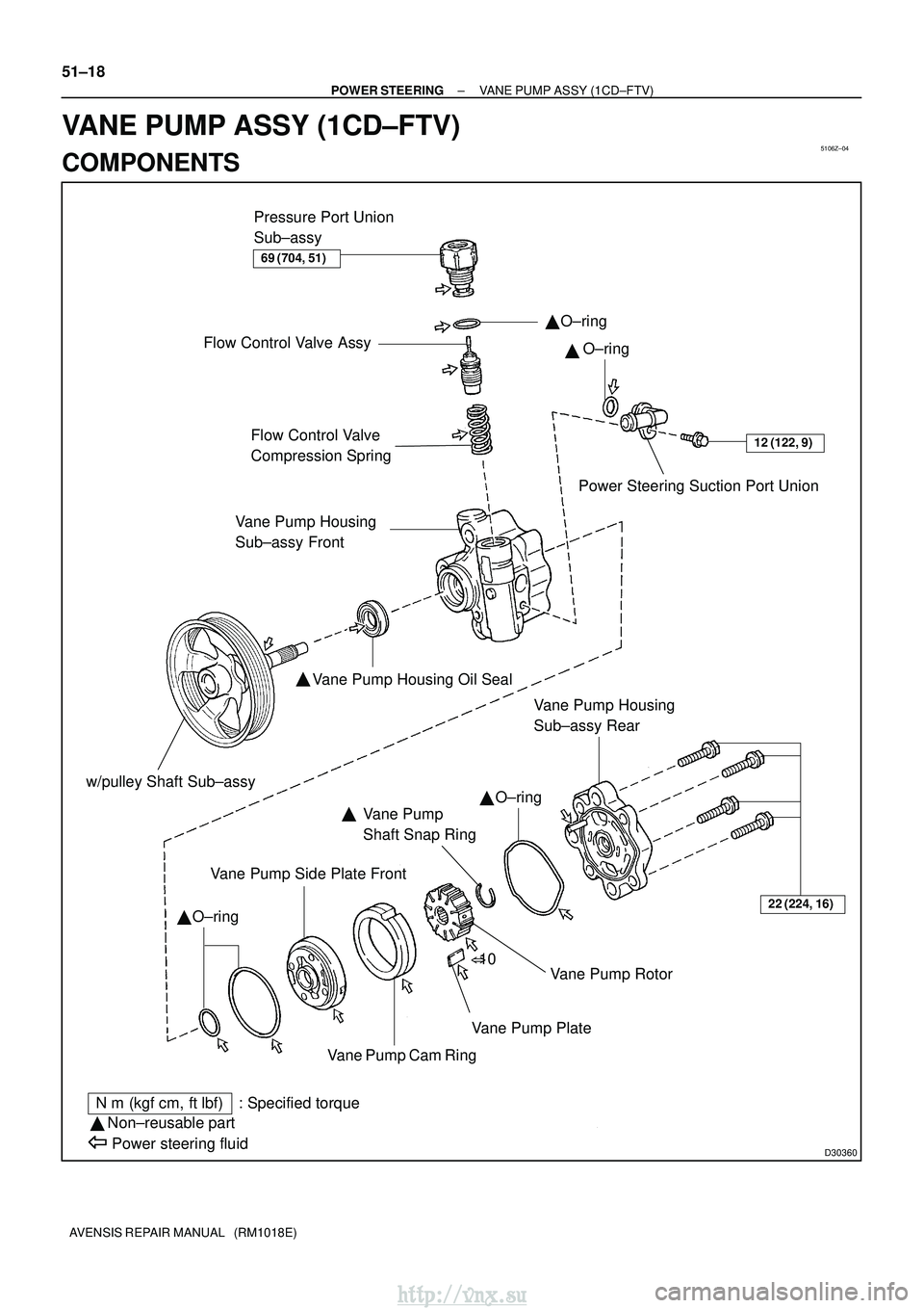
5106Z±04
D30360
�
12 (122, 9)Flow Control Valve
Compression SpringPower Steering Suction Port Union
Vane Pump Housing Oil Seal
�
Vane Pump
Shaft Snap Ring
Vane Pump Side Plate Front
Vane Pump Rotor
Vane Pump Plate
Vane Pump Cam Ring
N �m (kgf� cm, ft�lbf) : Specified torque
� Non±reusable part
Power steering fluid
�
�
�
22 (224, 16)
� 10
Pressure Port Union
Sub±assy
Flow Control Valve Assy
Vane Pump Housing
Sub±assy Front
�
Vane Pump Housing
Sub±assy Rear
69 (704, 51)
O±ringO±ring
O±ring
O±ring
w/pulley Shaft Sub±assy
51±18
±
POWER STEERING VANE PUMP ASSY (1CD±FTV)
AVENSIS REPAIR MANUAL (RM1018E)
VANE PUMP ASSY (1CD±FTV)
COMPONENTS
http://vnx.su
Page 1268 of 2234

D30580
C84636
SST(s)
±
POWER STEERING VANE PUMP ASSY (1CD±FTV)
51±19
AVENSIS REPAIR MANUAL (RM1018E)
OVERHAUL
NOTICE:
�When using a vise, do not overtighten.
�When installi")
510DH±02
D30579SST(s)
D30580
C84636
SST(s)
±
POWER STEERING VANE PUMP ASSY (1CD±FTV)
51±19
AVENSIS REPAIR MANUAL (RM1018E)
OVERHAUL
NOTICE:
�When using a vise, do not overtighten.
�When installing, coat the parts indicated by the arrows with power steer\
ing fluid
(See page 51±18).
1. REMOVE V (COOLER COMPRESSOR TO CRANKSHAFT PULLEY) BELT NO.1 (See page 55±46)
2. REMOVE ENGINE COVER NO.1
(a) Remove the bolt, 4 nuts and the engine cover No. 1.
3. DISCONNECT OIL RESERVOIR TO PUMP HOSE NO.1
(a) Remove the clip and disconnect the oil reservoir to pump hose No. 1.
NOTICE:
Take care not to spill fluid on the V belt.
4. DISCONNECT PRESSURE FEED TUBE ASSY
(a) Remove the bolt and sepatate the tube clamp.
(b) Using SST(s), disconnect the pressure feed tube assyfrom the vane pump assy.
SST 09023±12700
5. REMOVE VANE PUMP ASSY
(a) Remove the 4 bolts, the vane pump assy and the vane pump bracket rear.
6. FIX VANE PUMP ASSY
(a) Using SST(s), hold the vane pump assy in a vise. SST 09630±00014 (09631±00132)
7. REMOVE POWER STEERING SUCTION PORT UNION
(a) Remove the bolt and the suction port union.
(b) Remove the O±ring from the suction port union.
http://vnx.su
Page 1272 of 2234
Oil Seal
������D30334
Vinyl Tape
±
POWER STEERING VANE PUMP ASSY (1CD±FTV)
51±23
AVENSIS REPAIR MANUAL (RM1018E)
If necessary, replace t")
D31004
Inscribed Mark
R08702
Vernier Calipers
F42121
SST(s)Oil Seal
������D30334
Vinyl Tape
±
POWER STEERING VANE PUMP ASSY (1CD±FTV)
51±23
AVENSIS REPAIR MANUAL (RM1018E)
If necessary, replace the flow control valve assy with the one
having the same letter as inscribed on the housing sub±assy
front
Inscribed mark: A, B, C, D, E or F
HINT:
There are 6 different marks for flow control valve assy.
MarkPart number
A44330±05190
B44330±05200
C44330±05210
D44330±05220
E44330±05230
F44330±05240
18. INSPECT FLOW CONTROL VALVE COMPRESSION SPRING
(a) Using vernier calipers, measure the free length of the compression spring.
Minimum free length: 36.9 mm ( 1.453 in.)
If it is less than the minimum, replace the compression spring.
19. INSPECT PRESSURE PORT UNION SUB±ASSY
(a) If the union seat in the pressure port union sub±assy is remarkably damaged, it may cause flui\
d leak- age. Replace the pressure port union sub±assy.
20. INSTALL VANE PUMP HOUSING OIL SEAL
(a) Coat a new housing oil seal lip with power steering fluid.
(b) Using SST(s) and a press, install a new housing oil seal.SST 09950±60010 (09951±00280), 09950±70010
(09951±07100)
NOTICE:
Make sure that the oil seal is installed facing in the correct
direction.
21. INSTALL W/PULLEY SHAFT SUB±ASSY
(a) Coat inside bushing surface of the housing sub±assy front with power steering fluid.
(b) Gradually insert the w/pulley shaft sub±assy.
NOTICE:
Do not damage the oil seal lip.
HINT:
Tape the shaft before inserting.
http://vnx.su
Page 1275 of 2234

51±26
±
POWER STEERING VANE PUMP ASSY (1CD±FTV)
AVENSIS REPAIR MANUAL (RM1018E)
28. INSTALL FLOW CONTROL VALVE ASSY
(a) Coat the compressi")
������D30361
D30580
B
B
B
A
D30581
Fulcrum
Length
SST(s)
51±26
±
POWER STEERING VANE PUMP ASSY (1CD±FTV)
AVENSIS REPAIR MANUAL (RM1018E)
28. INSTALL FLOW CONTROL VALVE ASSY
(a) Coat the compression spring and the flow control valve assy with power steering fluid.
(b) Install the compression spring and the flow control valve assy.
(c) Coat a new O±ring with power steering fluid and install it onto the pressure port union sub±assy.
(d) Install the pressure port union sub±assy. Torque: 69 N �m (704 kgf� cm, 51 ft�lbf)
29. INSTALL POWER STEERING SUCTION PORT UNION
(a) Coat a new O±ring with power steering fluid, and install it to the su\
ction port union.
(b) Install the suction port union with the bolt. Torque: 12 N �m (122 kgf� cm, 9 ft�lbf)
30. INSTALL VANE PUMP ASSY
(a) Install the vane pump assy and vane pump bracket rear with the 4 bolts.
Torque:
Bolt A: 72 N� m (734 kgf�cm, 53 ft�lbf)
Bolt B: 39 N� m (398 kgf�cm, 29 ft�lbf)
31. CONNECT PRESSURE FEED TUBE ASSY
(a) Using SST(s), connect the pressure feed tube assy. SST 09023±12700
Torque: 41 N �m (414 kgf� cm, 30 ft�lbf)
HINT:
�Use a torque wrench with a fulcrum length of 345 mm
(13.58 in.).
�This torque value is effective when SST(s) is parallel to a
torque wrench.
(b) Install the tube clamp with the bolt. Torque: 8.0 N �m (82 kgf �cm, 71 in. �lbf)
32. CONNECT OIL RESERVOIR TO PUMP HOSE NO.1
(a) Connect the oil reservoir to pump hose No. 1 with the clip.
NOTICE:
Take care not to spill fluid on the V belt.
33. INSTALL V (COOLER COMPRESSOR TO CRANKSHAFT PULLEY) BELT NO.1 (See page 55±46)
34. ADJUST V (COOLER COMPRESSOR TO CRANKSHAFT PULLEY) BELT NO.1
(See page 55±46)
35.ADD POWER STEERING FLUID (See page 51±4)
36.BLEED POWER STEERING FLUID (See page 51±4)
37.CHECK POWER STEERING FULUID LEVEL IN RESERVER (See page 51±4)
38. INSPECT FLUID LEAK
http://vnx.su

SST(s)
Attachment
Attachment
AZ Series:
1CD±FTV:
Z15498
Oil
Reservoir
PS Vane
Pump
PS Gear
SST(s)
Closed
Z15499
Oil
Reservoir
PS Vane
Pump
PS Gear
SST(")