Page 1276 of 2234
510DF±02
F42473
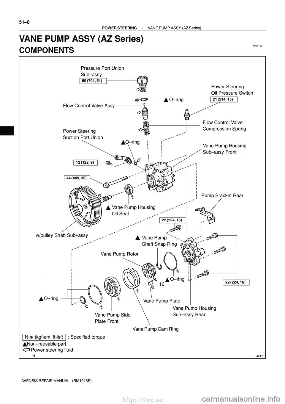
Power Steering
Suction Port UnionO±ring
�
w/pulley Shaft Sub±assy Vane Pump Side
Plate FrontVane Pump Cam Ring�
10
�
N�m (kgf� cm, ft�lbf) : Specified torque
Non±reusable part
�
Power steering fluid
Pump Bracket Rear
Flow Control Valve Assy
�
Flow Control Valve
Compression Spring
44 (449, 32)
Vane Pump Housing
Sub±assy Rear Vane Pump Housing
Sub±assy Front
�
Vane Pump Rotor
Vane Pump Plate
22 (224, 16)
Vane Pump Housing
Oil Seal
�
Power Steering
Oil Pressure Switch
21 (214, 15)
69 (704, 51)
Vane Pump
Shaft Snap Ring
� O±ring
O±ring
O±ring
22 (224, 16)
Pressure Port Union
Sub±assy
12 (122, 9)
51±8
±
POWER STEERING VANE PUMP ASSY (AZ Series)
AVENSIS REPAIR MANUAL (RM1018E)
VANE PUMP ASSY (AZ Series)
COMPONENTS
http://vnx.su
Page 1277 of 2234

A
B
F40247
SST(s)
±
POWER STEERING VANE PUMP ASSY (AZ Series)
51±9
AVENSIS REPAIR MANUAL (RM1018E)
OVERHAUL
NOTICE:
�When using a vise, do not over tighten")
510DG±02
F40529
Turn
Hold
D30330
SST(s)
A
B
F40247
SST(s)
±
POWER STEERING VANE PUMP ASSY (AZ Series)
51±9
AVENSIS REPAIR MANUAL (RM1018E)
OVERHAUL
NOTICE:
�When using a vise, do not over tighten.
�When installing, coat the parts indicated by the arrows with power steer\
ing fluid
(See page 51±8).
1. REMOVE FRONT WHEEL RH
2. REMOVE ENGINE UNDER COVER RH
3. REMOVE FAN AND GENERATOR V BELT 1AZ±FE: (See page 14±105)
1AZ±FSE: (See page 14±185)
4. DISCONNECT OIL RESERVOIR TO PUMP HOSE NO.1
(a) Remove the clip and disconnect the oil reservoir to pump hose No.1.
NOTICE:
Take care not to spill fluid on the V belt.
5. DISCONNECT PRESSURE FEED TUBE ASSY
(a) Remove the bolt and separate the pressure feed tubeassy from the pump bracket rear.
(b) Using a spanner (27 mm) to hold the pressure port union, remove the union bolt and gasket.
6. REMOVE VANE PUMP ASSY
(a) Disconnect the connector from the oil pressure switch.
(b) Using SST(s) and a deep socket (14 mm), loosen the bolt A.
SST 09249±63010
(c) Remove the bolt B and vane pump assy.
7. FIX VANE PUMP ASSY
(a) Using SST(s), hold the vane pump assy in a vise. SST 09630±00014 (09631±00132)
8. REMOVE PUMP BRACKET REAR
(a) Remove the bolt and vane pump bracket rear.
http://vnx.su
Page 1278 of 2234

AVENSIS REPAIR MANUAL (RM1018E)
9. REMOVE POWER STEERING SUCTION PORT UNION
(a) Remove the bolt and the suction port union.
(")
F42475
C84483
C57767
51±10
±
POWER STEERING VANE PUMP ASSY (AZ Series)
AVENSIS REPAIR MANUAL (RM1018E)
9. REMOVE POWER STEERING SUCTION PORT UNION
(a) Remove the bolt and the suction port union.
(b) Remove the O±ring from the suction port union. 10. REMOVE FLOW CONTROL VALVE ASSY
(a) Remove the pressure port union sub±assy.
(b) Remove the O±ring from the pressure port union sub±assy.
(c) Remove the flow control valve assy and the compression spring.
11. REMOVE POWER STEERING OIL PRESSURE SWITCH
NOTICE:
If the oil pressure switch is dropped or damaged, replace it with a new \
one. 12. REMOVE VANE PUMP HOUSING SUB±ASSY REAR
(a) Remove the 4 bolts and housing sub±assy rear from thehousing sub±assy front.
(b) Remove the O±ring from the housing sub±assy rear.
13. REMOVE W/PULLEY SHAFT SUB±ASSY
(a) Using 2 screwdrivers, remove the snap ring from the w/ pulley shaft sub±assy.
(b) Remove the w/pulley shaft sub±assy.
14. REMOVE VANE PUMP ROTOR
(a) Remove the 10 vane pump plates.
(b) Remove the vane pump rotor.
15. REMOVE VANE PUMP CAM RING
http://vnx.su
Page 1281 of 2234

Oil Seal
������D30334
Vinyl Tape
±
POWER STEERING VANE PUMP ASSY (AZ Series)
51±13
AVENSIS REPAIR MANUAL (RM1018E)
If necessary, replace")
D31004
Inscribed Mark
R08702
Vernier Calipers
F08480
SST(s)
Oil Seal
������D30334
Vinyl Tape
±
POWER STEERING VANE PUMP ASSY (AZ Series)
51±13
AVENSIS REPAIR MANUAL (RM1018E)
If necessary, replace the flow control valve assy with the one
having the same letter as inscribed on the housing sub±assy
front.
Inscribed mark: A, B, C, D, E or F
HINT:
There are 6 different marks for flow control valve assy.
MarkPart number
A44330±05130
B44330±05140
C44330±05150
D44330±05160
E44330±05170
F44330±05180
21. INSPECT FLOW CONTROL VALVE COMPRESSION SPRING
(a) Using vernier calipers, measure the free length of the compression spring.
Minimum free length: 36.9 mm ( 1.453 in.)
If it is less than the minimum, replace the compression spring.
22. INSPECT PRESSURE PORT UNION SUB±ASSY
(a) If the union seat in the pressure port union sub±assy is remarkably damaged, it may cause flui\
d leak- age. Replace the pressure port union sub±assy.
23. INSTALL VANE PUMP HOUSING OIL SEAL
(a) Coat a new housing oil seal lip with power steering fluid.
(b) Using SST(s) and a press, install a new housing oil seal.SST 09950±60010 (09951±00280), 09950±70010
(09951±07100)
NOTICE:
Make sure that the oil seal is installed facing in the correct
direction.
24. INSTALL W/PULLEY SHAFT SUB±ASSY
(a) Coat inside bushing surface of the housing sub±assy front with power steering fluid.
(b) Gradually insert the w/pulley shaft sub±assy.
NOTICE:
Do not damage the oil seal lip.
HINT:
Tape the shaft before inserting.
http://vnx.su
Page 1283 of 2234

51±15
AVENSIS REPAIR MANUAL (RM1018E)
(b) Coat 10 vane pump plates with power steeri")
������D30335
Inward
Outward
������D30336
C70126
C53369
Service Bolt
±
POWER STEERING VANE PUMP ASSY (AZ Series)
51±15
AVENSIS REPAIR MANUAL (RM1018E)
(b) Coat 10 vane pump plates with power steering fluid.
(c) Install the vane pump plates with the round end facing
outward.
28. INSTALL VANE PUMP SHAFT SNAP RING
(a) Using a screwdriver and a snap ring expander, install a new snap ring to the w/pulley shaft sub±assy.
29. INSTALL VANE PUMP HOUSING SUB±ASSY REAR
(a) Coat a new O±ring with power steering fluid and install it onto the housing sub±assy rear.
(b) Align the straight pin of the housing sub±assy rear with the dents of the cam ring, side plate front and housing
sub±assy front, and install the vane pump housing sub±
assy rear with the 4 bolts.
Torque: 22 N �m (224 kgf� cm, 16 ft�lbf)
30. INSPECT PRELOAD
(a) Check that the pump rotates smoothly without abnormal noise.
(b) Temporarily install the service bolt.
Recommended service bolt:
Thread diameter: 10 mm (0.39 in.)
Thread pitch: 1.25 mm (0.0492 in.)
Bolt length: 50 mm (1.97 in.)
(c) Using a torque wrench, check the pump rotating torque. Rotating torque:
0.27 N� m (2.8 kgf �cm, 2.4 ft� lbf) or less
If the rotating torque is not as specified, check the housing oil
seal.
31. INSTALL POWER STEERING OIL PRESSURE SWITCH
(a) Coat a new O±ring with power steering fluid and install it to the oil\
pressure switch.
(b) Install the oil pressure switch onto the vane pump assy. Torque: 21 N �m (214 kgf� cm, 15 ft�lbf)
http://vnx.su
Page 1284 of 2234

BFulcrum Length
F41596
Pressure Feed
Tube Assy
Stopper
51±16
±
POWER STEERING VANE PUMP ASSY (AZ Series)
AVENSIS REPAIR MANUAL (RM1018E)
32. INSTALL FLOW CONTROL VALVE ASSY")
F42475
F40330
A
SST(s)
BFulcrum Length
F41596
Pressure Feed
Tube Assy
Stopper
51±16
±
POWER STEERING VANE PUMP ASSY (AZ Series)
AVENSIS REPAIR MANUAL (RM1018E)
32. INSTALL FLOW CONTROL VALVE ASSY
(a) Coat the compression spring and the flow control valve assy with power steering fluid.
(b) Install the compression spring and the flow control valve assy.
(c) Coat a new O±ring with power steering fluid and install it onto the pressure port union sub±assy.
(d) Install the pressure port union sub±assy. Torque: 69 N �m (704 kgf� cm, 51 ft�lbf)
33. INSTALL POWER STEERING SUCTION PORT UNION
(a) Coat a new O±ring with power steering fluid, and install it to the su\
ction port union.
(b) Install the suction port union with the bolt. Torque: 12 N �m (122 kgf� cm, 9 ft�lbf)
34. INSTALL PUMP BRACKET REAR
(a) Install the vane pump bracket rear with the bolt. Torque: 44 N �m (449 kgf� cm, 32 ft�lbf)
HINT:
Make sure that the stopper of the bracket touches the vane pump body, then torque the bolt.
35. INSTALL VANE PUMP ASSY
(a) Temporarily tighten the bolt A to the vane pump assy.
(b) Install the vane pump assy and the bolt B.Torque: 37 N �m (377 kgf� cm, 27 ft�lbf)
(c) Using SST(s) and a deep socket (14 mm), tighten the bolt
A.
SST 09249±63010
Torque: 26 N� m (264 kgf�cm, 19 ft�lbf)
HINT:
�Use a torque wrench with a fulcrum length of 345 mm
(13.58 in.).
�This torque value is effective when SST(s) is parallel to a
torque wrench.
(d) Connect the connector to the oil pressure switch.
36. CONNECT PRESSURE FEED TUBE ASSY
(a) Install the pressure feed tube assy and gasket to the vane pump assy with the union bolt.
HINT:
Make sure the stopper of the pressure feed tube assy touches
the pump housing front as shown in the illustration.
(b) Using a spanner (27 mm) to hold the pressure port union, torque the union bolt.
Torque: 52 N �m (525 kgf� cm, 38 ft�lbf)
(c) Install the pressure feed tube assy with bolt to the pump bracket rear.
Torque: 8.0 N �m (82 kgf �cm, 71 in. �lbf)
http://vnx.su
Page 1293 of 2234

AIR CONDITIONING SYSTEM
PRECAUTION
1. DO NOT HANDLE REF")
5507E±03
AC2810
AC2811
N11084
Wrong Okay
HI
LO
HILO
±
HEATER & AIR CONDITIONER AIR CONDITIONING SYSTEM
55±1
AVENSIS REPAIR MANUAL (RM1018E)
AIR CONDITIONING SYSTEM
PRECAUTION
1. DO NOT HANDLE REFRIGERANT IN AN ENCLOSED
AREA OR NEAR AN OPEN FLAME
2. ALWAYS WEAR EYE PROTECTION
3. BE CAREFUL NOT TO GET LIQUID REFRIGERANT IN YOUR EYES OR ON YOUR SKIN
If liquid refrigerant gets in your eyes or on your skin.
(a) Wash the area with lots of cold water.
CAUTION:
Do not rub your eyes or skin.
(b) Apply clean petroleum jelly to the skin.
(c) Go immediately to a hospital or see a physician for profes- sional treatment.
4. NEVER HEAT CONTAINER OR EXPOSE IT TO NAKED
FLAME
5. BE CAREFUL NOT TO DROP CONTAINER AND NOT TO APPLY PHYSICAL SHOCKS TO IT
6. DO NOT OPERATE COMPRESSOR WITHOUT ENOUGH REFRIGERANT IN REFRIGERANT SYSTEM
If there is not enough refrigerant in the refrigerant system, oil lu-
brication will be insufficient and compressor may burnout may
occur, so take care to avoid this, necessary care should be tak-
en.
7. DO NOT OPEN HIGH PRESSURE MANIFOLD VALVE WHILE COMPRESSOR IS OPERATING
Open and close the only low pressure valve. If the high pressure
valves are opened, refrigerant flows in the reverse direction and
cause the charging cylinder to rupture.
8. BE CAREFUL NOT TO OVERCHARGE SYSTEM WITH REFRIGERANT
If refrigerant is overcharged, it causes problems such as insuffi-
cient cooling, poor fuel economy, engine overheating, etc.
http://vnx.su
Page 1330 of 2234

I22122
Condition: Air conditioning system does not function.NOTE : These gauge indica-
tions occur when the refrigera-
tion system opens and the re-
frigerant is charged without
vacuuming.
I22123
Condition: Air conditioning system does not function effectively.
±
HEATER & AIR CONDITIONER REFRIGERANT
55±29
AVENSIS REPAIR MANUAL (RM1018E)
(7) When there is air in the refrigeration system:
SymptomProbable causeDiagnosisCorrective Actions
� Pressure is extreamly high on
both low and the high pressure
sides
� The low pressure piping is too
hot to touch
� RHD AZ engine series:
Bubbles can be seen through sight
glass
Air in refrigeration system
� There is air in refrigeration sys-
tem
� Vacuuming is insufficient
(1) Check it compressor oil is dirty
or insufficient
(2) Vacuum and supply new refrig-
erant
(8) When the expansion valve malfunctions:
SymptomProbable causeDiagnosisCorrective Actions
� Pressure is extreamly high on
both low and high pressure sides
� Frost or dew is on piping on low
pressure side
Trouble with expansion valve
� Excessive refrigerant in low
pressure piping
� Expansion valve opened too
wide
Replace expansion valve
http://vnx.su