Page 927 of 2234
170FX±01
A77339
±
LUBRICATIONOIL PUMP ASSY(1AZ±FSE)
17±15
AVENSIS REPAIR MANUAL (RM1018E)
OIL PUMP ASSY(1AZ±FSE)
REPLACEMENT
1.DISCHARGE FUEL SYSTEM PRESSURE (See page 11±30)
2.REMOVE FRONT WHEEL RH
3.REMOVE RADIATOR SUPPORT OPENING COVER
4.REMOVE ENGINE ROOM COVER SIDE
5.REMOVE ENGINE UNDER COVER RH
6.REMOVE ENGINE UNDER COVER LH
7.DRAIN ENGINE OIL
(a)Install a new gasket and drain plug after draining engine oil.
Torque: 25 N �m (250 kgf�cm,18 ft�lbf)
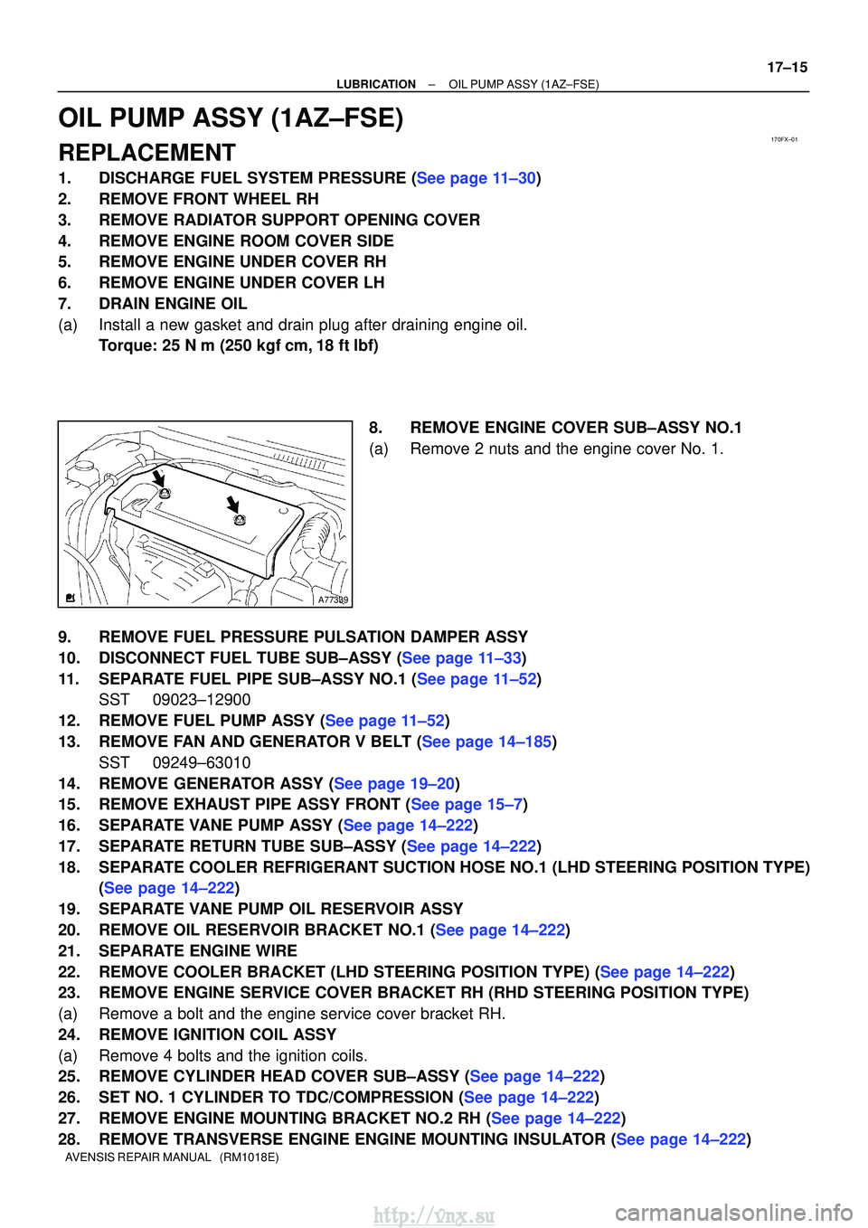
8.REMOVE ENGINE COVER SUB±ASSY NO.1
(a)Remove 2 nuts and the engine cover No. 1.
9.REMOVE FUEL PRESSURE PULSATION DAMPER ASSY
10.DISCONNECT FUEL TUBE SUB±ASSY (See page 11±33)
11.SEPARATE FUEL PIPE SUB±ASSY NO.1 (See page 11±52) SST 09023±12900
12.REMOVE FUEL PUMP ASSY (See page 11±52)
13.REMOVE FAN AND GENERATOR V BELT (See page 14±185) SST 09249±63010
14.REMOVE GENERATOR ASSY (See page 19±20)
15.REMOVE EXHAUST PIPE ASSY FRONT (See page 15±7)
16.SEPARATE VANE PUMP ASSY (See page 14±222)
17.SEPARATE RETURN TUBE SUB±ASSY (See page 14±222)
18. SEPARATE COOLER REFRIGERANT SUCTION HOSE NO.1 (LHD STEERING POSITION TYPE) (See page 14±222)
19. SEPARATE VANE PUMP OIL RESERVOIR ASSY
20.REMOVE OIL RESERVOIR BRACKET NO.1 (See page 14±222)
21. SEPARATE ENGINE WIRE
22.REMOVE COOLER BRACKET (LHD STEERING POSITION TYPE) (See page 14±222)
23. REMOVE ENGINE SERVICE COVER BRACKET RH (RHD STEERING POSITION TYPE)
(a) Remove a bolt and the engine service cover bracket RH.
24. REMOVE IGNITION COIL ASSY
(a) Remove 4 bolts and the ignition coils.
25.REMOVE CYLINDER HEAD COVER SUB±ASSY (See page 14±222)
26.SET NO. 1 CYLINDER TO TDC/COMPRESSION (See page 14±222)
27.REMOVE ENGINE MOUNTING BRACKET NO.2 RH (See page 14±222)
28.REMOVE TRANSVERSE ENGINE ENGINE MOUNTING INSULATOR (See page 14±222)
http://vnx.su
Page 930 of 2234
17±18
±
LUBRICATIONOIL PUMP ASSY(1AZ±FSE)
AVENSIS REPAIR MANUAL (RM1018E)
64.INSTALL OIL RESERVOIR BRACKET NO.1 Torque: 8.0 N �m (82 kgf�cm,71 in. �lbf)
65.INSTALL COOLER REFRIGERANT SUCTION HOSE NO.1 (LHD STEERING POSITION TYPE)
Torque: 9.0 N �m (92 kgf�cm,80 in. �lbf)
66.INSTALL RETURN TUBE SUB±ASSY Torque: 8.0 N �m (82 kgf�cm,71 in. �lbf)
67.INSTALL IGNITION COIL ASSY
Torque: 9.0 N �m (92 kgf�cm,80 in. �lbf)
68.INSTALL VANE PUMP ASSY Torque: 37 N �m (377 kgf�cm,27 ft�lbf)
69.INSTALL EXHAUST PIPE ASSY FRONT (See page 15±7)
70.INSTALL GENERATOR ASSY (See page 19±20)
71.INSTALL FAN AND GENERATOR V BELT (See page 14±185) SST 09249±63010
72.INSTALL FUEL PUMP ASSY (See page 11±52)
73.INSTALL FUEL PIPE SUB±ASSY NO.1 (See page 11±52) SST 09023±12900
74.INSTALL FUEL TUBE SUB±ASSY (See page 11±33)
75.INSTALL FUEL PRESSURE PULSATION DAMPER ASSY (See page 11±52)
76. ADD ENGINE OIL
77. CHECK FOR ENGINE OIL LEAKS
78. CHECK FUEL LEAK
79. INSTALL ENGINE COVER SUB±ASSY NO.1 Torque: 7.0 N �m (71 kgf �cm, 62 in. �lbf)
80. INSTALL FRONT WHEEL RH
Torque: 103 N� m (1,050 kgf�cm, 76 ft �lbf)
http://vnx.su
Page 947 of 2234
B01301
IG0316
B02101
1.1 mm
B62019
18±10
±
IGNITION IGNITION SYSTEM (1AZ±FE)
AVENSIS REPAIR MANUAL (RM1018E)
(b) Alternative inspection: (1) Quickly accelerate the engine to 4,000 rpm 5 times.
(2) Remove the spark plug.
(3) Visually check the spark plug.
(4) If the electrode is dry...OK.
(5) If the electrode is wet...Proceed to step (C).
(6) Reinstall the spark plug.
(c) Check the spark plug for any damage on its thread and insulator.
If there is damage, replace the spark plug. Recommended spark plug:
DENSO madeSK20R11
NGK madeIFR6A11
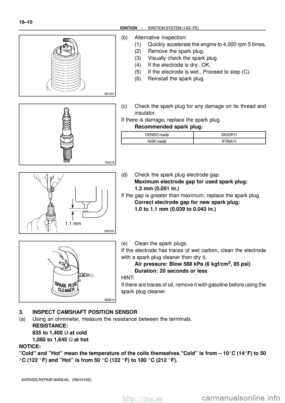
(d) Check the spark plug electrode gap.Maximum electrode gap for used spark plug:
1.3 mm (0.051 in.)
If the gap is greater than maximum, replace the spark plug. Correct electrode gap for new spark plug:
1.0 to 1.1 mm (0.039 to 0.043 in.)
(e) Clean the spark plugs.
If the electrode has traces of wet carbon, clean the electrode
with a spark plug cleaner then dry it. Air pressure: Blow 588 kPa (6 kgf/cm
2, 85 psi)
Duration: 20 seconds or less
HINT:
If there are traces of oil, remove it with gasoline before using the
spark plug cleaner.
3. INSPECT CAMSHAFT POSITION SENSOR
(a) Using an ohmmeter, measure the resistance between the terminals. RESISTANCE:
835 to 1,400 � at cold
1,060 to 1,645 �at hot
NOTICE:
ºColdº and ºHotº mean the temperature of the coils themselve\
s.ºColdº is from ± 10 �C (14� F) to 50
� C (122 �F) and ºHotº is from 50 � C (122 �F) to 100 � C (212 �F).
http://vnx.su
Page 952 of 2234
A78640
1.0 to 1.1 mm
B62019
±
IGNITION IGNITION SYSTEM (1AZ±FSE)
18±15
AVENSIS REPAIR MANUAL (RM1018E)
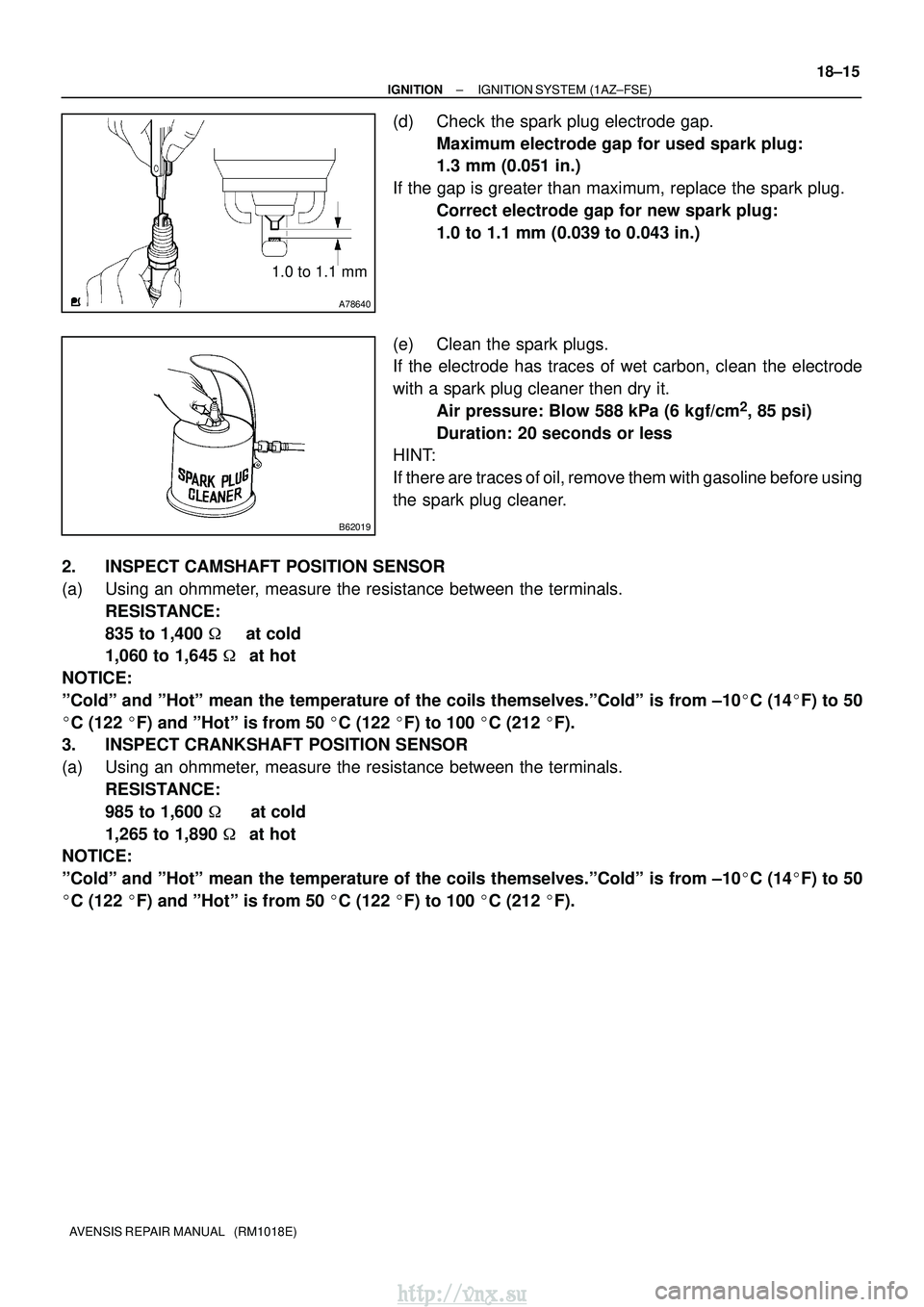
(d) Check the spark plug electrode gap.
Maximum electrode gap for used spark plug:
1.3 mm (0.051 in.)
If the gap is greater than maximum, replace the spark plug. Correct electrode gap for new spark plug:
1.0 to 1.1 mm (0.039 to 0.043 in.)
(e) Clean the spark plugs.
If the electrode has traces of wet carbon, clean the electrode
with a spark plug cleaner then dry it. Air pressure: Blow 588 kPa (6 kgf/cm
2, 85 psi)
Duration: 20 seconds or less
HINT:
If there are traces of oil, remove them with gasoline before using
the spark plug cleaner.
2. INSPECT CAMSHAFT POSITION SENSOR
(a) Using an ohmmeter, measure the resistance between the terminals. RESISTANCE:
835 to 1,400 � at cold
1,060 to 1,645 �at hot
NOTICE:
ºColdº and ºHotº mean the temperature of the coils themselves.ºColdº is\
from ±10 �C (14� F) to 50
� C (122 �F) and ºHotº is from 50 � C (122 �F) to 100 � C (212 �F).
3. INSPECT CRANKSHAFT POSITION SENSOR
(a) Using an ohmmeter, measure the resistance between the terminals.
RESISTANCE:
985 to 1,600 � at cold
1,265 to 1,890 �at hot
NOTICE:
ºColdº and ºHotº mean the temperature of the coils themselves.ºColdº is\
from ±10 �C (14� F) to 50
� C (122 �F) and ºHotº is from 50 � C (122 �F) to 100 � C (212 �F).
http://vnx.su
Page 955 of 2234
1807P±01
A50033
P03783
P03792
±
IGNITION IGNITION SYSTEM (1ZZ±FE/3ZZ±FE)
18±3
AVENSIS REPAIR MANUAL (RM1018E)
INSPECTION
1. INSPECT SPARK PLUG
(a) Clean the spark plugs.
If the electrode has traces of wet carbon, clean the electrode
with a spark plug cleaner then dry it.
Air pressure: Below 588 kPa (6kg/cm
2, 85 psi)
Duration: 20 seconds or less
(b) Check the spark plug for any damage on its thread and insulator damage.
If there is damage, replace the spark plug. Recommended spark plug:
DENSO madeK16R±U11
NGK madeBKR5EYA11
(c) Adjust electrode gap.Electrode gap: 1.0 to 1.1 mm (0.039 to 0.043 in.)
2. INSPECT CAMSHAFT POSITION SENSOR
(a) Using an ohmmeter, measure the resistance between the terminals. RESISTANCE:
835 to 1,400 � at cold
1,060 to 1,645 �at hot
NOTICE:
ºColdº and ºHotº mean the temperature of the coils themselve\
s.ºColdº is from ± 10 �C (14� F) to 50
� C (122 �F) and ºHotº is from 50 � C (122 �F) to 100 � C (212 �F).
http://vnx.su
Page 1000 of 2234
260DQ±01
F13686
C80293
26±16±
FRONT SUSPENSION FRONT SUSPENSION ARM SUB±ASSY LOWER NO.1
LH (ATM)
AVENSIS REPAIR MANUAL (RM1018E)
FRONT SUSPENSION ARM SUB±ASSY LOWER NO.1
LH (ATM)
REPLACEMENT
HINT:
�COMPONENTS: See page 26±2
�Replace the RH side (Engine: 1AZ) by the same procedures as the LH (A\
TM) side.
�Replace the RH side (Engine: 1ZZ) by the same procedures as the LH (M\
TM) side.
1. REMOVE FRONT WHEELS
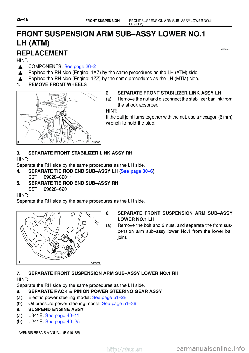
2. SEPARATE FRONT STABILIZER LINK ASSY LH
(a) Remove the nut and disconnect the stabilizer bar link fromthe shock absorber.
HINT:
If the ball joint turns together with the nut, use a hexagon (6 mm)
wrench to hold the stud.
3. SEPARATE FRONT STABILIZER LINK ASSY RH
HINT:
Separate the RH side by the same procedures as the LH side.
4.SEPARATE TIE ROD END SUB±ASSY LH (See page 30±6) SST 09628±62011
5. SEPARATE TIE ROD END SUB±ASSY RH SST 09628±62011
HINT:
Separate the RH side by the same procedures as the LH side.
6. SEPARATE FRONT SUSPENSION ARM SUB±ASSYLOWER NO.1 LH
(a) Remove the bolt and 2 nuts, and separate the front sus- pension arm sub±assy lower No.1 from the lower ball
joint.
7. SEPARATE FRONT SUSPENSION ARM SUB±ASSY LOWER NO.1 RH
HINT:
Separate the RH side by the same procedures as the LH side.
8. SEPARATE RACK & PINION POWER STEERING GEAR ASSY
(a)Electric power steering model: See page 51±28
(b)Oil pressure power steering model: See page 51±36
9. SUSPEND ENGINE ASSY
(a)U341E: See page 40±11
(b)U241E: See page 40±25
http://vnx.su
Page 1002 of 2234
C95318
C87504
C86742
AA
AAB
B
C95317
AA
A
B
26±18
±
FRONT SUSPENSIONFRONT SUSPENSION ARM SUB±ASSY LOWER NO.1
LH(ATM)
AVENSIS REPAIR MANUAL (RM1018E)
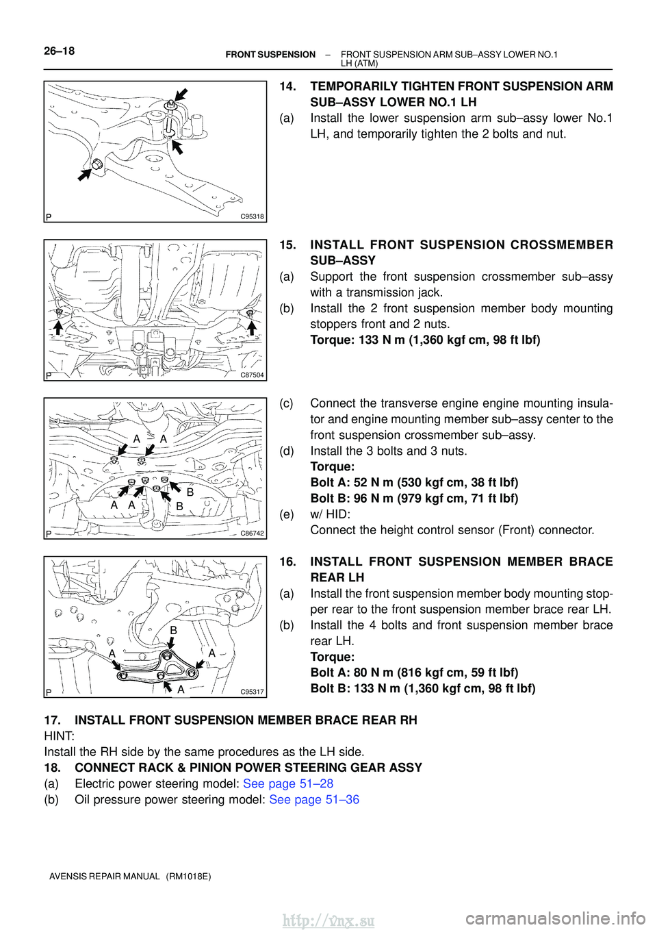
14.TEMPORARILY TIGHTEN FRONT SUSPENSION ARM SUB±ASSY LOWER NO.1 LH
(a)Install the lower suspension arm sub±assy lower No.1
LH, and temporarily tighten the 2 bolts and nut.
15.INSTALL FRONT SUSPENSION CROSSMEMBER SUB±ASSY
(a)Support the front suspension crossmember sub±assy with a transmission jack.
(b)Install the 2 front suspension member body mounting stoppers front and 2 nuts.
Torque: 133 N�m (1,360 kgf�cm, 98 ft�lbf)
(c)Connect the transverse engine engine mounting insula- tor and engine mounting member sub±assy center to the
front suspension crossmember sub±assy.
(d)Install the 3 bolts and 3 nuts. Torque:
Bolt A: 52 N�m (530 kgf�cm, 38 ft�lbf)
Bolt B: 96 N�m (979 kgf�cm, 71 ft�lbf)
(e)w/ HID: Connect the height control sensor (Front) connector.
16.INSTALL FRONT SUSPENSION ME MBER BRACE
REAR LH
(a)Install the front suspension member body mounting stop- per rear to the front suspension member brace rear LH.
(b)Install the 4 bolts and front suspension member brace rear LH.
Torque:
Bolt A: 80 N�m (816 kgf�cm, 59 ft�lbf)
Bolt B: 133 N�m (1,360 kgf �cm, 98 ft�lbf)
17.INSTALL FRONT SUSPENSION MEMBER BRACE REAR RH
HINT:
Install the RH side by the same procedures as the LH side.
18.CONNECT RACK & PINION POWER STEERING GEAR ASSY
(a)Electric power steering model: See page 51±28
(b)Oil pressure power steering model: See page 51±36
http://vnx.su
Page 1010 of 2234
SA0028
ABFront AB
A: Inside
B: Outside
Z03382
Alignment
Tester Gauge
±
FRONT SUSPENSION FRONT WHEEL ALIGNMENT
26±7
AVENSIS REPAIR MANUAL (RM1018E)
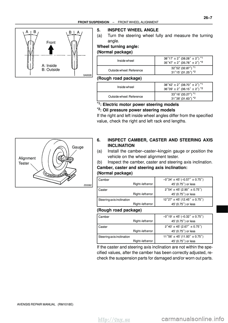
5. INSPECT WHEEL ANGLE
(a) Turn the steering wheel fully and measure the turning
angle.
Wheel turning angle:
(Normal package)
Inside wheel
� 17' � 2� �
�\b
� � \b����
� 47' � 2� �
�\f
� � \b���\b
Outside wheel: Reference32 �52' � \b�
\f����
31��5' � ��\b
���\b
(Rough road package)
Inside wheel
� 42' � 2� �
�\f�� � \b����
�� 09' � 2� � ���
� � \b���\b
Outside wheel: Reference33 �16' � �\b\f����
31�38' � ��� ���\b
*1: Electric motor power steering models
*2: Oil pressure power steering models
If the right and left inside wheel angles differ from the specified
value, check the right and left rack end lengths.
6. INSPECT CAMBER, CASTER AND STEERING AXIS INCLINATION
(a) Install the camber±caster±kingpin gauge or position the vehicle on the wheel alignment tester.
(b) Inspect the camber, caster and steering axis inclination.
Camber, caster and steering axis inclination:
(Normal package)
Camber
Right±left error±0�34' � 45' (±0.57 � � 0.75� )
45' (0.75� ) or less
Caster
Right±left error\b�54' � 45' (2.90 � � 0.75� )
45' (0.75� ) or less
Steering axis inclination
Right±left error�\b�27' � 45' (12.45 � � 0.75� )
45' (0.75� ) or less
(Rough road package)
Camber
Right±left error±0�19' � 45' (±0.32 � � 0.75� )
45' (0.75� ) or less
Caster
Right±left error\b�40' � 45' (2.67 � � 0.75� )
45' (0.75� ) or less
Steering axis inclination
Right±left error���56' � 45' (11.93 � � 0.75� )
45' (0.75� ) or less
If the caster and steering axis inclination are not within the spe-
cified values, after the camber has been correctly adjusted, re-
check the suspension parts for damaged and/or worn out parts.
http://vnx.su