Page 544 of 2234
141BB±01
A77292
A77299
14±160
±
ENGINE MECHANICAL CYLINDER HEAD GASKET (1AZ±FE)
AVENSIS REPAIR MANUAL (RM1018E)
REPLACEMENT
1.DISCHARGE FUEL SYSTEM PRESSURE (See page 11±15)
2. REMOVE FRONT WHEEL RH
3. REMOVE RADIATOR SUPPORT OPENING COVER
4. REMOVE ENGINE ROOM COVER SIDE
5. REMOVE ENGINE UNDER COVER RH
6. REMOVE ENGINE UNDER COVER LH
7.DRAIN COOLANT (See page 16±19)
8. DRAIN ENGINE OIL
(a) Install a new gasket and the drain plug after draining engine oil. Torque: 25 N �m (255 kgf� cm, 18 ft�lbf)
9.REMOVE ENGINE COVER SUB±ASSY NO.1 (See page 14±121)
10.REMOVE FAN AND GENERATOR V BELT (See page 14±105) SST 09249±63010
11.REMOVE GENERATOR ASSY (See page 19±20)
12.REMOVE EXHAUST PIPE ASSY FRONT (See page 15±7)
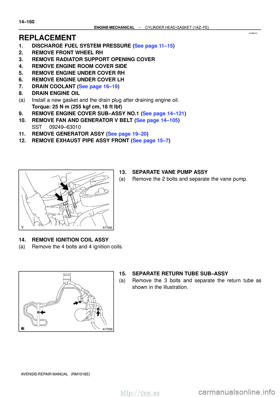
13. SEPARATE VANE PUMP ASSY
(a) Remove the 2 bolts and separate the vane pump.
14. REMOVE IGNITION COIL ASSY
(a) Remove the 4 bolts and 4 ignition coils. 15. SEPARATE RETURN TUBE SUB±ASSY
(a) Remove the 3 bolts and separate the return tube asshown in the illustration.
http://vnx.su
Page 552 of 2234
141BO±01
A77339
A77292
14±254
±
ENGINE MECHANICALCYLINDER HEAD GASKET(1AZ±FSE)
AVENSIS REPAIR MANUAL (RM1018E)
REPLACEMENT
1.DISCHARGE FUEL SYSTEM PRESSURE (See page 11±15)
2.REMOVE FRONT WHEEL RH
3.REMOVE RADIATOR SUPPORT OPENING COVER
4.REMOVE ENGINE ROOM COVER SIDE
5.REMOVE ENGINE UNDER COVER RH
6.REMOVE ENGINE UNDER COVER LH
7.DRAIN COOLANT (See page 16±19)
8.DRAIN ENGINE OIL
(a)Install a new gasket and the drain plug after draining engine oil. Torque: 25 N �m (255 kgf�cm,18 ft�lbf)
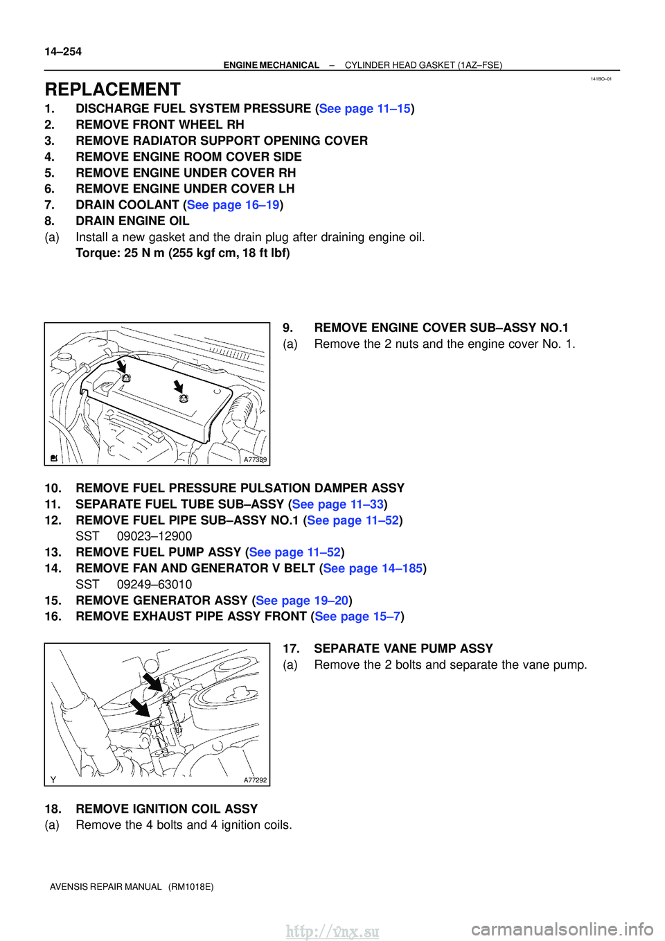
9.REMOVE ENGINE COVER SUB±ASSY NO.1
(a)Remove the 2 nuts and the engine cover No. 1.
10.REMOVE FUEL PRESSURE PULSATION DAMPER ASSY
11.SEPARATE FUEL TUBE SUB±ASSY (See page 11±33)
12.REMOVE FUEL PIPE SUB±ASSY NO.1 (See page 11±52) SST 09023±12900
13.REMOVE FUEL PUMP ASSY (See page 11±52)
14.REMOVE FAN AND GENERATOR V BELT (See page 14±185) SST 09249±63010
15.REMOVE GENERATOR ASSY (See page 19±20)
16.REMOVE EXHAUST PIPE ASSY FRONT (See page 15±7)
17. SEPARATE VANE PUMP ASSY
(a) Remove the 2 bolts and separate the vane pump.
18. REMOVE IGNITION COIL ASSY
(a) Remove the 4 bolts and 4 ignition coils.
http://vnx.su
Page 560 of 2234
14±262
±
ENGINE MECHANICAL CYLINDER HEAD GASKET (1AZ±FSE)
AVENSIS REPAIR MANUAL (RM1018E)
86.INSTALL CYLINDER HEAD COVER SUB±ASSY (See page 14±222)
87. INSTALL COOLER BRACKET (LHD STEERING POSITION TYPE) Torque: 9.0 N �m (92 kgf �cm, 80 in. �lbf)
88. INSTALL ENGINE SERVICE COVER BRACKET RH (RHD STEERING POSITION TYPE) Torque: 9.0 N �m (92 kgf �cm, 80 in. �lbf)
89. INSTALL OIL RESERVOIR BRACKET NO.1 Torque: 8.0 N �m (82 kgf �cm, 71 in. �lbf)
90. INSTALL COOLER REFRIGERANT SUCTION HOSE NO.1 (LHD STEERING POSITION TYPE)
91. INSTALL RETURN TUBE SUB±ASSY Torque: 8.0 N �m (82 kgf �cm, 71 in. �lbf)
92. INSTALL IGNITION COIL ASSY Torque: 9.0 N �m (92 kgf �cm, 80 in. �lbf)
93.INSTALL FUEL PUMP ASSY (See page 11±52)
94.INSTALL FUEL PIPE SUB±ASSY NO.1 (See page 11±52) SST 09023±12900
95.INSTALL FUEL TUBE SUB±ASSY (See page 11±33)
96.INSTALL FUEL PRESSURE PULSATION DAMPER ASSY (See page 11±52)
97. INSTALL ENGINE COVER SUB±ASSY NO.1
Torque: 7.0 N �m (71 kgf �cm, 62 in. �lbf)
98. INSTALL VANE PUMP ASSY
Torque: 37 N �m (377 kgf� cm, 27 ft�lbf)
99.INSTALL EXHAUST PIPE ASSY FRONT (See page 15±7)
100.INSTALL GENERATOR ASSY (See page 19±20)
101.INSTALL FAN AND GENERATOR V BELT (See page 14±185) SST 09249±63010
102.ADD COOLANT (See page 16±31)
103. ADD ENGINE OIL
104.CHECK FOR ENGINE COOLANT LEAKS (See page 16±25)
105. CHECK FOR ENGINE OIL LEAKS
106. CHECK FOR FUEL LEAKS
107. INSTALL FRONT WHEEL RH Torque: 103 N� m (1,050 kgf�cm, 76 ft �lbf)
http://vnx.su
Page 599 of 2234
TA C
A52006
A13304
14±102
±
ENGINE MECHANICAL ENGINE (1AZ±FE)
AVENSIS REPAIR MANUAL (RM1018E)
(5) Disconnect terminals 13 (TC) and 4 (CG) of DLC3.
(6) Inspect ignition timing at idle.
Ignition timing: 5 to 15 � BTDC
(7) Confirm that ignition timing to go advanced angle side when the engine rpm is increased.
(8) Remove the timing light.
8. INSPECT ENGINE IDLE SPEED
(a) Warm up engine.
(b) When using hand±held tester:
(1) Connect the hand±held tester to the DLC3.
Idle speed: 650 to 750 rpm
NOTICE:
�Check the idle speed with the cooling fan OFF.
�Switch off all accessories and air conditioning before
connecting the test prove to the terminal.
HINT:
Please refer to the hand±held tester operator's manual if you
need help to select DATA LIST.
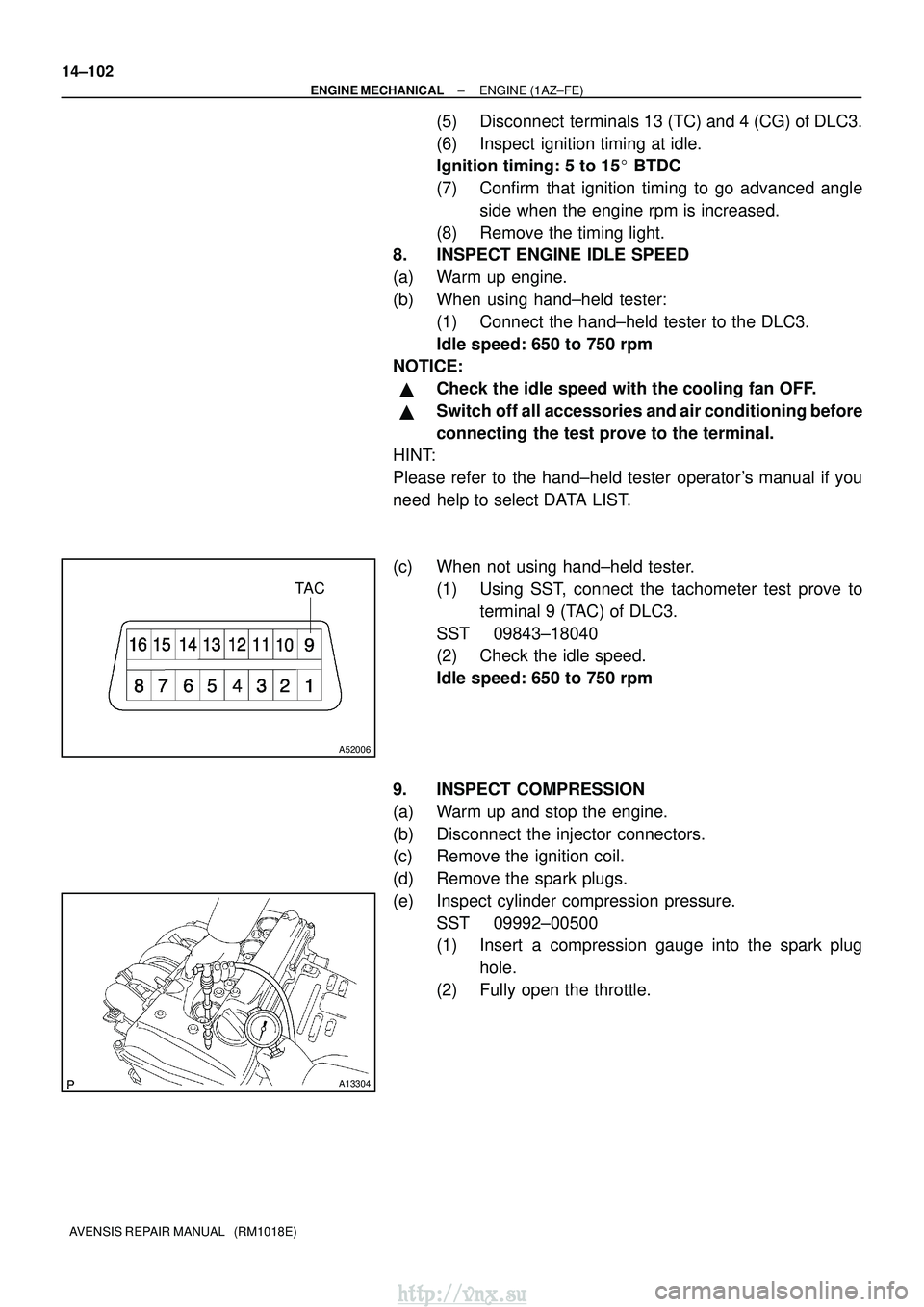
(c) When not using hand±held tester.
(1) Using SST, connect the tachometer test prove toterminal 9 (TAC) of DLC3.
SST 09843±18040
(2) Check the idle speed.
Idle speed: 650 to 750 rpm
9. INSPECT COMPRESSION
(a) Warm up and stop the engine.
(b) Disconnect the injector connectors.
(c) Remove the ignition coil.
(d) Remove the spark plugs.
(e) Inspect cylinder compression pressure. SST 09992±00500
(1) Insert a compression gauge into the spark plughole.
(2) Fully open the throttle.
http://vnx.su
Page 600 of 2234
±
ENGINE MECHANICALENGINE(1AZ±FE)
14±103
AVENSIS REPAIR MANUAL (RM1018E)
(3)While cranking the engine, measure the compres-
sion pressure.
Compression pressure:
1,300 kPa (13.3 kgf/cm
2, 189 psi)
Minimum pressure:
1000 kPa (10.2 kgf/cm
2, 145 psi)
Difference between each cylinder:
100 kPa (1.0 kgf/cm
2, 14 psi)
NOTICE:
�Always use a fully charged battery to obtain engine
speed of 250 rpm or more.
�Check other cylinder's compression pressure in the
same way.
�This measurement must be done in as short a time as
possible.
(4)If the cylinder compression is low, pour a small amount of engine oil into the cylinder through the
spark plug hole and inspect again.
HINT:
�If adding oil increases the compression, the piston rings
and/or cylinder bore may be worn or damaged.
�If pressure stays low, a valve may be sticking or seating
improperly, or there may be leakage past the gasket.
10.INSPECT CO/HC
(a)Start the engine.
(b)Run the engine at 2,500 rpm for approximately 180 seconds.
(c)Insert CO/HC meter testing probe at least 40 cm (1.3 ft) into the tail\
pipe during idling.
(d)Check CO/HC concentration at idle. Idle CO concentration: 0 to 0.5 %
Idle HC concentration: Applicable local regulation
(e)If the CO/HC concentration does not conform to specifications, perform troubleshooting in the order given below.
(1)Check heated oxygen sensor operation. (See page 12±6)
(2) See the table below for possible causes, and then inspect and repair the applicable causes ifnecessary.
http://vnx.su
Page 604 of 2234
A79033
±
ENGINE MECHANICALENGINE(1AZ±FSE)
14±183
AVENSIS REPAIR MANUAL (RM1018E)
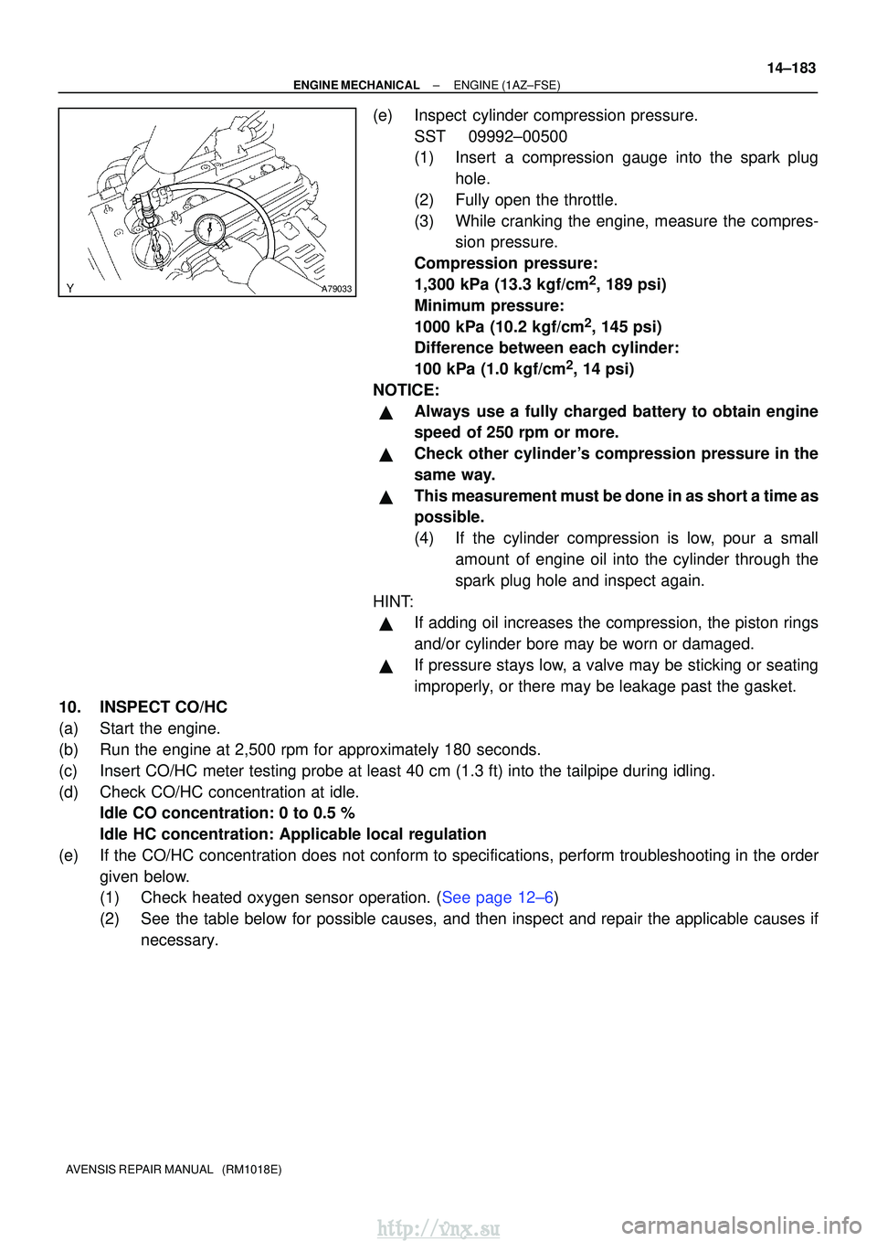
(e)Inspect cylinder compression pressure.
SST09992±00500
(1)Insert a compression gauge into the spark plughole.
(2)Fully open the throttle.
(3)While cranking the engine, measure the compres- sion pressure.
Compression pressure:
1,300 kPa (13.3 kgf/cm
2, 189 psi)
Minimum pressure:
1000 kPa (10.2 kgf/cm
2, 145 psi)
Difference between each cylinder:
100 kPa (1.0 kgf/cm
2, 14 psi)
NOTICE:
�Always use a fully charged battery to obtain engine
speed of 250 rpm or more.
�Check other cylinder's compression pressure in the
same way.
�This measurement must be done in as short a time as
possible.
(4)If the cylinder compression is low, pour a small amount of engine oil into the cylinder through the
spark plug hole and inspect again.
HINT:
�If adding oil increases the compression, the piston rings
and/or cylinder bore may be worn or damaged.
�If pressure stays low, a valve may be sticking or seating
improperly, or there may be leakage past the gasket.
10.INSPECT CO/HC
(a)Start the engine.
(b)Run the engine at 2,500 rpm for approximately 180 seconds.
(c)Insert CO/HC meter testing probe at least 40 cm (1.3 ft) into the tail\
pipe during idling.
(d)Check CO/HC concentration at idle. Idle CO concentration: 0 to 0.5 %
Idle HC concentration: Applicable local regulation
(e)If the CO/HC concentration does not conform to specifications, perform troubleshooting in the order given below.
(1)Check heated oxygen sensor operation. (See page 12±6)
(2) See the table below for possible causes, and then inspect and repair the applicable causes ifnecessary.
http://vnx.su
Page 608 of 2234
A61174
SST
Compression Gauge
14±268
±
ENGINE MECHANICAL ENGINE (1CD±FTV)
AVENSIS REPAIR MANUAL (RM1018E)
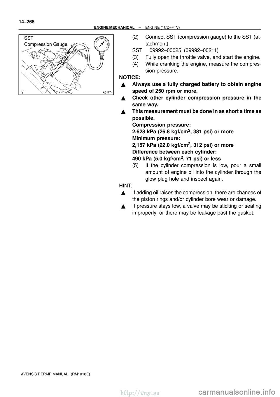
(2) Connect SST (compression gauge) to the SST (at- tachment).
SST 09992±00025 (09992±00211)
(3) Fully open the throttle valve, and start the engine.
(4) While cranking the engine, measure the compres-
sion pressure.
NOTICE:
�Always use a fully charged battery to obtain engine
speed of 250 rpm or more.
�Check other cylinder compression pressure in the
same way.
�This measurement must be done in as short a time as
possible.
Compression pressure:
2,628 kPa (26.8 kgf/cm
2, 381 psi) or more
Minimum pressure:
2,157 kPa (22.0 kgf/cm
2, 312 psi) or more
Difference between each cylinder:
490 kPa (5.0 kgf/cm
2, 71 psi) or less
(5) If the cylinder compression is low, pour a small
amount of engine oil into the cylinder through the
glow plug hole and inspect again.
HINT:
�If adding oil raises the compression, there are chances of
the piston rings and/or cylinder bore wear or damage.
�If pressure stays low, a valve may be sticking or seating
improperly, or there may be leakage past the gasket.
http://vnx.su
Page 610 of 2234
TA C
A52006
A01037
14±2
±
ENGINE MECHANICAL ENGINE (1ZZ±FE/3ZZ±FE)
AVENSIS REPAIR MANUAL (RM1018E)
(5) Inspect ignition timing at idle.
Ignition timing: 8 to 12 �BTDC
NOTICE:
When checking the ignition timing, shift the transmission
to the neutral position.
HINT:
Run the engine at 1,000 to 1,300 rpm for 5 seconds, check that
the engine rpm returns to the idle speed.
(6) Disconnect the terminal 13 (TC) and 4 (CG) of theDLC3.
(7) Inspect ignition timing at idle.
Ignition timing:
10 to 18 �BTDC (1ZZ±FE)
3.5 to 11.5 �BTDC (3ZZ±FE)
(8) Confirm that ignition timing to go advanced angle side when the engine rpm is increased.
(9) Remove the timing light.
(10) Install the cylinder head cover with the 2 nuts and 2 clips.
Torque: 7.0 N �m (71 kgf �cm, 62 in. �lbf)
8. INSPECT ENGINE IDLE SPEED
(a) Warm up engine.
(b) When using hand±held tester: (1) Connect the hand±held tester to the DLC3.
HINT:
Please refer to the hand±held tester operator's manual if you
need help to select DATA LIST.
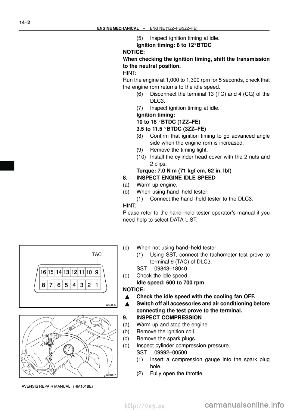
(c) When not using hand±held tester:
(1) Using SST, connect the tachometer test prove toterminal 9 (TAC) of DLC3.
SST 09843±18040
(d) Check the idle speed. Idle speed: 600 to 700 rpm
NOTICE:
�Check the idle speed with the cooling fan OFF.
�Switch off all accessories and air conditioning before
connecting the test prove to the terminal.
9. INSPECT COMPRESSION
(a) Warm up and stop the engine.
(b) Remove the ignition coil.
(c) Remove the spark plugs.
(d) Inspect cylinder compression pressure. SST 09992±00500
(1) Insert a compression gauge into the spark plughole.
(2) Fully open the throttle.
http://vnx.su