Page 329 of 2234
110U2±01
A77915
±
FUELFUEL PRESSURE PULSATION DAMPER
ASSY(1AZ±FE)11±29
AVENSIS REPAIR MANUAL (RM1018E)
FUEL PRESSURE PULSATION DAMPER ASSY(1AZ±FE)
REPLACEMENT
1.DISCHARGE FUEL SYSTEM PRESSURE (See page 11±15)
2.REMOVE ENGINE COVER SUB±ASSY NO.1 (See page 10±26)
3.REMOVE AIR CLEANER CAP SUB±ASSY (See page 10±26)
4.DISCONNECT FUEL TUBE SUB±ASSY (See page 11±26)
SST09268±21010
5.REMOVE FUEL PRESSURE PULSATION DAMPERASSY
(a)Remove the 2 bolts, and then remove the fuel pressure pulsation damper.
6.INSTALL FUEL PRESSURE PULSATION DAMPER ASSY
(a)Apply a light coat of spindle oil or gasoline to a new O±ring, and instal\
l it to the fuel pressure pulsation damper.
(b)Install the fuel pressure pulsation damper with the 2 bolts. Torque: 9.0 N �m (92 kgf�cm, 80 in. �lbf)
7.CONNECT FUEL TUBE SUB±ASSY (See page 11±26)
8. INSTALL AIR CLEANER CAP SUB±ASSY
9.CHECK FOR FUEL LEAKS (See page 11±19)
10.INSTALL ENGINE COVER SUB±ASSY NO.1 (See page 10±26)
http://vnx.su
Page 453 of 2234
A31032
A32639
A77414
Straight
Pin
Key
Groove
14±174
±
ENGINE MECHANICAL CAMSHAFT (1AZ±FE)
AVENSIS REPAIR MANUAL (RM1018E)
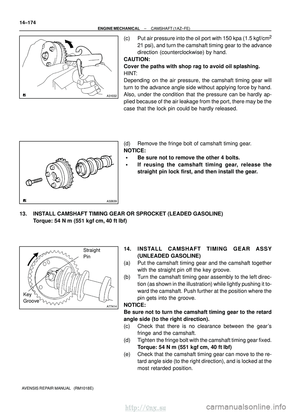
(c) Put air pressure into the oil port with 150 kpa (1.5 kgf/cm2
21 psi), and turn the camshaft timing gear to the advance
direction (counterclockwise) by hand.
CAUTION:
Cover the paths with shop rag to avoid oil splashing.
HINT:
Depending on the air pressure, the camshaft timing gear will
turn to the advance angle side without applying force by hand.
Also, under the condition that the pressure can be hardly ap-
plied because of the air leakage from the port, there may be the
case that the lock pin could be hardly released.
(d) Remove the fringe bolt of camshaft timing gear.
NOTICE:
�Be sure not to remove the other 4 bolts.
�If reusing the camshaft timing gear, release the
straight pin lock first, and then install the gear.
13. INSTALL CAMSHAFT TIMING GEAR OR SPROCKET (LEADED GASOLINE) Torque: 54 N �m (551 kgf� cm, 40 ft�lbf)
14. INSTALL CAMSHAFT TIMING GEAR ASSY (UNLEADED GASOLINE)
(a) Put the camshaft timing gear and the camshaft together with the straight pin off the key groove.
(b) Turn the camshaft timing gear assembly to the left direc- tion (as shown in the illustration) while lightly pushing it to-
ward the camshaft. Push further at the position where the
pin gets into the groove.
NOTICE:
Be sure not to turn the camshaft timing gear to the retard
angle side (to the right direction).
(c) Check that there is no clearance between the gear's fringe and the camshaft.
(d) Tighten the fringe bolt with the camshaft timing gear fixed. Torque: 54 N� m (551 kgf�cm, 40 ft�lbf)
(e) Check that the camshaft timing gear can move to the re- tard angle side (to the right direction), and is locked at the
most retarded position.
http://vnx.su
Page 460 of 2234
141BQ±01
A77339
A77284
14±240
±
ENGINE MECHANICALCAMSHAFT(1AZ±FSE)
AVENSIS REPAIR MANUAL (RM1018E)
REPLACEMENT
1.DISCHARGE FUEL SYSTEM PRESSURE (See page 11±30)
2.REMOVE RADIATOR SUPPORT OPENING COVER
3.REMOVE ENGINE ROOM COVER SIDE
4.REMOVE ENGINE UNDER COVER RH 5.REMOVE ENGINE COVER SUB±ASSY NO.1
(a)Remove the 2 nuts and the engine cover No. 1.
6.REMOVE IGNITION COIL ASSY
(a)Remove the 4 bolts and the ignition coils.
7.REMOVE FUEL PRESSURE PULSATION DAMPER ASSY
8.REMOVE FUEL TUBE SUB±ASSY (See page 11±33)
9.REMOVE FUEL PIPE SUB±ASSY NO.1 (See page 11±52) SST 09023±12900
10.REMOVE FUEL PUMP ASSY (See page 11±52)
11.REMOVE CYLINDER HEAD COVER SUB±ASSY (See page 14±222)
12. SET NO. 1 CYLINDER TO TDC/COMPRESSION
(a) Turn the crankshaft pulley, and align its groove with timingmark 0 of the timing chain cover.
http://vnx.su
Page 462 of 2234
A77309
15973
481062
A56228
A77413
Advance
Side Port
A31032
14±242
±
ENGINE MECHANICAL CAMSHAFT (1AZ±FSE)
AVENSIS REPAIR MANUAL (RM1018E)
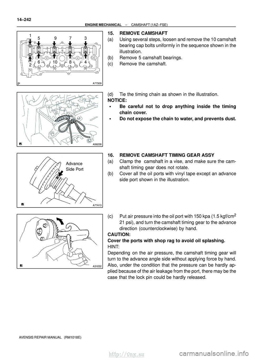
15. REMOVE CAMSHAFT
(a) Using several steps, loosen and remove the 10 camshaft bearing cap bolts uniformly in the sequence shown in the
illustration.
(b) Remove 5 camshaft bearings.
(c) Remove the camshaft.
(d) Tie the timing chain as shown in the illustration.
NOTICE:
�Be careful not to drop anything inside the timing
chain cover.
�Do not expose the chain to water, and prevents dust.
16. REMOVE CAMSHAFT TIMING GEAR ASSY
(a) Clamp the camshaft in a vise, and make sure the cam- shaft timing gear does not rotate.
(b) Cover all the oil ports with vinyl tape except an advance side port shown in the illustration.
(c) Put air pressure into the oil port with 150 kpa (1.5 kgf/cm
2
21 psi), and turn the camshaft timing gear to the advance
direction (counterclockwise) by hand.
CAUTION:
Cover the ports with shop rag to avoid oil splashing.
HINT:
Depending on the air pressure, the camshaft timing gear will
turn to the advance angle side without applying force by hand.
Also, under the condition that the pressure can be hardly ap-
plied because of the air leakage from the port, there may be the
case that the lock pin could be hardly released.
http://vnx.su
Page 465 of 2234
A77395
Engine
Front
A77396
HookPinTurn
Disconnect
A77397
Push Turn
Plunger
±
ENGINE MECHANICALCAMSHAFT(1AZ±FSE)
14±245
AVENSIS REPAIR MANUAL (RM1018E)
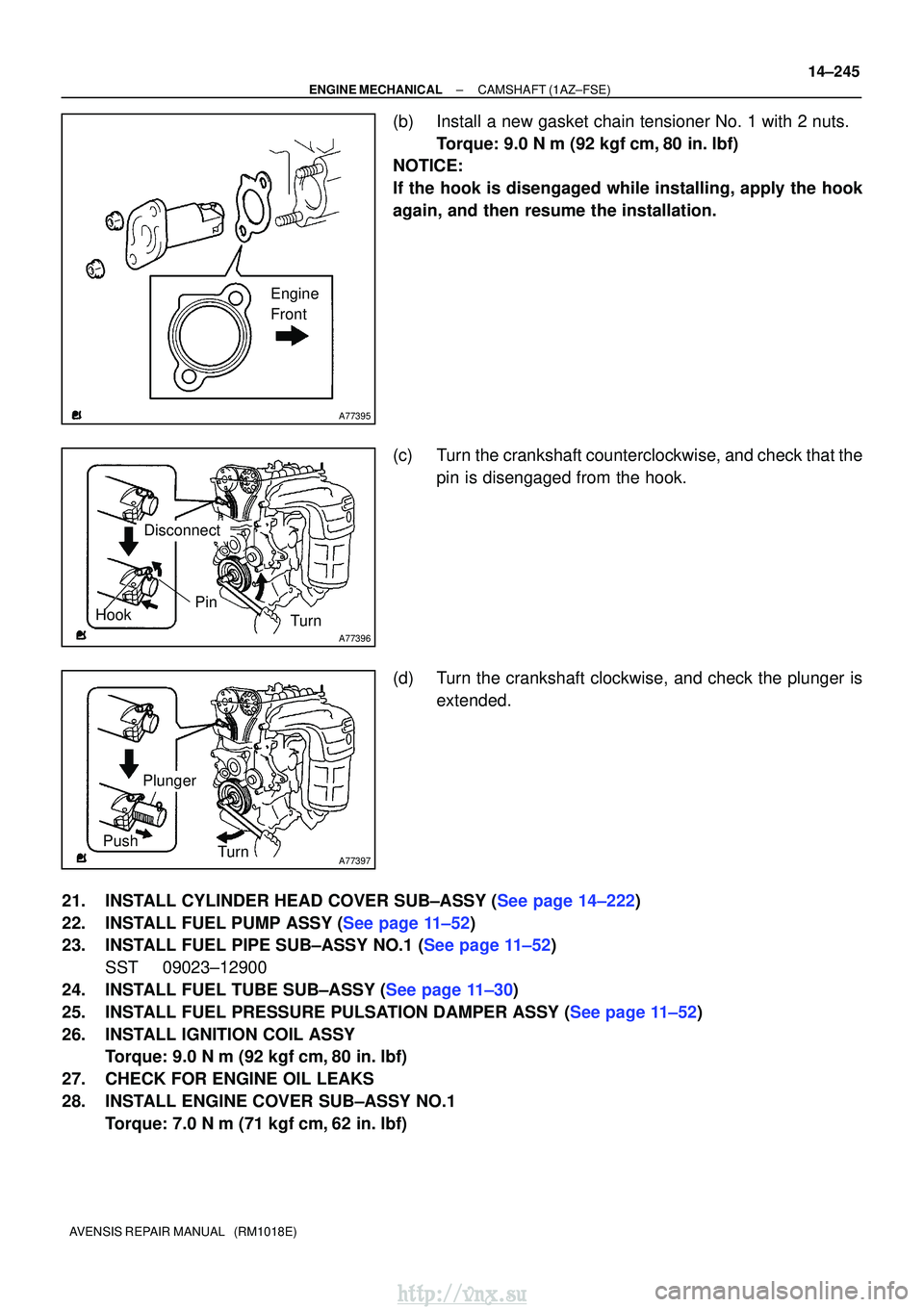
(b)Install a new gasket chain tensioner No. 1 with 2 nuts.
Torque: 9.0 N �m (92 kgf�cm,80 in. �lbf)
NOTICE:
If the hook is disengaged while installing, apply the hook
again, and then resume the installation.
(c)Turn the crankshaft counterclockwise, and check that the
pin is disengaged from the hook.
(d)Turn the crankshaft clockwise, and check the plunger is extended.
21.INSTALL CYLINDER HEAD COVER SUB±ASSY (See page 14±222)
22.INSTALL FUEL PUMP ASSY (See page 11±52)
23.INSTALL FUEL PIPE SUB±ASSY NO.1 (See page 11±52) SST 09023±12900
24.INSTALL FUEL TUBE SUB±ASSY (See page 11±30)
25.INSTALL FUEL PRESSURE PULSATION DAMPER ASSY (See page 11±52)
26. INSTALL IGNITION COIL ASSY Torque: 9.0 N �m (92 kgf �cm, 80 in. �lbf)
27. CHECK FOR ENGINE OIL LEAKS
28. INSTALL ENGINE COVER SUB±ASSY NO.1 Torque: 7.0 N �m (71 kgf �cm, 62 in. �lbf)
http://vnx.su
Page 486 of 2234
A32556
A62190
Advance
Side Path
Retard Side
Path
Open
Close
Rubber
Vinyl Tape
Open Close
A62191
Advanced
Side Path
Retard
Side Path
14±68
±
ENGINE MECHANICAL CAMSHAFT (1ZZ±FE/3ZZ±FE)
AVENSIS REPAIR MANUAL (RM1018E)
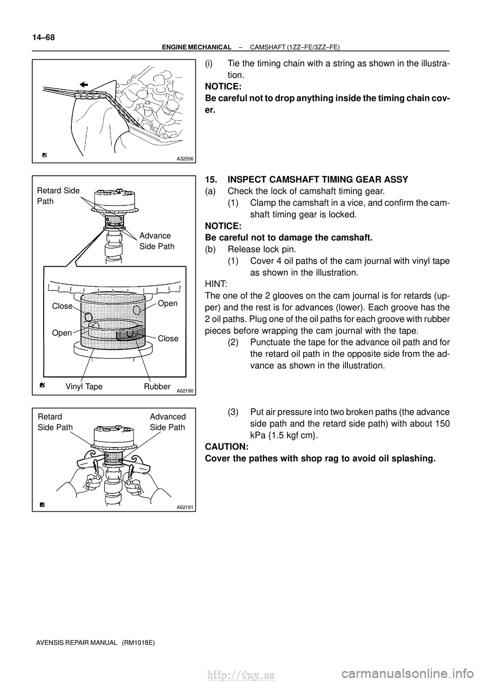
(i) Tie the timing chain with a string as shown in the illustra- tion.
NOTICE:
Be careful not to drop anything inside the timing chain cov-
er.
15. INSPECT CAMSHAFT TIMING GEAR ASSY
(a) Check the lock of camshaft timing gear.
(1) Clamp the camshaft in a vice, and confirm the cam-shaft timing gear is locked.
NOTICE:
Be careful not to damage the camshaft.
(b) Release lock pin. (1) Cover 4 oil paths of the cam journal with vinyl tapeas shown in the illustration.
HINT:
The one of the 2 glooves on the cam journal is for retards (up-
per) and the rest is for advances (lower). Each groove has the
2 oil paths. Plug one of the oil paths for each groove with rubber
pieces before wrapping the cam journal with the tape. (2) Punctuate the tape for the advance oil path and for
the retard oil path in the opposite side from the ad-
vance as shown in the illustration.
(3) Put air pressure into two broken paths (the advance side path and the retard side path) with about 150
kPa {1.5 kgf� cm}.
CAUTION:
Cover the pathes with shop rag to avoid oil splashing.
http://vnx.su
Page 487 of 2234
A62192
Hold Pressure
DecompressAdvanced
Side Path
Retard
Side Path
A62190
Advance
Side Path
Retard Side
Path
Open
Close
Rubber
Vinyl Tape
Open Close
±
ENGINE MECHANICAL CAMSHAFT (1ZZ±FE/3ZZ±FE)
14±69
AVENSIS REPAIR MANUAL (RM1018E)
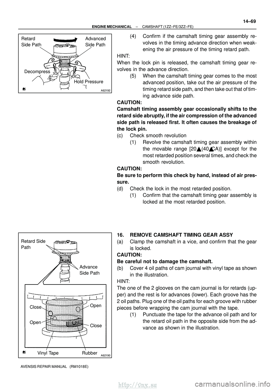
(4) Confirm if the camshaft timing gear assembly re-
volves in the timing advance direction when weak-
ening the air pressure of the timing retard path.
HINT:
When the lock pin is released, the camshaft timing gear re-
volves in the advance direction. (5) When the camshaft timing gear comes to the most
advanced position, take out the air pressure of the
timing retard side path, and then take out that of tim-
ing advance side path.
CAUTION:
Camshaft timing assembly gear occasionally shifts to the
retard side abruptly, if the air compression of the advanced
side path is released first. It often causes the breakage of
the lock pin.
(c) Check smooth revolution (1) Revolve the camshaft timing gear assembly withinthe movable range [20� (40�CA)] except for the
most retarded position several times, and check the
smooth revolution.
CAUTION:
Be sure to perform this check by hand, instead of air pres-
sure.
(d) Check the lock in the most retarded position. (1) Confirm that the camshaft timing gear assembly is
locked at the most retarded position.
16. REMOVE CAMSHAFT TIMING GEAR ASSY
(a) Clamp the camshaft in a vice, and confirm that the gear is locked.
CAUTION:
Be careful not to damage the camshaft.
(b) Cover 4 oil paths of cam journal with vinyl tape as shown
in the illustration.
HINT:
The one of the 2 glooves on the cam journal is for retards (up-
per) and the rest is for advances (lower). Each groove has the
2 oil paths. Plug one of the oil paths for each groove with rubber
pieces before wrapping the cam journal with the tape. (1) Punctuate the tape for the advance oil path and for
the retard oil path in the opposite side from the ad-
vance as shown in the illustration.
http://vnx.su
Page 488 of 2234
A62191
Advanced
Side Path
Retard
Side Path
A62192
Hold Pressure
Decompress Advanced
Side Path
Retard
Side Path
A62193
Straight Pin
Fringe Bolt
A62194
Straight Pin
Key Groove
14±70
±
ENGINE MECHANICAL CAMSHAFT (1ZZ±FE/3ZZ±FE)
AVENSIS REPAIR MANUAL (RM1018E)
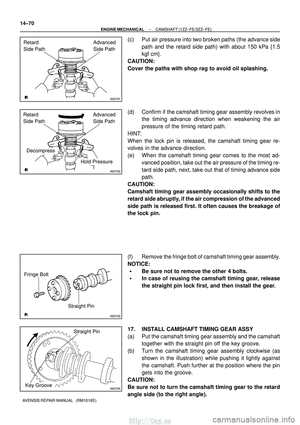
(c) Put air pressure into two broken paths (the advance side path and the retard side path) with about 150 kPa {1.5
kgf�cm}.
CAUTION:
Cover the paths with shop rag to avoid oil splashing.
(d) Confirm if the camshaft timing gear assembly revolves in the timing advance direction when weakening the air
pressure of the timing retard path.
HINT:
When the lock pin is released, the camshaft timing gear re-
volves in the advance direction.
(e) When the camshaft timing gear comes to the most ad- vanced position, take out the air pressure of the timing re-
tard side path, next, take out that of timing advance side
path.
CAUTION:
Camshaft timing gear assembly occasionally shifts to the
retard side abruptly, if the air compression of the advanced
side path is released first. It often causes the breakage of
the lock pin.
(f) Remove the fringe bolt of camshaft timing gear assembly.
NOTICE:
�Be sure not to remove the other 4 bolts.
�In case of reusing the camshaft timing gear, release
the straight pin lock first, and then install the gear.
17. INSTALL CAMSHAFT TIMING GEAR ASSY
(a) Put the camshaft timing gear assembly and the camshaft together with the straight pin off the key groove.
(b) Turn the camshaft timing gear assembly clockwise (as shown in the illustration) while pushing it lightly against
the camshaft. Push further at the position where the pin
gets into the groove.
CAUTION:
Be sure not to turn the camshaft timing gear to the retard
angle side (to the right angle).
http://vnx.su