Page 1349 of 1574

1-2 HOW TO USE ELECTRICAL WIRING DIAGRAM
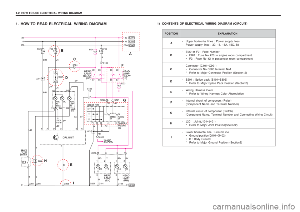
1. HOW TO READ ELECTRICAL WIRING DIAGRAM1) CONTENTS OF ELECTRICAL WIRING DIAGRAM (CIRCUIT)
POSITION EXPLANATION
- Upper horizontal lines : Power supply lines
- Power supply lines : 30, 15, 15A, 15C, 58
- Ef20 or F2 : Fuse Number
• Ef20 : Fuse No #20 in engine room compartment
F2 : Fuse No #2 in passenger room compartment
- Connector (C101~C901) Connector No C203 terminal No1
* Refer to Major Connector Position (Section 2)
- S201 : Splice pack (S101~S306) * Refer to Major Splice Pack Position (Section2)
- Wiring Harness Color * Refer to Wiring Harness Color Abbreviation
- Internal circuit of component (Relay) (Component Name and Terminal Number)
- Internal circuit of component (Switch) (Component Name, Terminal Number and Connecting Wiring Circuit)
- J201 : Joint(J101~J401) * Refer to Major Joint Position(Section2)
- Lower horizontal line : Ground line Ground position(G101~G402)
B : Body Ground
* Refer to Major Ground Position (Section2)
A
B C D E
F
G
H
I
A
B
C
D F
G
E I
H
Page 1350 of 1574

HOW TO USE ELECTRICAL WIRING DIAGRAM 1-3
Connector DiodeFuse in engine room fuse & relay box Fuse in passenger room fuse box Ground Joint - Inline wire connected point Splice pack(Junction connector)
C D
Ef F
G J
S
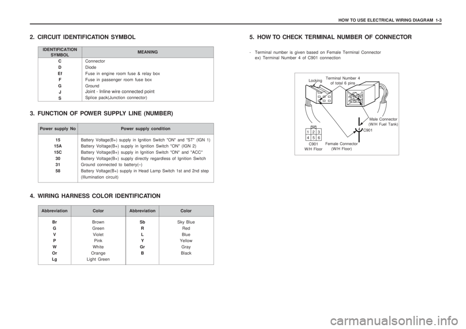
2. CIRCUIT IDENTIFICATION SYMBOL
3. FUNCTION OF POWER SUPPLY LINE (NUMBER)
IDENTIFICATION SYMBOL MEANING
Power supply No Power supply condition
Battery Voltage(B+) supply in Ignition Switch "ON" and "ST" (IGN 1)
Battery Voltage(B+) supply in Ignition Switch "ON" (IGN 2) Battery Voltage(B+) supply in Ignition Switch "ON" and "ACC"Battery Voltage(B+) supply directly regardless of Ignition Switch Ground connected to battery(
–)
Battery Voltage(B+) supply in Head Lamp Switch 1st and 2nd step
(Illumination circuit)
15
15A 15C
30 31 58
Abbreviation Color
BrownGreen Violet Pink
White
Orange
Light Green
Br
GV P
W
Or
LgAbbreviation Color
Sky BlueRed
Blue
Yellow
Gray
Black
Sb
RL Y
Gr B
4. WIRING HARNESS COLOR IDENTIFICATION 5. HOW TO CHECK
TERMINAL NUMBER OF CONNECTOR
- Terminal number is given based on Female Terminal Connector ex) Terminal Number 4 of C901 connection
Locking Terminal Number 4
of total 6 pins
Male Connector
(W/H Fuel Tank)
4 C901
Female Connector (W/H Floor)
C901
W/H Floor 13
2
46 5
Page 1352 of 1574
2-2 POSITION OF CONNECTORS AND GROUNDS
1. POSITION OF CONNECTOR, GROUND & SPLICE PACK
W/H - ENG. MAIN W/H - ENGINEW/H - MAIN W/H - FLOORW/H - T/M
Page 1353 of 1574

POSITION OF CONNECTORS AND GROUNDS 2-3
C361 C371C381C401C402C403 22
88626 White
ColorlessColorlessColorlessColorlessColorless Main - Co-Driver DoorFloor - Rear Left DoorFloor - Rear Right DoorFloor - Tail GateFloor - Tail GateFloor - Tail Gate
Inside Co-Driver Side Cowl PanelCenter 'B' PillarCenter Left 'B' PillarBehind The Left LampBehind The Left LampBehind The Left Lamp
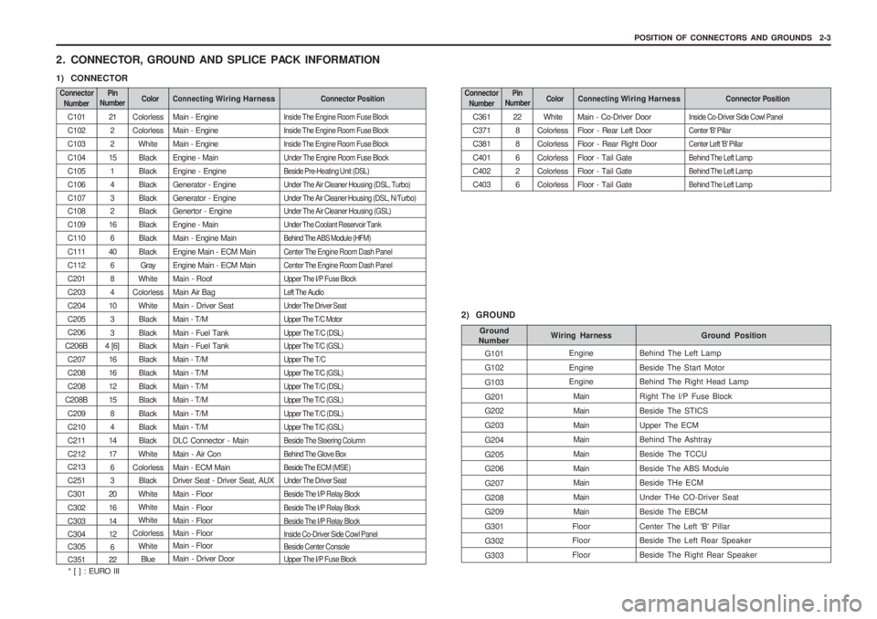
2. CONNECTOR, GROUND AND SPLICE PACK INFORMATION
1) CONNECTOR
Connector
Number Connecting Wiring HarnessConnector PositionColorPin
Number
C101 C102C103C104C105C106C107 C108 C109C110C111C112C201C203C204C205 C206
C206B C207 C208C208
C208B C209C210C211C212 C213 C251C301C302C303 C304 C305 C351212 2
15 143 2
16 6
40 6 84
10 33
4 [6]
1616121584
1417 6 3
20 1614 12 6
22 Colorless Colorless
WhiteBlackBlackBlackBlack Black BlackBlackBlack Gray
White
Colorless WhiteBlackBlack Black BlackBlackBlackBlackBlackBlackBlack
White
Colorless Black
White WhiteWhite
Colorless White
Blue Main - Engine Main - EngineMain - EngineEngine - MainEngine - EngineGenerator - EngineGenerator - Engine Genertor - Engine Engine - MainMain - Engine MainEngine Main - ECM MainEngine Main - ECM MainMain - RoofMain Air BagMain - Driver SeatMain - T/MMain - Fuel Tank Main - Fuel Tank Main - T/MMain - T/MMain - T/MMain - T/MMain - T/MMain - T/MDLC Connector - MainMain - Air ConMain - ECM Main Driver Seat - Driver Seat, AUX Main - FloorMain - Floor Main - Floor Main - FloorMain - Floor Main - Driver DoorInside The Engine Room Fuse Block Inside The Engine Room Fuse BlockInside The Engine Room Fuse BlockUnder The Engine Room Fuse BlockBeside Pre-Heating Unit (DSL)Under The Air Cleaner Housing (DSL, Turbo)Under The Air Cleaner Housing (DSL, N/Turbo) Under The Air Cleaner Housing (GSL) Under The Coolant Reservoir TankBehind The ABS Module (HFM)Center The Engine Room Dash PanelCenter The Engine Room Dash PanelUpper The I/P Fuse BlockLeft The AudioUnder The Driver SeatUpper The T/C MotorUpper The T/C (DSL) Upper The T/C (GSL) Upper The T/CUpper The T/C (GSL)Upper The T/C (DSL)Upper The T/C (GSL)Upper The T/C (DSL)Upper The T/C (GSL)Beside The Steering ColumnBehind The Glove BoxBeside The ECM (MSE) Under The Driver Seat Beside The I/P Relay BlockBeside The I/P Relay BlockBeside The I/P Relay Block Inside Co-Driver Side Cowl Panel Beside Center ConsoleUpper The I/P Fuse Block
Connector
Number Connecting Wiring HarnessConnector PositionColorPin
Number
2) GROUND
G101 G102 G103G201 G202 G203G204G205 G206 G207G208 G209 G301G302G303 Ground Position
Wiring Harness
Ground
Number
Behind The Left LampBeside The Start Motor Behind The Right Head Lamp Right The I/P Fuse BlockBeside The STICSUpper The ECM Behind The Ashtray Beside The TCCUBeside The ABS Module Beside THe ECM Under THe CO-Driver SeatBeside The EBCMCenter The Left 'B' Pillar Beside The Left Rear Speaker Beside The Right Rear Speaker
Engine Engine Engine
Main MainMain Main MainMain Main MainMain
Floor Floor Floor
* [ ] : EURO III
Page 1354 of 1574
POSITION OF CONNECTORS AND GROUNDS 2-5
3. WIRING HARNESS, CONNECTOR & GROUND LOCATION
1) W/H ENGINE ROOM • GSL DSL
C109
C111 C112
C101, C102 S101, C104C103
C109 C101,
C102
S101,
C104 C103
Page 1359 of 1574
CONTENTS
1. FUSIBLE LINK FUSE BLOCK & ENGINE ROOM FUSE BLOCK POWER DISTRIBUTION .................................................... 3-2
2. I/P FUSE BLOCK POWER DISTRIBUTION ..................................... 3-3
SECTION 3
WIRING DIAGRAM FOR POWER SUPPLIES
Page 1360 of 1574
3-2 WIRING DIAGRAM FOR POWER SUPPLIES
1. FUSIBLE LINK FUSE BLOCK & ENGINE ROOM FUSE BLOCK POWER DISTRIBUTION
Page 1365 of 1574
SECTION 4
USAGE AND CAPACITY OF FUSES IN FUSE BLOCK
1. ENGINE ROOM FUSE & RELAY BLOCK ....................................... 4-2
2. I/P FUSE BLOCK ............................................................................... 4-3
3. POSITION OF RELAY, CONTROL UNIT AND PARTS NUMBER .. 4-4 CONTENTS