Page 1222 of 1574
9A-20 BODY WIRING SYSTEM
GASOLINE ENGINE (MSE)1 ECU Main Wiring Connector
2 ECU Main Wiring Connector
3 Crankshaft Position Sensor
4 Oil Pressure Switch
5 Knock Sensor 2
6 Hot-Film Air Mass Sensor
7 Injector 6
8 Injector 5
9 Injector 4
10 Injector 3
11 Injector 2
12 Injector 1
13 Camshaft Adjustment Magnet 14 Ignition Coil 3
15 Ignition Coil 2
16 Ignition Coil 1
17 Temperature Sensor (Gauge)
18 Double Sensor
19 Camshaft Position Sensor
20 Knock Sensor 1
21 Throttle Regulating Unit
22 Resonance Flap
23 Main Wiring Connector
2 4 ECU
25 ECU Engine Wiring Connector
26 ECU Engine Wiring Connector
Page 1223 of 1574
BODY WIRING SYSTEM 9A-21
GASOLINE ENGINE (HFM)1 ECU
2 Main Wiring Connector
3 Crankshaft Position Sensor
4 Knock Sensor
5 Hot-Film Air Mass Sensor
6 Aspiration Sensor
7 Throttle Regulating Unit
8 Knock Sensor
9 Camshaft Position Sensor
10 Ignition Coil 3
11 Ignition Coil 2
12 Ignition Coil 1 13 Injector 6
14 Injector 5
15 Injector 4
16 Injector 3
17 Injector 2
18 Injector 1
19 Camshaft Adjustment Magnet
20 Resonance Flap
21 Temperature Sensor (Gauge)
22 Double Sensor
23 Ground
Page 1224 of 1574
9A-22 BODY WIRING SYSTEM
DIESEL ENGINE1 Preheating Unit
2 Main Wiring Connector
3 Glow Plug 1
4 Glow Plug 2 5 Glow Plug 3
6 Glow Plug 4
7 Glow Plug 5
8 Water Temperature Sensor (Gauge)
Page 1225 of 1574
BODY WIRING SYSTEM 9A-23
MANUAL TRANSMISSION1 Main Wiring Connector ......................Diesel E/G
2 Main Wiring Connector ..................Gasoline E/G
3 Main Wiring Connector .........................Gasoline
(E32, E23) E/G
4 Back Up Switch 5 Oil Pressure Switch
6 Start Motor Solenoid
7 Micro Switch
8 Speed Sensor (Turbo Diesel Engine Only)
Page 1238 of 1574

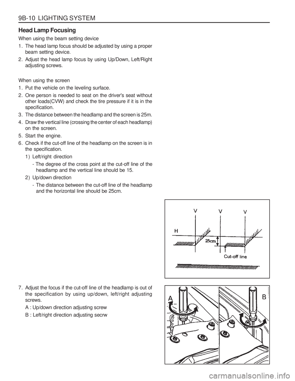
9B-10 LIGHTING SYSTEM Head Lamp Focusing When using the beam setting device
1. The head lamp focus should be adjusted by using a properbeam setting device.
2. Adjust the head lamp focus by using Up/Down, Left/Right adjusting screws.
When using the screen
1. Put the vehicle on the leveling surface.
2. One person is needed to seat on the driver's seat without other loads(CVW) and check the tire pressure if it is in the specification.
3. The distance between the headlamp and the screen is 25m.
4. Draw the vertical line (crossing the center of each headlamp) on the screen.
5. Start the engine.
6. Check if the cut-off line of the headlamp on the screen is in the specification.
1 ) Left/right direction
- The degree of the cross point at the cut-off line of theheadlamp and the vertical line should be 15.
2 ) Up/down direction - The distance between the cut-off line of the headlampand the horizontal line should be 25cm.
7. Adjust the focus if the cut-off line of the headlamp is out of
the specification by using up/down, left/right adjusting screws. A : Up/down direction adjusting screwB : Left/right direction adjusting secrw
Page 1252 of 1574
INSTRUMENTATION/DRIVER INFORMATION 9E-3
COMBINATION METER
COMPONENT LOCATOR
1. Speedometer
2. Odometer
3. Trip odometer
4. Tachometer
5. Coolant temperature gauge
6. Fuel gauge
7. Low fuel level warning light
8. Turn signal indicator (left)
9. Turn signal indicator (right)
10. Outside rearview mirror & tailgate heating switch
11. Reset button
12. Auto shift indicator*
13. Door open warning light
14. TCS indicator (equipped with ABD)*
21. ABS warning light* 22. EBD warning light*
23. ECS / SPORT warning light*
24. 4 - wheel warning light*
25. 4 - wheel high indicator
26. 4 - wheel low indicator
27. WINTER indicator
28. POWER indicator
29. High beam indicator
15. Alternator warning light
16. Engine oil pressure warning light
17. Brake system warning light
18. Glow indicator light (For Diesel engine)
19. Airbag warning light*
20. Seat belt reminder
Page 1308 of 1574

CONTROL UNITS AND SYSTEM 9U-3
FUNCTION DESCRIPTION
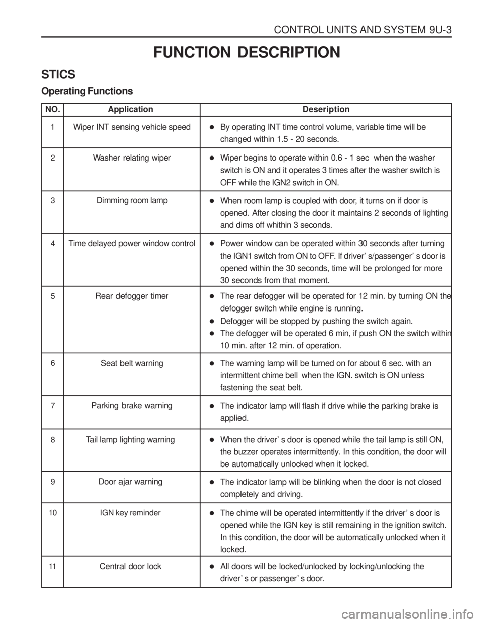
STICS Operating Functions
NO.Application Deseription
1 Wiper INT sensing vehicle speed �By operating INT time control volume, variable time will be changed within 1.5 - 20 seconds.
2 Washer relating wiper �Wiper begins to operate within 0.6 - 1 sec when the washer switch is ON and it operates 3 times after the washer switch is OFF while the IGN2 switch in ON.
3 Dimming room lamp
�When room lamp is coupled with door, it turns on if door is opened. After closing the door it maintains 2 seconds of lightingand dims off whithin 3 seconds.
4 Time delayed power window control �Power window can be operated within 30 seconds after turning
the IGN1 switch from ON to OFF. If driver ’s/passenger ’s door is
opened within the 30 seconds, time will be prolonged for more 30 seconds from that moment.
5 Rear defogger timer �The rear defogger will be operated for 12 min. by turning ON the defogger switch while engine is running.
� Defogger will be stopped by pushing the switch again.
� The defogger will be operated 6 min, if push ON the switch within10 min. after 12 min. of operation.
6
Seat belt warning �The warning lamp will be turned on for about 6 sec. with an intermittent chime bell when the IGN. switch is ON unlessfastening the seat belt.
7 Parking brake warning
�The indicator lamp will flash if drive while the parking brake is applied.
8 Tail lamp lighting warning �When the driver ’s door is opened while the tail lamp is still ON,
the buzzer operates intermittently. In this condition, the door will be automatically unlocked when it locked.
9 Door ajar warning
�The indicator lamp will be blinking when the door is not closed completely and driving.
10 IGN key reminder
�The chime will be operated intermittently if the driver ’s door is
opened while the IGN key is still remaining in the ignition switch. In this condition, the door will be automatically unlocked when itlocked.
11 Central door lock �All doors will be locked/unlocked by locking/unlocking the driver ’s or passenger ’s door.
Page 1315 of 1574

MUSSO-SPORTS 1A-3
SUPPLEMENT
HUBER EGR
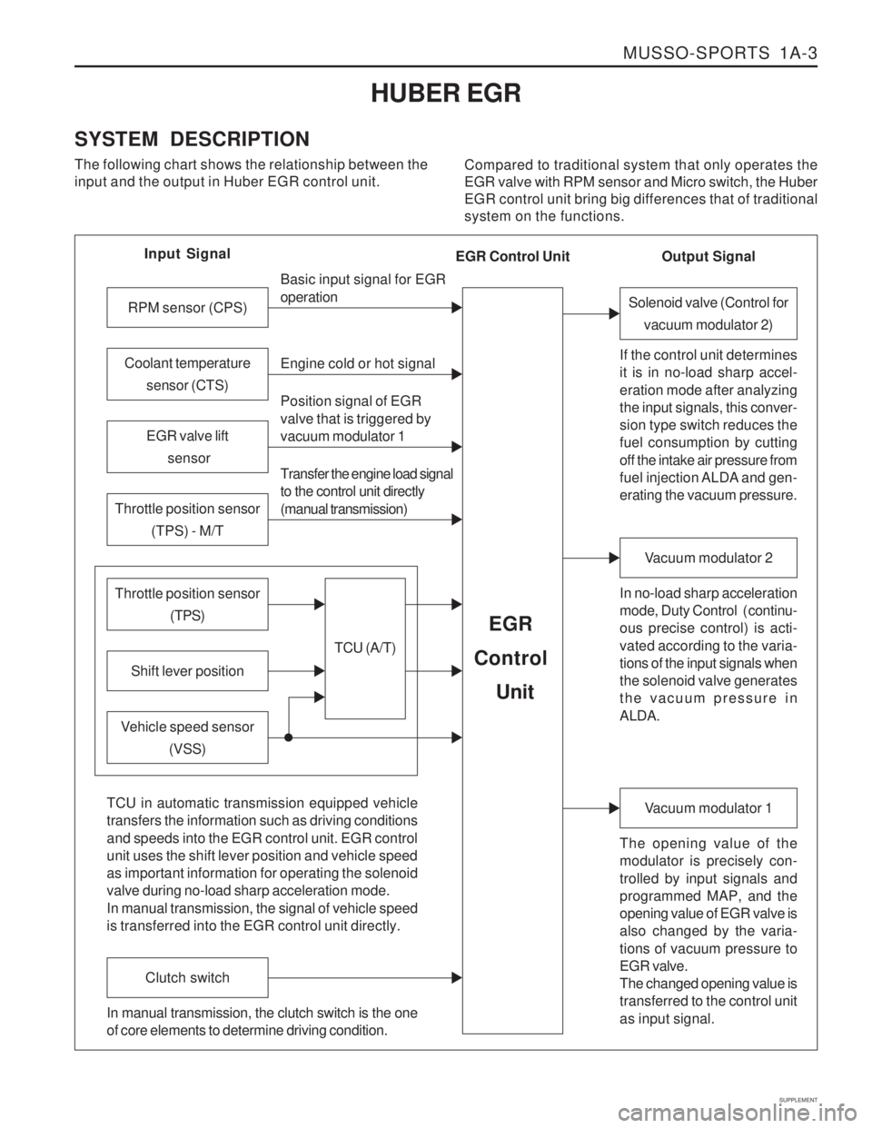
SYSTEM DESCRIPTION The following chart shows the relationship between the input and the output in Huber EGR control unit. Compared to traditional system that only operates theEGR valve with RPM sensor and Micro switch, the HuberEGR control unit bring big differences that of traditionalsystem on the functions.
Input Signal
RPM sensor (CPS)
EGR valve lift sensor
Throttle position sensor (TPS) - M/T
Shift lever position
Throttle position sensor (TPS)
Vehicle speed sensor(VSS) Basic input signal for EGR operation Engine cold or hot signal
Position signal of EGR valve that is triggered by vacuum modulator 1 Transfer the engine load signal to the control unit directly (manual transmission)
TCU (A/T)
EGR
Control
Unit
Coolant temperature sensor (CTS)
Solenoid valve (Control forvacuum modulator 2)
If the control unit determines it is in no-load sharp accel- eration mode after analyzing the input signals, this conver- sion type switch reduces the fuel consumption by cutting off the intake air pressure from
fuel injection ALDA and gen- erating the vacuum pressure. In no-load sharp acceleration
mode, Duty Control ( continu- ous precise control) is acti- vated according to the varia- tions of the input signals when the solenoid valve generates the vacuum pressure in ALDA.
Vacuum modulator 2
The opening value of the modulator is precisely con- trolled by input signals and programmed MAP, and the opening value of EGR valve is also changed by the varia- tions of vacuum pressure to EGR valve. The changed opening value is transferred to the control unit as input signal.
Vacuum modulator 1
TCU in automatic transmission equipped vehicle transfers the information such as driving conditions and speeds into the EGR control unit. EGR control unit uses the shift lever position and vehicle speed as important information for operating the solenoid valve during no-load sharp acceleration mode. In manual transmission, the signal of vehicle speed is transferred into the EGR control unit directly.
Clutch switch
In manual transmission, the clutch switch is the one of core elements to determine driving condition. Output Signal
EGR Control Unit