2003 SSANGYONG MUSSO ABS
[x] Cancel search: ABSPage 1079 of 1574
TRANSFER CASE (PART TIME 4408) 5D1-27
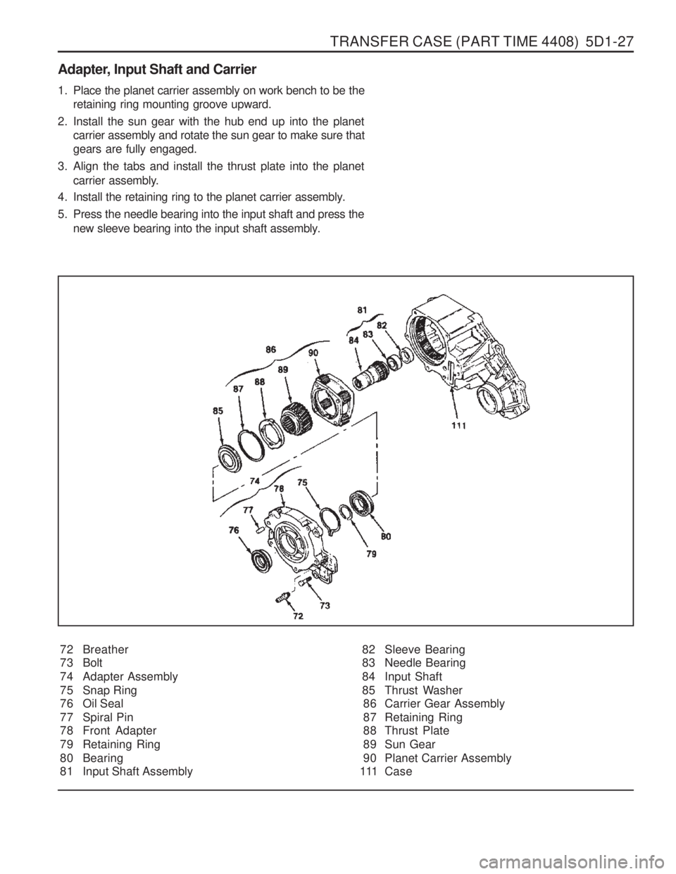
Adapter, Input Shaft and Carrier72 Breather
73 Bolt
74 Adapter Assembly
75 Snap Ring
76 Oil Seal
77 Spiral Pin
78 Front Adapter
79 Retaining Ring
80 Bearing
81 Input Shaft Assembly
1. Place the planet carrier assembly on work bench to be the
retaining ring mounting groove upward.
2. Install the sun gear with the hub end up into the planet carrier assembly and rotate the sun gear to make sure that gears are fully engaged.
3. Align the tabs and install the thrust plate into the planet carrier assembly.
4. Install the retaining ring to the planet carrier assembly.
5. Press the needle bearing into the input shaft and press the new sleeve bearing into the input shaft assembly.
82 Sleeve Bearing
83 Needle Bearing
84 Input Shaft
85 Thrust Washer86 Carrier Gear Assembly
87 Retaining Ring
88 Thrust Plate
89 Sun Gear
90 Planet Carrier Assembly
111 Case
Page 1095 of 1574

5D2-6 TRANSFER CASE (TOD) Input/Output diagram TOD control unit and main wiring harness is linked by 30 pin
connector. Each pin joins with switche and actuator whosedetails refer to the below diagram.
Battery Power
Ignition ON/OFF
Position Encoder 1
Position Encoder 2
Position Encoder 3
Position Encoder 4
4H / 4L Switch Signal
A/T “N” Position Signal
Speed / TPS Supply
Front Speed Sensor Input
Rear Speed Sensor Input
ABS Operation Signal
Brake Switch Signal
4 5271028309241611292526
19 CAN H
CAN L
Shift Motor output port (LO-HI)
Shift Motor output port (HI-LO)
EMC
'4L' Indicator
Position Return
'4WD CHECK' IND
TPS/speed Sensor Ground (Speed / TPS Return)
2 13216713
1514
K-Line
20
22
23
17 18
Page 1096 of 1574

TRANSFER CASE (TOD) 5D2-7
1. K-LINE : Communication line for coding and diagnosis with SCANNER.
Classification of Pin No.
Classification
Pin No. Pin Name Description
Power Supply 17,18
Ground
TOD control unit ground
4,19 Battery TOD control unit battery supply : (Fuse No 13,20A)
5 Ignition Ignition ON / OFF
27 Position 1
Position encoder 1 : check of shift motor position
10 Position 2 Position encoder 2 : check of shift motor position
28 Position 3
Position encoder 3 : check of shift motor position
30 Position 4
Position encoder 4 : check of shift motor position
9 4H/4L Switch Transfer case mode input
24 Auto T/M Neutral Check of neutral gear position in Auto T/M 16 Speed 5V supply (TPS / speed sensor)
11 Front Speed
Front speed sensor signal input
Signal Input
29 Rear Speed Rear speed sensor signal input
25 ABS Operation
ABS ON / OFF
6 Position Return
Position encoder ground
13 Speed / TPS Return Ground for speed sensor / TPS
2 2 CAN-L CAN bus low line
23 CAN-H
CAN bus high line
2,15 Motor LO-HI Motor output port
- LO to HI : join with battery
- HI to LO (or motor brake) : join with ground
1,14 Motor HI-LO Motor output port
- HI to LO : join with battery
- LO to HI (or motor brake) : join with ground
3 EMC TOD output
Signal Output
21 4L Illumination Illuminates
“4L ” indicator
7 Diagnosis Display
4WD check lamp illuminator
- Upon defect ; Ground circuit
20K-LINE1)
Diagnosis
Page 1100 of 1574
TRANSFER CASE (TOD) 5D2-11
4. Electric Shift Default ModeIf the motor fails to reach its destination, the TCCU will attempt the following (in order):
a. The TCCU will wait 3 seconds then attempt the shift again.
b. If the second attempt to reach the destination fails the TCCU will wait 3 seconds then attempt to rotate the motor back to the original position. If successful, all future shifts will be inhibited until the Ignition is cycled.
c. If the attempt to return to the original position fails, the TCCU will wait 3 seconds then attempt to rotate the motor to the original position again. If the second attempt to return to the original position is successful, the “4WD CHECK ” lamp will be illuminated, and all future shifts will be inhibited until the Ignition is cycled.
d. If the second attempt to return to the original position fails the motor will be turned off, the “4WD CHECK ” lamp
will be illuminated, and all future shifts will be inhibited until the Ignition is cycled.
TOD TM
System Operation
The TOD TM
System is responsible for distributing torque between the front and rear axles. The TCCU monitors the
propshaft speeds, operating range (High/Low), and ABS activity and then applies a calculated amount of torque tothe front axle by Pulse Width Modulating the current applied to the EMC.
1. Touch-off Torque
The minimum EMC Duty Cycle is based on the vehicle speed and throttle positionThe TCCU receives the TPS signal from the following sources:On vehicles equipped with CAN, the TCCU receives the TPS signal from the CAN bus.
2. When Slip Detection
The TCCU continuously monitors the front and rear propshaft speeds to detect wheel slip.
3. Wheel Slip Control When wheel slip is detected the TCCU controls the EMC duty cycle as necessary until the wheel slip is reduced
below the allowable limit. The EMC Duty Cycle will then be reduced to the Touch-Off value.
4. Brake/ABS Strategy When the ABS System is active, the EMC Duty Cycle is set to a fixed duty cycle (30%) to aid in braking without counteracting the ABS System.
5. 4L Strategy When the system is operating in 4L, the TCCU continues TOD TM
(operation provided that the propshaft speed is
below 175 rpm (5220 pulses/minute)). When the speed increases above 175 rpm, the EMC Duty Cycle is set tothe maximum value (88%) which applies the maximum available torque to the front axle.
Page 1101 of 1574
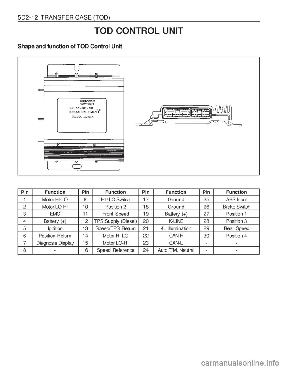
5D2-12 TRANSFER CASE (TOD)Pin1 2345 6 78
Function
Motor HI-LO Motor LO-HI EMC
Battery (+)
Ignition
Position Return
Diagnosis Display - Pin
9
10 11
1213 14 1516 Function
HI / LO Switch Position 2
Front Speed
TPS Supply (Diesel) Speed/TPS Return
Motor HI-LOMotor LO-HI
Speed Reference Pin
1718192021 22 2324 Function
GroundGround
Battery (+) K-LINE
4L Illumination
CAN-HCAN-L
Auto T/M, Neutral Pin
2526272829 30 - - Function ABS Input
Brake Switch
Position 1 Position 3
Rear Speed
Position 4 --
TOD CONTROL UNIT
Shape and function of TOD Control Unit
Page 1139 of 1574
5D2-50 TRANSFER CASE (TOD)
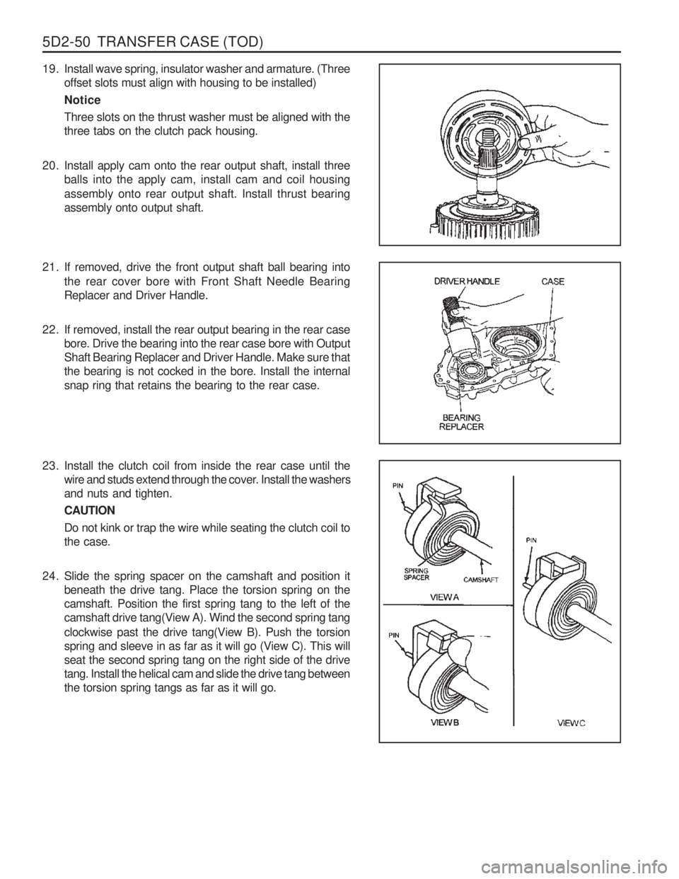
19. Install wave spring, insulator washer and armature. (Threeoffset slots must align with housing to be installed) NoticeThree slots on the thrust washer must be aligned with the three tabs on the clutch pack housing.
20. Install apply cam onto the rear output shaft, install three balls into the apply cam, install cam and coil housing assembly onto rear output shaft. Install thrust bearing assembly onto output shaft.
21. If removed, drive the front output shaft ball bearing into
the rear cover bore with Front Shaft Needle Bearing Replacer and Driver Handle.
22. If removed, install the rear output bearing in the rear case bore. Drive the bearing into the rear case bore with OutputShaft Bearing Replacer and Driver Handle. Make sure thatthe bearing is not cocked in the bore. Install the internalsnap ring that retains the bearing to the rear case.
23. Install the clutch coil from inside the rear case until the wire and studs extend through the cover. Install the washersand nuts and tighten. CAUTIONDo not kink or trap the wire while seating the clutch coil to the case.
24. Slide the spring spacer on the camshaft and position it beneath the drive tang. Place the torsion spring on thecamshaft. Position the first spring tang to the left of thecamshaft drive tang(View A). Wind the second spring tang clockwise past the drive tang(View B). Push the torsion spring and sleeve in as far as it will go (View C). This willseat the second spring tang on the right side of the drivetang. Install the helical cam and slide the drive tang betweenthe torsion spring tangs as far as it will go.
Page 1208 of 1574
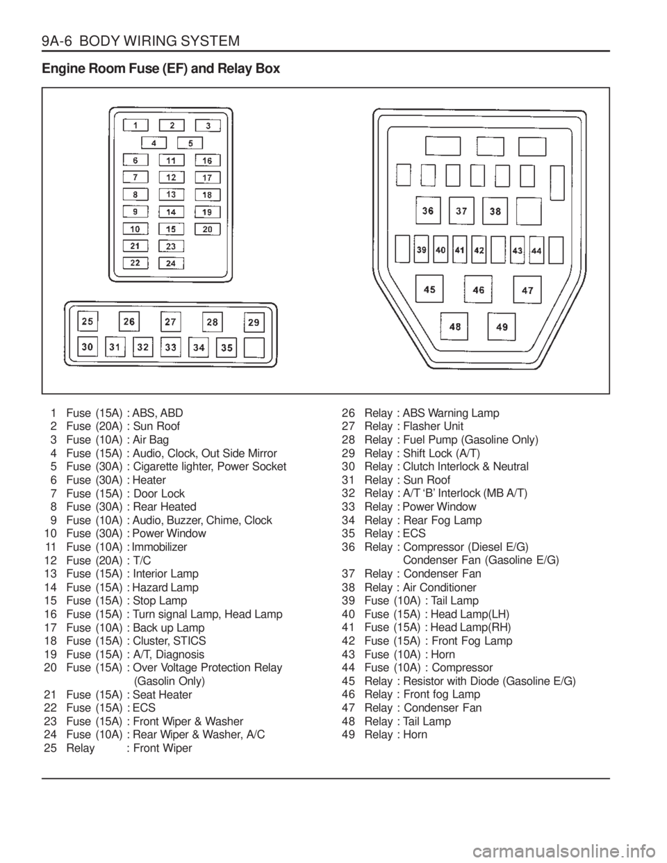
9A-6 BODY WIRING SYSTEM Engine Room Fuse (EF) and Relay Box1 Fuse (15A) : ABS, ABD
2 Fuse (20A) : Sun Roof
3 Fuse (10A) : Air Bag
4 Fuse (15A) : Audio, Clock, Out Side Mirror
5 Fuse (30A) : Cigarette lighter, Power Socket
6 Fuse (30A) : Heater
7 Fuse (15A) : Door Lock
8 Fuse (30A) : Rear Heated
9 Fuse (10A) : Audio, Buzzer, Chime, Clock
10 Fuse (30A) : Power Window
11 Fuse (10A) : Immobilizer
12 Fuse (20A) : T/C
13 Fuse (15A) : Interior Lamp
14 Fuse (15A) : Hazard Lamp
15 Fuse (15A) : Stop Lamp
16 Fuse (15A) : Turn signal Lamp, Head Lamp
17 Fuse (10A) : Back up Lamp
18 Fuse (15A) : Cluster, STICS
19 Fuse (15A) : A/T, Diagnosis
20 Fuse (15A) : Over Voltage Protection Relay (Gasolin Only)
21 Fuse (15A) : Seat Heater
22 Fuse (15A) : ECS
23 Fuse (15A) : Front Wiper & Washer
24 Fuse (10A) : Rear Wiper & Washer, A/C
25 Relay : Front Wiper 26 Relay : ABS Warning Lamp
27 Relay : Flasher Unit
28 Relay : Fuel Pump (Gasoline Only)
29 Relay : Shift Lock (A/T)
30 Relay : Clutch Interlock & Neutral
31 Relay : Sun Roof
32 Relay : A/T ‘B’ Interlock (MB A/T)
33 Relay : Power Window
34 Relay : Rear Fog Lamp
35 Relay : ECS
36 Relay : Compressor (Diesel E/G)
Condenser Fan (Gasoline E/G)
37 Relay : Condenser Fan
38 Relay : Air Conditioner
39 Fuse (10A) : Tail Lamp
40 Fuse (15A) : Head Lamp(LH)
41 Fuse (15A) : Head Lamp(RH)
42 Fuse (15A) : Front Fog Lamp
43 Fuse (10A) : Horn
44 Fuse (10A) : Compressor
45 Relay : Resistor with Diode (Gasoline E/G)
46 Relay : Front fog Lamp
47 Relay : Condenser Fan
48 Relay : Tail Lamp
49 Relay : Horn
Page 1210 of 1574
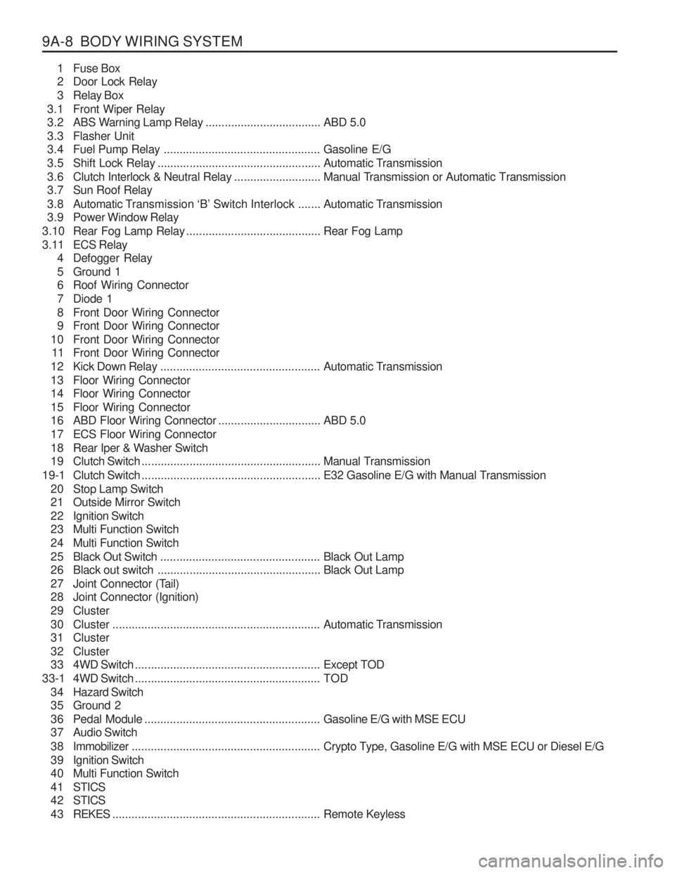
9A-8 BODY WIRING SYSTEM1 Fuse Box
2 Door Lock Relay
3 Relay Box
3.1 Front Wiper Relay
3.2 ABS Warning Lamp Relay ....................................ABD 5.0
3.3 Flasher Unit
3.4 Fuel Pump Relay ................................................. Gasoline E/G
3.5 Shift Lock Relay ................................................... Automatic Transmission
3.6 Clutch Interlock & Neutral Relay ...........................Manual Transmission or Automatic Transmission
3.7 Sun Roof Relay
3.8 Automatic T ransmission ‘B’ Switch Interlock ....... Automatic Transmission
3.9 Power Window Relay
3.10 Rear Fog Lamp Relay .......................................... Rear Fog Lamp
3.11 ECS Relay 4 Defogger Relay
5 Ground 1
6 Roof Wiring Connector
7 Diode 1
8 Front Door Wiring Connector
9 Front Door Wiring Connector
10 Front Door Wiring Connector 11 Front Door Wiring Connector
12 Kick Down Relay .................................................. Automatic Transmission
13 Floor Wiring Connector
14 Floor Wiring Connector
15 Floor Wiring Connector
16 ABD Floor Wiring Connector ................................ABD 5.0
17 ECS Floor Wiring Connector
18 Rear Iper & Washer Switch
19 Clutch Switch ........................................................ Manual Transmission
19-1 Clutch Switch ........................................................ E32 Gasoline E/G with Manual Transmission
20 Stop Lamp Switch
21 Outside Mirror Switch
22 Ignition Switch
23 Multi Function Switch
24 Multi Function Switch
25 Black Out Switch .................................................. Black Out Lamp
26 Black out switch ................................................... Black Out Lamp
27 Joint Connector (Tail)
28 Joint Connector (Ignition)
29 Cluster
30 Cluster ................................................................. Automatic Transmission
31 Cluster
32 Cluster
33 4WD Switch .......................................................... Except TOD
33-1 4WD Switch .......................................................... TOD
3 4 Hazard Switch
35 Ground 2
36 Pedal Module ....................................................... Gasoline E/G with MSE ECU
37 Audio Switch
3 8 Immobilizer ........................................................... Crypto Type, Gasoline E/G with MSE ECU or Diesel E/G
39 Ignition Switch
40 Multi Function Switch
4 1 STICS
4 2 STICS
4 3 REKES ................................................................. Remote Keyless