Page 801 of 1574
4A-4 HYDRAULIC BRAKES
COMPONENT LOCATOR
ABS
1 Actuation Assembly (Booster+TMC)
2 ABS Control Unit
3 Master Cylinder 2nd Tube (Secondary)
4 Master Cylinder 1st Tube (Primary)
5 Front Tube (LH)
6 Front Tube (RH) 7 Brake Hose
8 Rear Tube
9 Bolt
...................................................... 25-35 Nm
10 2-way Connector 11 3-way Connector
Page 802 of 1574
HYDRAULIC BRAKES 4A-5
ABS / ABD1 Actuation Assembly (Booster+TMC)
2 Master Cylinder 1st Tube (Primary)
3 Master Cylinder 2nd Tube (Secondary)
4 Hydraulic Modulator
5 Front Tube (LH) 6 Front Tube (RH)
7 Rear Tube (RH)
8 Rear Tube (LH)
9 2-way Connector
Page 803 of 1574
4A-6 HYDRAULIC BRAKES
NON-ABS/ABD1 Actuation Assembly (Booster+TMC)
2 3-way Connector
3 Front Tube (LH)
4 Front Tube (RH)
5 2-way Connector
6 Rear Tube
7 3-way Connector
8 LCRV
Page 823 of 1574
FRONT DISC BRAKES 4D-3
Removal & Installation Procedure
1. MANDO Brake
Tightening Torque 25 - 35 Nm
2. PBR Brake Remove the eye-hose bolt and disconnect the hose. Installation Notice
Tightening Torque 15 - 18 Nm
3. Remove the wheel speed sensor (for ABS vehicies). Installation Notice
Tightening Torque 6 - 8 Nm
4. Remove the mounting bolts and then caliper assembly. Installation Notice
Tightening Torque 85 - 105 Nm
Remove the hose mounting nut and disconnect the hose. Installation Notice
Page 830 of 1574

FrontRear
Front Rear
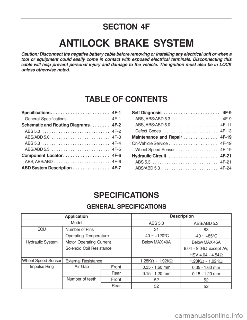
SECTION 4F
ANTILOCK BRAKE SYSTEM
TABLE OF CONTENTS
Caution: Disconnect the negative battery cable before removing or installing any electrical unit or when a tool or equipment could easily come in contact with exposed electrical terminals. Disconnecting thiscable will help prevent personal injury and damage to the vehicle. The ignition must also be in LOCKunless otherwise noted.
SPECIFICATIONS
GENERAL SPECIFICATIONS
Application Model
ECUNumber of Pins
Operating TemperatureMotor Operating CurrentSolenoid Coil Resistance External Resistance Air Gap
Number of teeth Description
ABS 5.3 31
-40 ~ +120 °C
Below MAX 40A
1.28K � - 1.92K �
0.35 - 1.60 mm 0.15 - 1.20 mm 52 52 ABS/ABD 5.3
83
-40 ~ +85 °C
Below MAX 45A
8.04 - 9.04 � except AV,
HSV 4.04 - 4.54 �
1.28K � - 1.92K �
0.35 - 1.60 mm 0.15 - 1.20 mm
52 52
Hydraulic System
Wheel Speed Sensor Impulse Ring
Specifications . . . . . . . . . . . . . . . . . . . . . . . . 4F-1
General Specifications . . . . . . . . . . . . . . . . . . 4F-1
Schematic and Routing Diagrams . . . . . . . . 4F-2 ABS 5.0 . . . . . . . . . . . . . . . . . . . . . . . . . . . . . 4F-2
ABS/ABD 5.0 . . . . . . . . . . . . . . . . . . . . . . . . . 4F-3
ABS 5.3 . . . . . . . . . . . . . . . . . . . . . . . . . . . . . 4F-4
ABS/ABD 5.3 . . . . . . . . . . . . . . . . . . . . . . . . . 4F-5
Component Locator . . . . . . . . . . . . . . . . . . . 4F-6 ABS, ABS/ABD . . . . . . . . . . . . . . . . . . . . . . . . 4F-6
ABD System Description . . . . . . . . . . . . . . . 4F-7 Self Diagnosis . . . . . . . . . . . . . . . . . . . . . . . 4F-9
ABS, ABS/ABD 5.3 . . . . . . . . . . . . . . . . . . . . . 4F-9
ABS, ABS/ABD 5.0 . . . . . . . . . . . . . . . . . . . . 4F-11
Defect Codes . . . . . . . . . . . . . . . . . . . . . . . . 4F-13
Maintenance and Repair . . . . . . . . . . . . . . 4F-19
On-Vehicle Service . . . . . . . . . . . . . . . . . . . . 4F-19
Wheel Speed Sensor . . . . . . . . . . . . . . . . . . 4F-19
Hydraulic Circuit . . . . . . . . . . . . . . . . . . . . 4F-21 ABS 5.3 . . . . . . . . . . . . . . . . . . . . . . . . . . . . 4F-21
ABS/ABD 5.3 . . . . . . . . . . . . . . . . . . . . . . . . 4F-24
Page 831 of 1574
4F-2 ANTILOCK BRAKE SYSTEM
ABS 5.0
SCHEMATIC AND ROUTING DIAGRAMS
5.0W5.0W
30A
30A
ENG
Page 832 of 1574
ANTILOCK BRAKE SYSTEM 4F-3
ABS/ABD 5.0
ABD ACTIVE
Page 833 of 1574
4F-4 ANTILOCK BRAKE SYSTEM
ABS 5.3
5.0W5.0W
30A
30A
NO.21
K2