Page 266 of 1574

SECTION 1B3
OM600 ENGINE MECHANICAL
CAUTION: Disconnect the negative battery cable before removing or installing any electrical unit or when a tool or equipment could easily come in contact with exposed electrical terminals. Disconnecting this cable will help prevent personal injury and damage to the vehicle. The ignition must also be in LOCK unless otherwisenoted.
Specifications . . . . . . . . . . . . . . . . . . . . . . . 1B3-2Fastener Tightening Specifications . . . . . . . . 1B3-2
Special Tools . . . . . . . . . . . . . . . . . . . . . . . 1B3-4 Special Tools Table . . . . . . . . . . . . . . . . . . . . 1B3-4
Maintenance and Repair . . . . . . . . . . . . . 1B3-12
On-Vehicle Service . . . . . . . . . . . . . . . . . . . . 1B3-12
Engine Assembly . . . . . . . . . . . . . . . . . . . . 1B3-12
Poly V-Belt . . . . . . . . . . . . . . . . . . . . . . . . . 1B3-21
Tensioning Device . . . . . . . . . . . . . . . . . . . . 1B3-23
Poly V-Belt Alignment & Inspection . . . . . . . 1B3-26
Prechamber . . . . . . . . . . . . . . . . . . . . . . . . 1B3-29
Milling of Prechamber Sealing Surface . . . . 1B3-32
TDC (TDC Sensor Bracket) Setting . . . . . . 1B3-35
Cylinder Head . . . . . . . . . . . . . . . . . . . . . . . 1B3-37
Timing Case Cover . . . . . . . . . . . . . . . . . . . 1B3-63
Crankshaft End Cover . . . . . . . . . . . . . . . . 1B3-71
Vibration Damper and Hub . . . . . . . . . . . . . 1B3-74
Crankshaft Front Radial Seal . . . . . . . . . . . 1B3-80
Crankshaft Ball Bearing . . . . . . . . . . . . . . . 1B3-82
Crankshaft . . . . . . . . . . . . . . . . . . . . . . . . . 1B3-83
Flywheel . . . . . . . . . . . . . . . . . . . . . . . . . . . 1B3-93
Machining of Flywheel . . . . . . . . . . . . . . . . 1B3-97
Flywheel Ring Gear . . . . . . . . . . . . . . . . . . 1B3-98
Hydraulic Valve Clearance Compensation
Element Check . . . . . . . . . . . . . . . . . . . . 1B3-101
Valve Tappets . . . . . . . . . . . . . . . . . . . . . . 1B3-103
Valve Spring Check . . . . . . . . . . . . . . . . . 1B3-105
Valve Springs (Cylinder Head Removed) . 1B3-106
TABLE OF CONTENTS
Valve Springs (Cylinder Head Installed) . . 1B3-109
Valve Stem Seals . . . . . . . . . . . . . . . . . . . 1B3-112
Check and Replacement of Valve Guides . . . . . . . . . . . . . . . . . . . . . 1B3-116
Valve Seat Rings . . . . . . . . . . . . . . . . . . . 1B3-122
Check and Machining of Valves . . . . . . . . 1B3-127
Machining of Valve Seat . . . . . . . . . . . . . . 1B3-132
Camshaft Timing Test . . . . . . . . . . . . . . . . 1B3-137
Camshaft . . . . . . . . . . . . . . . . . . . . . . . . . 1B3-139
Chain Tensioner . . . . . . . . . . . . . . . . . . . . 1B3-145
Timing Chain . . . . . . . . . . . . . . . . . . . . . . . 1B3-147
Tensioning Rail . . . . . . . . . . . . . . . . . . . . . 1B3-151
Cylinder Head Guide Rail . . . . . . . . . . . . . 1B3-152
Timing Case Cover Guide Rail . . . . . . . . . 1B3-156
Crankshaft Sprocket . . . . . . . . . . . . . . . . . 1B3-158
Piston . . . . . . . . . . . . . . . . . . . . . . . . . . . . 1B3-163
Oil Filter . . . . . . . . . . . . . . . . . . . . . . . . . . 1B3-169
Oil Pan . . . . . . . . . . . . . . . . . . . . . . . . . . . 1B3-171
Oil Spray Nozzle . . . . . . . . . . . . . . . . . . . . 1B3-174
Oil Pump . . . . . . . . . . . . . . . . . . . . . . . . . . 1B3-175
Unit Repair . . . . . . . . . . . . . . . . . . . . . . . 1B3-177
Cylinder Head Pressure Leakage Test . . . 1B3-177
Facing Cylinder Head Mating Surface . . . . 1B3-178
Replacement of Crankcase Core Plug . . . 1B3-180
Facing Crankcase Contacting Surface . . . 1B3-182
Oil Gallery Steel Ball . . . . . . . . . . . . . . . . . 1B3-183
Cylinder Bore Measurement . . . . . . . . . . . 1B3-187
Page 269 of 1574
1B3-4 OM600 ENGINE MECHANICALSPECIAL TOOLS
SPECIAL TOOLS TABLE
603 589 00 09 00
Serration Wrench
657 589 03 63 00
Sliding Hammer 000 589 77 03 00
Box Wrench Insert
601 589 00 66 00 Counter Sink
667 589 00 23 00 Height Gauge 602 589 00 40 00
Engine Lock
116 589 20 33 00
Sliding Hammer 603 589 00 40 00
Counter Holder
Page 278 of 1574
OM600 ENGINE MECHANICAL 1B3-13
4. Remove the radiator drain cock and drain the coolant.Notice Open the coolant reservoir tank cap.
3. Remove the skid plate.
Installation Notice
Tightening Torque 28 - 47 Nm
5. Remove the drain plug (1) and seal (2) from the cylinder block and drain the coolant completely.
6. After draining, replace the seal and reinstall the drain plug.
Installation Notice
7. Disconnect the lower coolant hose from the radiator.
Tightening Torque 30 Nm
Removal & Installation Procedure
1. Disconnect the negative terminal of battery.
2. Remove the hood.
Page 301 of 1574

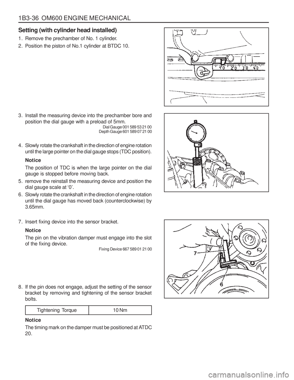
1B3-36 OM600 ENGINE MECHANICAL Setting (with cylinder head installed)
1. Remove the prechamber of No. 1 cylinder.
2. Position the piston of No.1 cylinder at BTDC 10.
3. Install the measuring device into the prechamber bore andposition the dial gauge with a preload of 5mm. Dial Gauge 001 589 53 21 00
Depth Gauge 601 589 07 21 00
4. Slowly rotate the crankshaft in the direction of engine rotation until the large pointer on the dial gauge stops (TDC position). Notice The position of TDC is when the large pointer on the dial gauge is stopped before moving back.
5. remove the reinstall the measuring device and position the dial gauge scale at ‘0’.
6. Slowly rotate the crankshaft in the direction of engine rotation until the dial gauge has moved back (counterclockwise) by3.65mm.
7. Insert fixing device into the sensor bracket. Notice The pin on the vibration damper must engage into the slot of the fixing device. Fixing Device 667 589 01 21 00
8. If the pin does not engage, adjust the setting of the sensor bracket by removing and tightening of the sensor bracketbolts.
Tightening Torque 10 Nm
Notice
The timing mark on the damper must be positioned at ATDC 20.
Page 303 of 1574
1B3-38 OM600 ENGINE MECHANICAL
000 589 77 03 00 Box Wrench Insert
001 589 65 09 00 Socket Wrench Insert
102 589 03 40 00 Magnetic Bar
116 589 02 34 00 Threaded Pin
116 589 03 07 00 T Type Socket Wrench
116 589 20 33 00 Sliding Hammer
601 589 00 10 00 Cylinder Head Bolt Wrench
602 589 00 40 00 Engine Lock
603 589 00 40 00 Counter Holder
Tools Required
Cylinder Bolts (12-sided socket head) (Engine cold) M8 Cylinder Head Bolts
Tightening Torque
stage1 stage2stage3
10 Nm35 Nm
180 °
25 Nm
Tightening Sequence for Cylinder Head Bolts OM 662LA Engine
OM 661LA Engine
Page 305 of 1574
1B3-40 OM600 ENGINE MECHANICAL Disassembly Procedure
1. Completely drain the coolant from the radiator and cylinderblock.
2. Remove the cooling fan shroud.
3. Hold the fan with counter holder and remove the bolt and then remove the cooling fan. Notice Keep the fan in vertical position.
Counter Holder 603 589 00 40 00
5. Remove the nut.
6. Remove the nut on the tensioning lever and insert therod(F12 ´ 180mm). By pushing the rod to the arrow direction,
pull back the bolt.
7. Push the tensioning lever to the opposite direction to release the spring tension and remove the poly V-belt.
4. Remove the bracket oil dipstick tube.
Page 311 of 1574
1B3-46 OM600 ENGINE MECHANICAL
30. Rotate the crankshaft and set the no.1 cylinder at TDC.Notice Do not rotate the crankshaft to the opposite direction of engine revolution.
31. Place alignment marks on the camshaft gear and timing chain.
32. Ensure that the camshaft and the bearing cap marking are aligned.
33. Remove the starter motor and install the engine lock onto the flywheel ring gear.
Engine Lock 602 589 00 40 00
Page 313 of 1574
1B3-48 OM600 ENGINE MECHANICAL
38. Remove the camshaft bearing cap bolts according to thenumerical sequence. Notice Remove the No.1 bolts first and then remove the No. 2 bolts. Do not remove the bolts at a time completely butremove them step by step evenly or camshaft can beseriously damaged.
OM662LA
39. Remove the bearing caps and then pull out the camshaft(20) upward. Notice
Be careful not to miss the locking washer.
40. Remove the locking washer. Notice
Check the locking washer and replace if necessary.
OM661LA