Page 1164 of 1574
7D-8 FATC-HAVC Self-diagnosis Method
Ignition switch “ON ”
Press the intake switch more than 4 times within
2 seconds while pressing the AUTO switch
Self-diagnosis will start after turning off all displays on VFD for 2.5 seconds
Self-diagnosis items check (continuous action)
Airconditioner control
Self-diagnosis items check
(step action)
Press AUTO Press AUTO Press OFF
Press OFF
DIAGNOSIS TEST
FATC airconditioner system has self-diagnosis function.
Turn the ignition switch ON and press intake switch more than 4 times within 2 seconds while the AUTO switch is
1 AUTO Switch
2 Intake Switch
3 OFF Switch 4 Airconditioner Switch
5 Set temperature Display
pressed, then it will diagnose incar sensor, ambient
sensor, water temperature sensor and temperature actuator for open/short and will display numerical fault code on the set temperature display of VFD.
DIAGNOSIS
Page 1165 of 1574

FATC-HAVC 7D-9
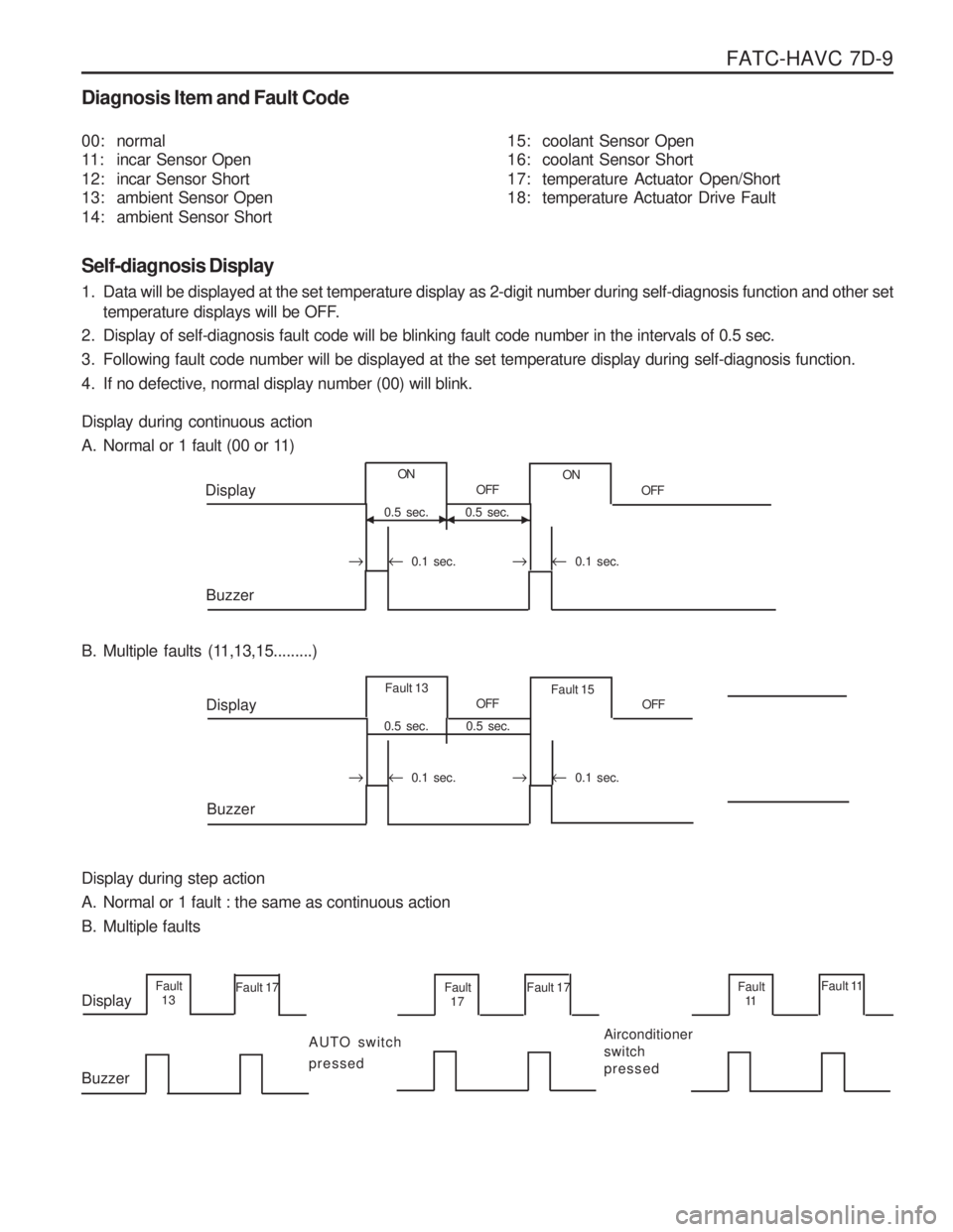
Diagnosis Item and Fault Code Self-diagnosis Display
1. Data will be displayed at the set temperature display as 2-digit number during self-diagnosis function and other settemperature displays will be OFF.
2. Display of self-diagnosis fault code will be blinking fault code number in the intervals of 0.5 sec.
3. Following fault code number will be displayed at the set temperature display during self-diagnosis function.
4. If no defective, normal display number (00) will blink. Display during continuous action
A. Normal or 1 fault (00 or 11) 15: coolant Sensor Open
16: coolant Sensor Short
17: temperature Actuator Open/Short
18: temperature Actuator Drive Fault
00: normal
11: incar Sensor Open
12: incar Sensor Short
13: ambient Sensor Open
14: ambient Sensor Short
B. Multiple faults (11,13,15.........) Display during step action
A. Normal or 1 fault : the same as continuous action
B. Multiple faults
�
0.1 sec. 0.1 sec.
0.5 sec.
ON
0.5 sec.OFF
ON
OFF
Display
Buzzer
0.5 sec.Fault 13
0.5 sec.OFF
Fault 15
OFF
Display
Buzzer
Fault 13 Fault 17
Display Buzzer AUTO switch pressedFault
17 Fault 17
Airconditioner switchpressedFault11 Fault 11
��
�
� 0.1 sec. 0.1 sec.
�� �
Page 1167 of 1574
FATC-HAVC 7D-11
1 AUTO Switch
2 MODE Switch
3 OFF Switch
4 Temperature UP/DOWN Switch
5 Defrost Switch6 Airconditioner Switch
7 Recirculation
fresh Air Switch
8 Blower Switch (UP/DOWN)
9 VFD (Vacuum Fluorescent Display)
MAINTENANCE AND REPAIR
FATC CONTROL PANEL Components
Page 1187 of 1574

SUPPLEMENTAL RESTRAINT SYSTEM(SRS) 8B-7
DIAGNOSIS
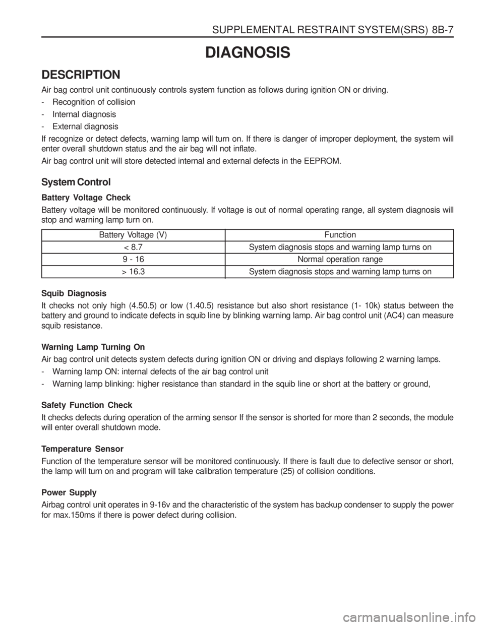
DESCRIPTION Air bag control unit continuously controls system function as follows during ignition ON or driving.
- Recognition of collision
- Internal diagnosis
- External diagnosisIf recognize or detect defects, warning lamp will turn on. If there is danger of improper deployment, the system will enter overall shutdown status and the air bag will not inflate. Air bag control unit will store detected internal and external defects in the EEPROM. System Control
Battery Voltage Check
Battery voltage will be monitored continuously. If voltage is out of normal operating range, all system diagnosis will stop and warning lamp turn on. Battery Voltage (V)< 8.7
9 - 16
> 16.3
Function
System diagnosis stops and warning lamp turns on Normal operation range
System diagnosis stops and warning lamp turns on
Squib Diagnosis It checks not only high (4.50.5) or low (1.40.5) resistance but also short resistance (1- 10k) status between the battery and ground to indicate defects in squib line by blinking warning lamp. Air bag control unit (AC4) can measure squib resistance.
Warning Lamp Turning On Air bag control unit detects system defects during ignition ON or driving and displays following 2 warning lamps.
- Warning lamp ON: internal defects of the air bag control unit
- Warning lamp blinking: higher resistance than standard in the squib line or short at the battery or ground, Safety Function Check It checks defects during operation of the arming sensor If the sensor is shorted for more than 2 seconds, the module will enter overall shutdown mode.
Temperature Sensor
Function of the temperature sensor will be monitored continuously. If there is fault due to defective sensor or short, the lamp will turn on and program will take calibration temperature (25) of collision conditions. Power Supply Airbag control unit operates in 9-16v and the characteristic of the system has backup condenser to supply the power for max.150ms if there is power defect during collision.
Page 1190 of 1574
8B-10 SUPPLEMENTAL RESTRAINT SYSTEM(SRS)
1. Position the ignition switch to ‘OFF’.
2. Connect the harness connector of scanner to the diagnosissocket in engine compartment.
3. Turn the ignition switch to ‘ON’ position.
4. Select “Electronic control vehicle diagnosis” from function selection display and press ‘Enter’ .
5. Select “Musso (’98 model year)” from vehicle model selection display and press ‘Enter’ .
6. Select “Electronic air bag” from control system selection display and press ‘Enter’ .
7. Select “Self-diagnosis” from diagnosis item selection display.
Notice
Check sensor value of output display, if necessary.
8. Determine the fault code and trace defective component.
NoticeRefer to self-diagnosis list.
SELF DIAGNOSIS
Page:
< prev 1-8 9-16 17-24