Page 651 of 1574
OM600 ENGINE CONTROLS 1F3-41
With Pulse Generator
Tools Required 617 589 09 21 00 Rl Sensor
617 589 10 21 00 Timing Tester667 589 00 21 00 TDC Pulse Generator
Commercial Tools
Item
Digital Tester
Without Pulse Generator Tools
Bosch, MOT 001.03
Hartmann & Braun, EOMT3 Bosch, ETD 019.00Sun, DIT 9000
ALV, Diesel - Tester 875
Test Procedure
1. Remove the screw plug (7) and seal (8) collect oil in a suitable vessel.
2. Install the Rl sensor into the governor housing of injection pump (1).
Rl Sensor 617 589 10 21 00
3. Connect the digital tester and TDC pulse sender unit according to connection diagram.
4. Run the engine at idle speed and check the Rl value on the digital tester Notice
If out of standard, adjust the start of delivery.
5. Stop the engine.
6. Remove the Rl sensor, digital tester and TDC pulse sender unit.
7. Replace the seal and tighten the plug.
8. Check engine oil level and adjust if necessary.
Rl value A TDC 14° - 16 °
Tightening Torque 30 Nm
Page 656 of 1574
1F3-46 OM600 ENGINE CONTROLS
Tools Required 000 589 77 03 00 Box Wrench Insert 601 589 00 08 00 Flange 601 589 05 21 00 Locking Screw601 589 05 14 00 Assembly CageRemoval
FUEL INJECTION PUMP
Preceding Work : Removal of vacuum pump
Removal of air cleaner housing Removal of intake manifold
18 Chain Tensioner ......................................... 80Nm
19 Seal ....................................................... Replace
20 Bolt(Left-Hand Thread) ..............................46Nm
21 Washer
22 Bolt ............................................................ 23Nm
23 Seal ....................................................... Replace 24 Oil Pan
25 Fuel Injection Pump
26 Seal
....................................................... Replace
27 Screw Plug ................................................. 30Nm
28 Square Nut
Page 659 of 1574
OM600 ENGINE CONTROLS 1F3-49
Installation Procedure
1. Remove the screw plug (27) and seal (26) and collect oil ina vessel.
2. Insert flange (31) onto the injection pump camshaft and turn until the cam of the governor is visible in the hole.
Flange 601 589 00 08 00
3. Tighten the locking screw. Locking Screw 601 589 05 21 00
4. Ensure that the No.1 cylinder is positioned at A TDC 15°.
Page 660 of 1574
1F3-50 OM600 ENGINE CONTROLS
10. Connect the fuel pipesNotice Replace the seal. Box Wrench Insert 000 589 77 03 00
Return Line Fuel Injection LineFuel feed LineSuction and Pressure Line 46 Nm18 Nm13 Nm13 Nm
5. Coat the new seal (23) with engine oil and install it.
6. Insert the fuel injection pump (25) and tighten the bolts
(22).
7. Remove the locking screw (32).
Tightening Torque 23 Nm
8. Tighten the bolt(12).
9. Insert the washer (21) and tighten the bolts (20) and then remove the assembly cage (29).
Tightening Torque 23 Nm
Tightening Torque 46 Nm
Page 692 of 1574
1G3-8 OM600 ENGINE INTAKE & EXHAUST
1 Turbocharger Oil Inlet
2 Turbine Wheel
3 Waste Gate
4 Oil Outlet
5 Compressor Wheel6 Air Inlet
7 Exhaust Gas Outlet
8 Compressed Air Flow
9 Intercooler
10 Cylinder
TURBOCHARGER
CHARGE AIR SYSTEM DIAGRAM
Page 695 of 1574
OM600 ENGINE INTAKE & EXHAUST 1G3-11
TURBOCHARGER ASSEMBLY
1 Oil Supply Line
2 Oil Return Line3 Nuts
4 Turbocharger
Page 696 of 1574
1G3-12 OM600 ENGINE INTAKE & EXHAUST
Removal & Installation Procedure
1. Remove the 2 hoses connected to intercooler.
2. Remove the hose(air cleaner to turbocharger) with blow byhose.
3. Disconnect the oil supply pipe.
4. Remove the oil return pipe.
5. Remove the support assembly.
6. Remove the 3 nuts(arrows).
Page 700 of 1574

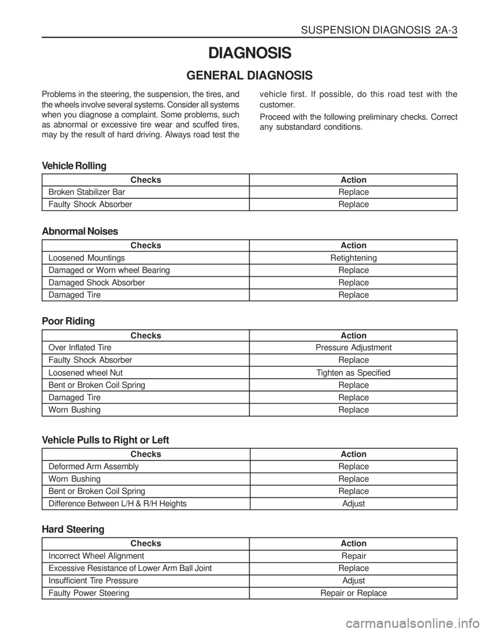
SUSPENSION DIAGNOSIS 2A-3
DIAGNOSIS
GENERAL DIAGNOSIS
Checks
Loosened Mountings Damaged or Worn wheel BearingDamaged Shock Absorber
Damaged Tire Action
Retightening ReplaceReplaceReplace
Abnormal Noises
Checks
Broken Stabilizer Bar Faulty Shock Absorber Action
ReplaceReplace
Vehicle Rolling
Checks
Over Inflated Tire Faulty Shock Absorber Loosened wheel Nut Bent or Broken Coil Spring
Damaged TireWorn Bushing Action
Pressure Adjustment
Replace
Tighten as Specified ReplaceReplaceReplace
Poor Riding
Problems in the steering, the suspension, the tires, and the wheels involve several systems. Consider all systems when you diagnose a complaint. Some problems, suchas abnormal or excessive tire wear and scuffed tires,may by the result of hard driving. Always road test the
vehicle first. If possible, do this road test with the
customer. Proceed with the following preliminary checks. Correct any substandard conditions.
Checks
Incorrect Wheel Alignment Excessive Resistance of Lower Arm Ball Joint
Insufficient Tire PressureFaulty Power Steering
Action Repair
Replace Adjust
Repair or Replace
Hard Steering
Checks
Deformed Arm Assembly Worn BushingBent or Broken Coil SpringDifference Between L/H & R/H Heights Action
ReplaceReplaceReplace Adjust
Vehicle Pulls to Right or Left