Page 1124 of 1574
TRANSFER CASE (TOD) 5D2-35
Removal & Installation Procedure1. Disconnect (-) cable from battery.
2. Lift on vehicle and make sure on safety. NoticeBe careful for catalytic converter due to high temperature after driving or engine running.
3. Prepare a vessel to drain transfer case and manual transmission oil.
4. Release drain plug and drain transfer case and manual transmission oil. If planar damper is installed, unscrew 4 bolts and remove
the planar damper. NoticeOil drain should be along with whole transfer case
disassembly and assembly.
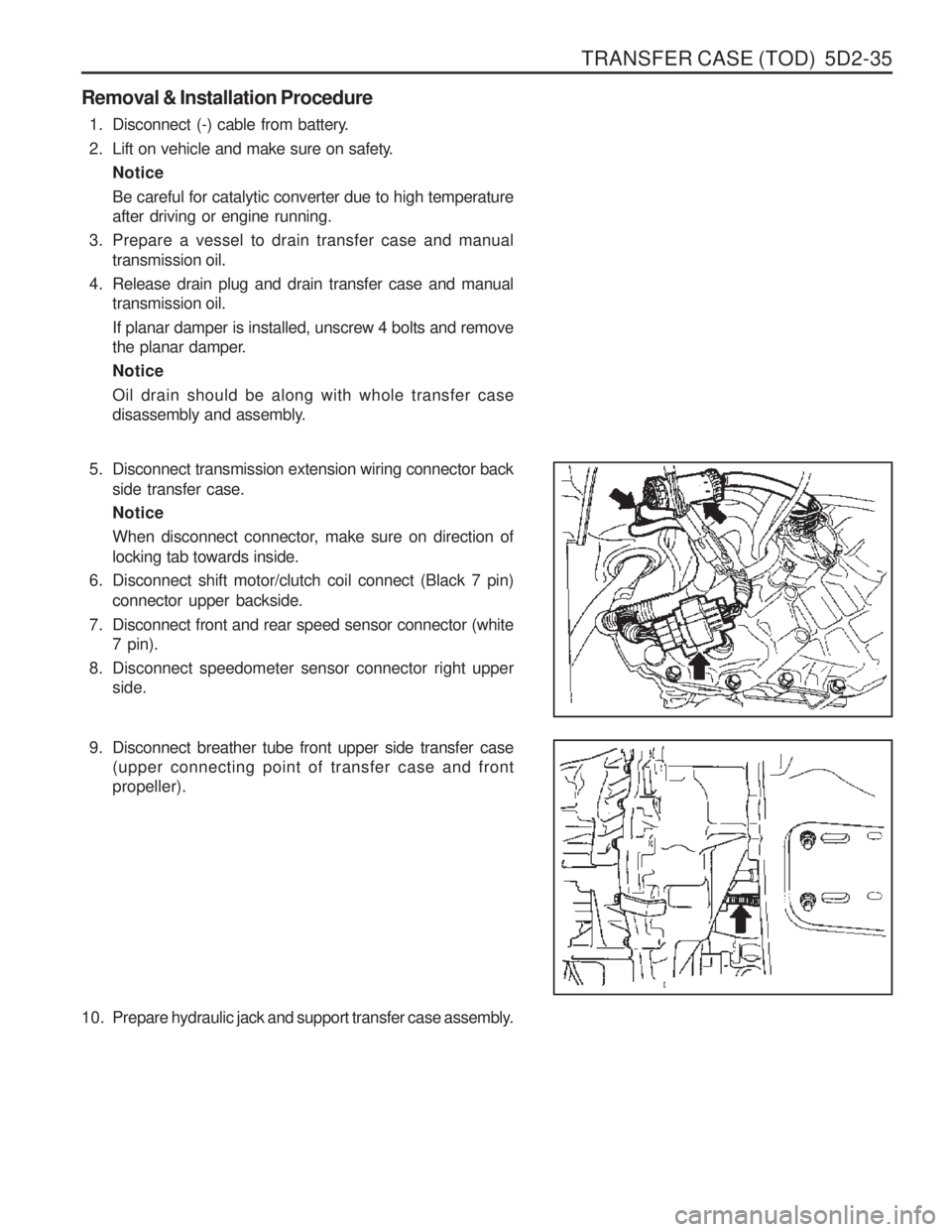
5. Disconnect transmission extension wiring connector back
side transfer case. Notice
When disconnect connector, make sure on direction of locking tab towards inside.
6. Disconnect shift motor/clutch coil connect (Black 7 pin) connector upper backside.
7. Disconnect front and rear speed sensor connector (white 7 pin).
8. Disconnect speedometer sensor connector right upper side.
9. Disconnect breather tube front upper side transfer case (upper connecting point of transfer case and front propeller).
10. Prepare hydraulic jack and support transfer case assembly.
Page 1127 of 1574
5D2-38 TRANSFER CASE (TOD)
SPEED SENSOR IN FRONT AND REAR PROPELLER SHAFT Replacement Procedure
1. Disconnect (-) cable from battery.
2. Detach shift motor assembly.
3. Disconnect front and rear speed sensor connector (white 3pin) upper backside transfer case.
4. Disconnect speed sensor connect from locking sleeve by pushing.
5. Disconnect wire stick cap from the detached connector.
6. Unscrew rear speed sensor mounting bolt (M10) from upper side of rear case flange.
7. Detach sensor from transfer case by lifting up using tool. Notice
When disconnect sensor, make sure on adequate pressure due to sensitiveness with shock.
8. Disconnect taping from both protection tube ends that wrap 3 wires of speed sensor and 1 wire of clutch coil.
9. Disconnect tube.
Page 1128 of 1574
TRANSFER CASE (TOD) 5D2-39
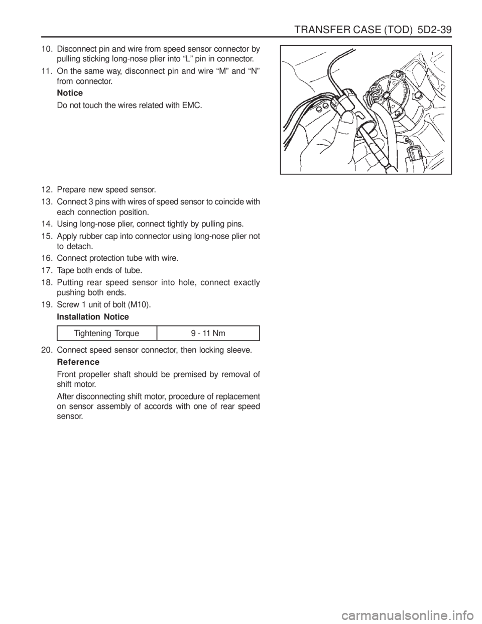
10. Disconnect pin and wire from speed sensor connector bypulling sticking long-nose plier into “L” pin in connector.
11. On the same way, disconnect pin and wire “M” and “N”
from connector. Notice Do not touch the wires related with EMC.
12. Prepare new speed sensor.
13. Connect 3 pins with wires of speed sensor to coincide with each connection position.
14. Using long-nose plier, connect tightly by pulling pins.
15. Apply rubber cap into connector using long-nose plier not to detach.
16. Connect protection tube with wire.
17. Tape both ends of tube.
18. Putting rear speed sensor into hole, connect exactly pushing both ends.
19. Screw 1 unit of bolt (M10). Installation Notice
Tightening Torque 9 - 11 Nm
20. Connect speed sensor connector, then locking sleeve. Reference Front propeller shaft should be premised by removal of
shift motor.
After disconnecting shift motor, procedure of replacement on sensor assembly of accords with one of rear speed
sensor.
Page 1137 of 1574
5D2-48 TRANSFER CASE (TOD)
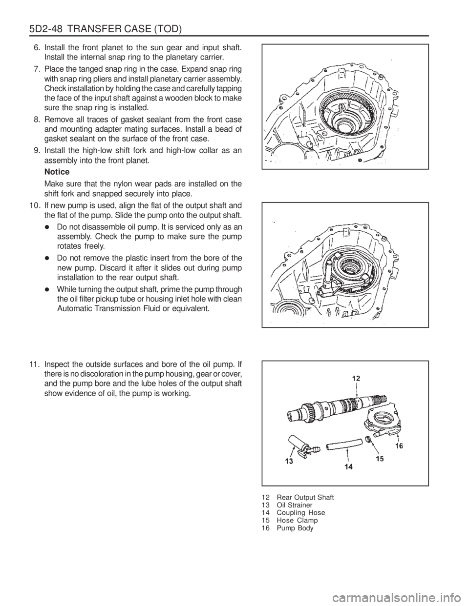
6. Install the front planet to the sun gear and input shaft.Install the internal snap ring to the planetary carrier.
7. Place the tanged snap ring in the case. Expand snap ring with snap ring pliers and install planetary carrier assembly. Check installation by holding the case and carefully tappingthe face of the input shaft against a wooden block to makesure the snap ring is installed.
8. Remove all traces of gasket sealant from the front case and mounting adapter mating surfaces. Install a bead ofgasket sealant on the surface of the front case.
9. Install the high-low shift fork and high-low collar as an assembly into the front planet. Notice Make sure that the nylon wear pads are installed on the shift fork and snapped securely into place.
12 Rear Output Shaft
13 Oil Strainer
14 Coupling Hose
15 Hose Clamp
16 Pump Body
10. If new pump is used, align the flat of the output shaft and
the flat of the pump. Slide the pump onto the output shaft.
�Do not disassemble oil pump. It is serviced only as an
assembly. Check the pump to make sure the pump
rotates freely.
� Do not remove the plastic insert from the bore of the
new pump. Discard it after it slides out during pumpinstallation to the rear output shaft.
� While turning the output shaft, prime the pump through
the oil filter pickup tube or housing inlet hole with clean
Automatic Transmission Fluid or equivalent.
11. Inspect the outside surfaces and bore of the oil pump. If there is no discoloration in the pump housing, gear or cover,and the pump bore and the lube holes of the output shaft show evidence of oil, the pump is working.
Page 1139 of 1574
5D2-50 TRANSFER CASE (TOD)
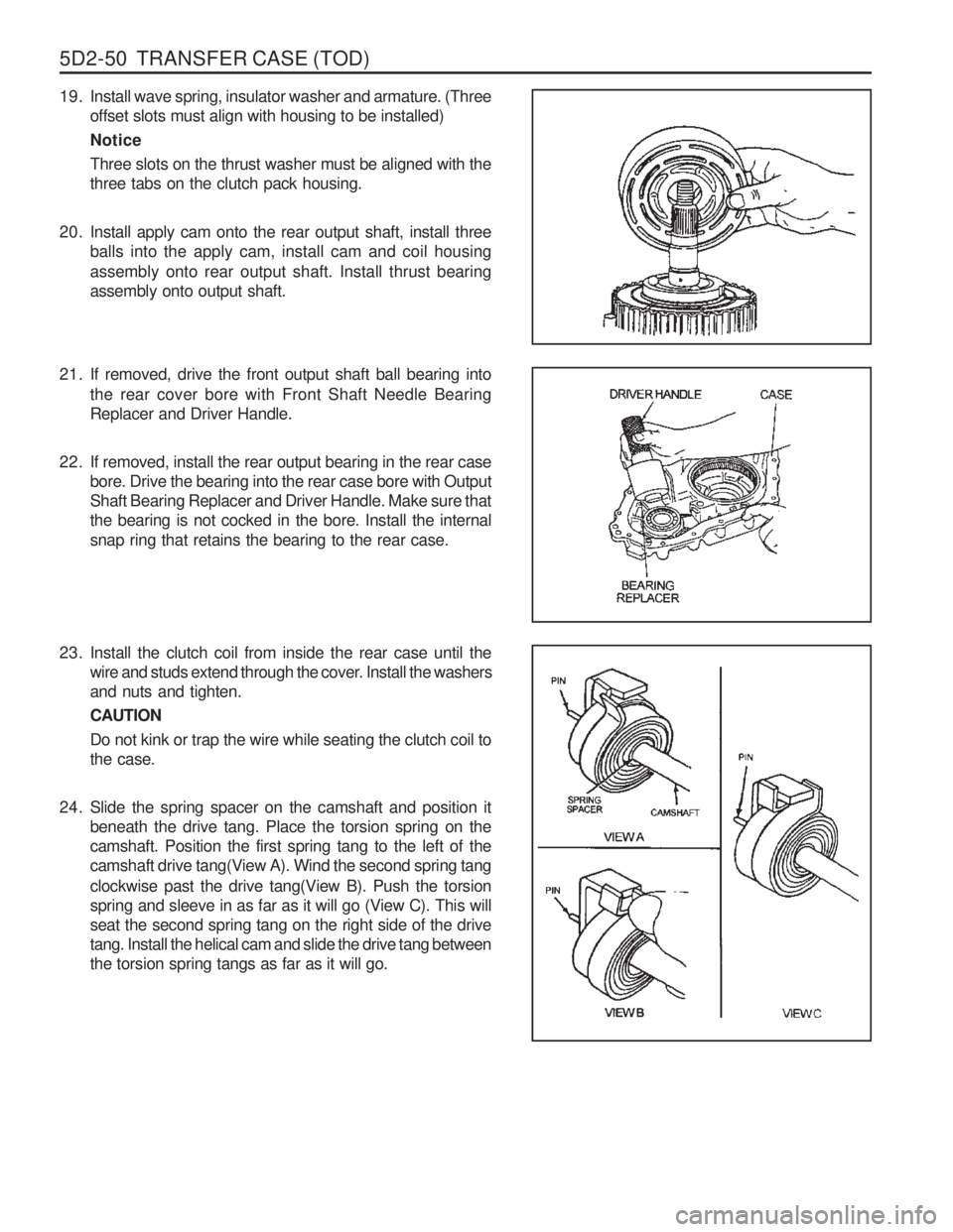
19. Install wave spring, insulator washer and armature. (Threeoffset slots must align with housing to be installed) NoticeThree slots on the thrust washer must be aligned with the three tabs on the clutch pack housing.
20. Install apply cam onto the rear output shaft, install three balls into the apply cam, install cam and coil housing assembly onto rear output shaft. Install thrust bearing assembly onto output shaft.
21. If removed, drive the front output shaft ball bearing into
the rear cover bore with Front Shaft Needle Bearing Replacer and Driver Handle.
22. If removed, install the rear output bearing in the rear case bore. Drive the bearing into the rear case bore with OutputShaft Bearing Replacer and Driver Handle. Make sure thatthe bearing is not cocked in the bore. Install the internalsnap ring that retains the bearing to the rear case.
23. Install the clutch coil from inside the rear case until the wire and studs extend through the cover. Install the washersand nuts and tighten. CAUTIONDo not kink or trap the wire while seating the clutch coil to the case.
24. Slide the spring spacer on the camshaft and position it beneath the drive tang. Place the torsion spring on thecamshaft. Position the first spring tang to the left of thecamshaft drive tang(View A). Wind the second spring tang clockwise past the drive tang(View B). Push the torsion spring and sleeve in as far as it will go (View C). This willseat the second spring tang on the right side of the drivetang. Install the helical cam and slide the drive tang betweenthe torsion spring tangs as far as it will go.
Page 1141 of 1574
5D2-52 TRANSFER CASE (TOD)
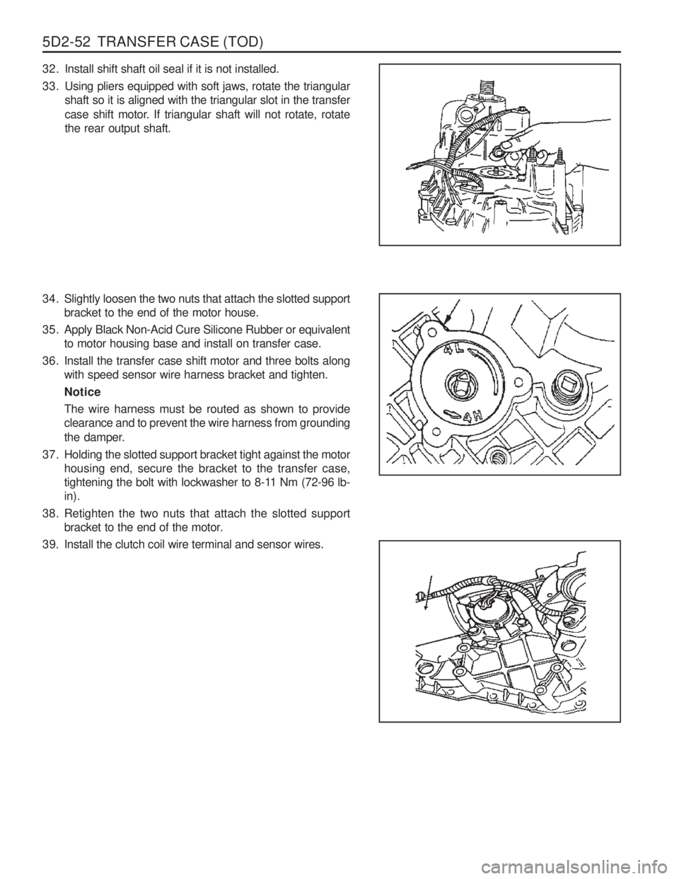
32. Install shift shaft oil seal if it is not installed.
33. Using pliers equipped with soft jaws, rotate the triangularshaft so it is aligned with the triangular slot in the transfer
case shift motor. If triangular shaft will not rotate, rotate the rear output shaft.
34. Slightly loosen the two nuts that attach the slotted support bracket to the end of the motor house.
35. Apply Black Non-Acid Cure Silicone Rubber or equivalent to motor housing base and install on transfer case.
36. Install the transfer case shift motor and three bolts along with speed sensor wire harness bracket and tighten. NoticeThe wire harness must be routed as shown to provide clearance and to prevent the wire harness from grounding
the damper.
37. Holding the slotted support bracket tight against the motor housing end, secure the bracket to the transfer case,
tightening the bolt with lockwasher to 8-11 Nm (72-96 lb-in).
38. Retighten the two nuts that attach the slotted support bracket to the end of the motor.
39. Install the clutch coil wire terminal and sensor wires.
Page 1148 of 1574
6A-6 POWER STEERING SYSTEM
OIL PUMP PRESSURE CHECK Oil Pump Pressure Check
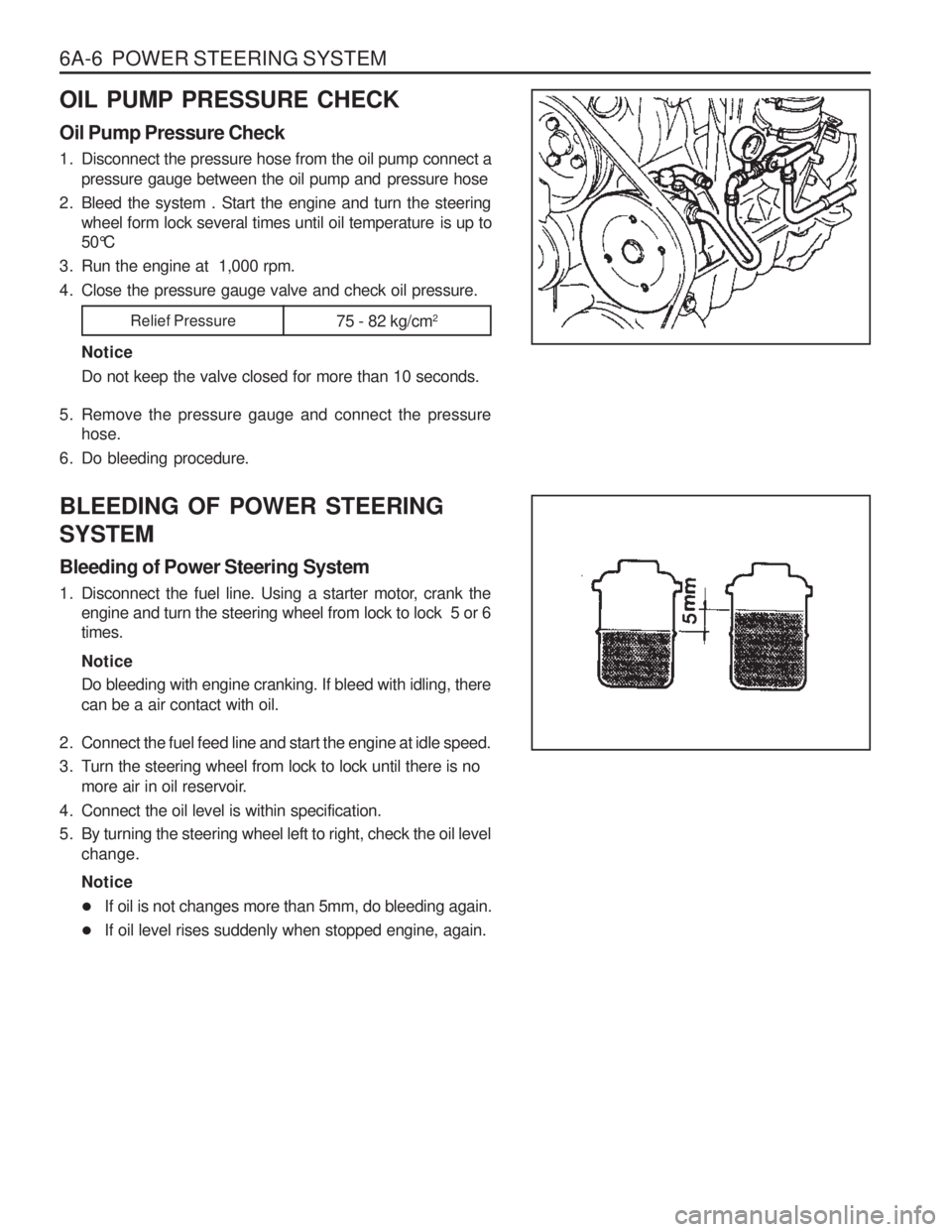
1. Disconnect the pressure hose from the oil pump connect apressure gauge between the oil pump and pressure hose
2. Bleed the system . Start the engine and turn the steering wheel form lock several times until oil temperature is up to
50°C
3. Run the engine at 1,000 rpm.
4. Close the pressure gauge valve and check oil pressure.
NoticeDo not keep the valve closed for more than 10 seconds.
5. Remove the pressure gauge and connect the pressure hose.
6. Do bleeding procedure. BLEEDING OF POWER STEERING SYSTEM Bleeding of Power Steering System
1. Disconnect the fuel line. Using a starter motor, crank the engine and turn the steering wheel from lock to lock 5 or 6 times. Notice Do bleeding with engine cranking. If bleed with idling, there can be a air contact with oil.
2. Connect the fuel feed line and start the engine at idle speed.
3. Turn the steering wheel from lock to lock until there is no more air in oil reservoir.
4. Connect the oil level is within specification.
5. By turning the steering wheel left to right, check the oil level change. Notice
� If oil is not changes more than 5mm, do bleeding again.
� If oil level rises suddenly when stopped engine, again.
Relief Pressure
75 - 82 kg/cm2
Page 1151 of 1574
POWER STEERING SYSTEM 6A-9
Inspection Procedure
1. Check the distance of tie rod and toe-in data and, ifnecessary, adjust as below.
2. Adjustment � Unscrew the adjuster nut (1) and adjust the distance by
turning the rod (2) counterclockwise.
Distance of Tie Rod 152mm
Toe-in 0 - 4 mm
Tightening Torque 65 - 80Nm
�
Check the toe-in date (A~B)
� If the ton-in is normal, tighten the adjuster nut (1) to the
specified toque with tie rod (2) being fixed. Tightening